
Printhead (EM-C800 Series)
 Adjustment / 調整 Adjustment / 調整 |
|
- Remove the four screws, then remove the Rear Cover (Back) (A).
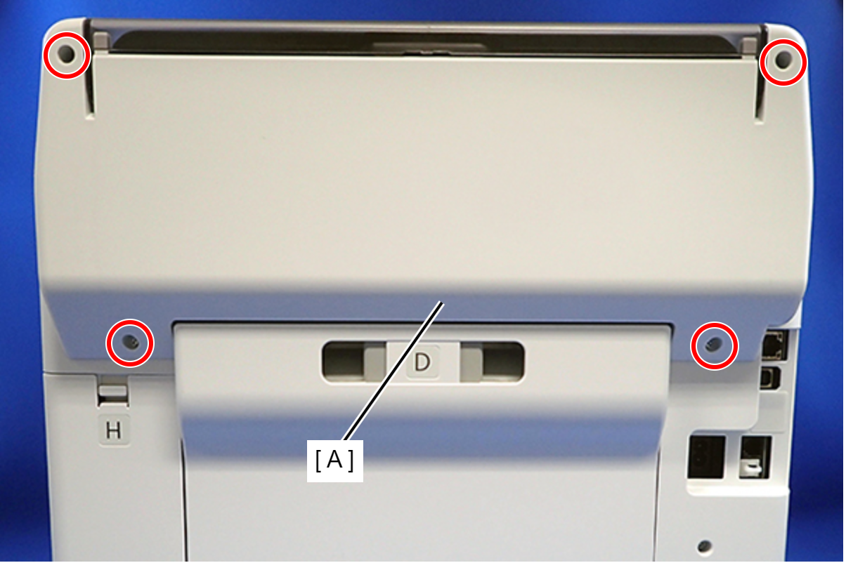
 : C.B.P-TITE-SCREW-3x10-F.ZN-3C
 Assembly / 組み立て
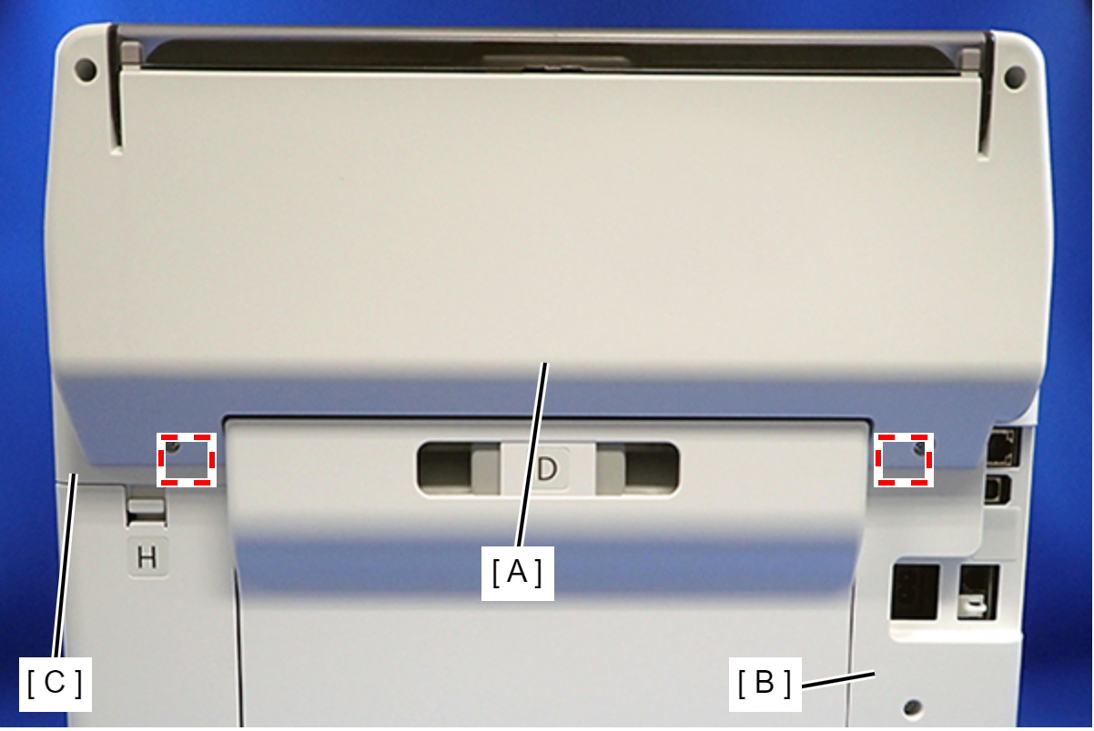
Attach the two dowels of the Rear Cover (Back) (A) to the positioning holes on the Housing Left (B) and Housing Right (C).
- Remove the two screws, then remove the Rear Top Cover (A).
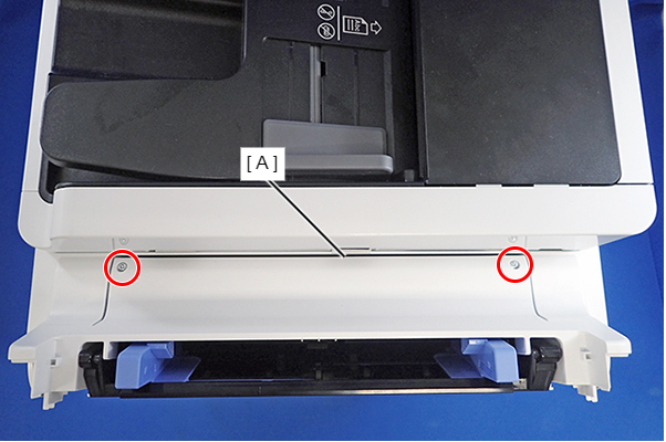
- : C.B.P-TITE-SCREW-3x10-F.ZN-3C
- Open the ADF/SCN Unit and remove the three screws that secure the Housing Left (A).
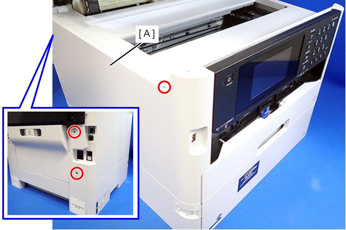
- : C.B.P-TITE-SCREW-3x10-F.ZN-3C
- Lift the Housing Left (A) to release the two hooks on the front side of the Housing Left.
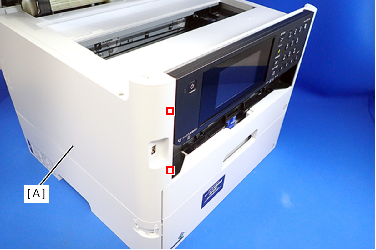
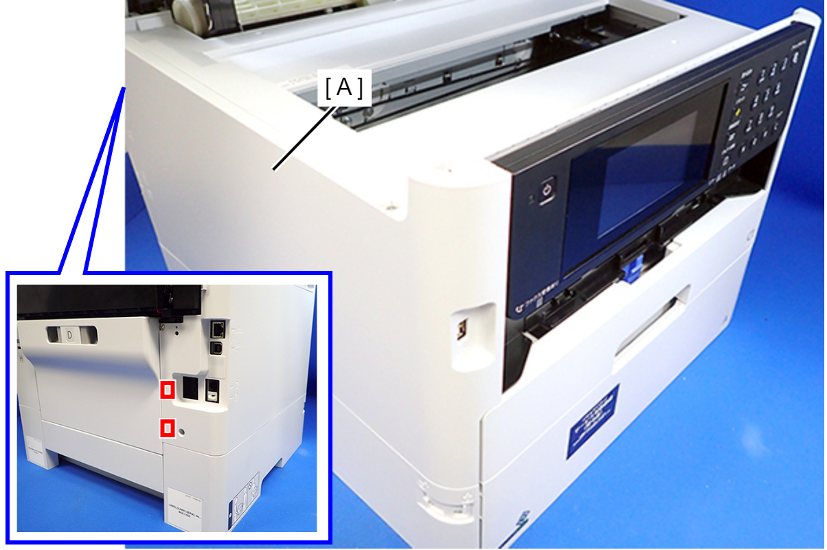
- Disengage two hooks on the rear side of the Housing Left (A), and remove the Housing Left (A).
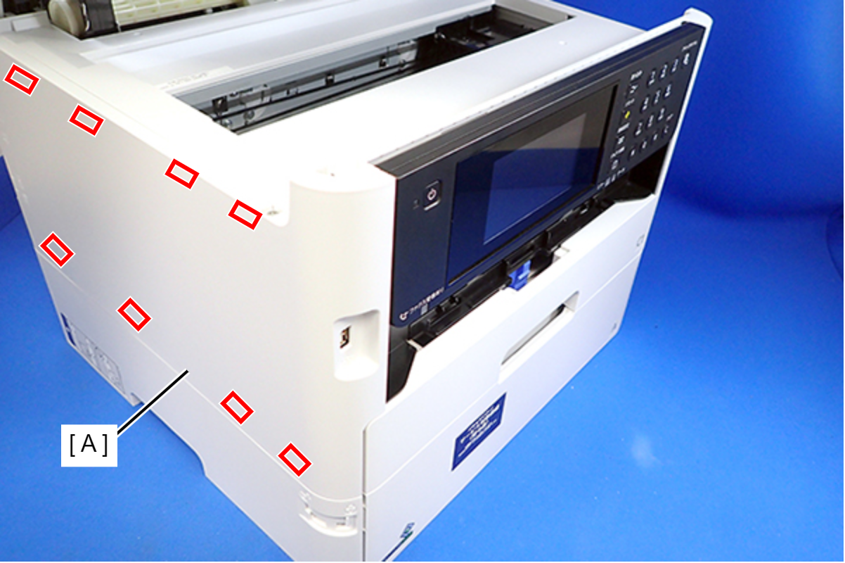
 Assembly / 組み立て
Insert the eight tabs on the Housing Left (A) to the positioning holes of the Housing Upper (B) and the RIPS Unit (C).
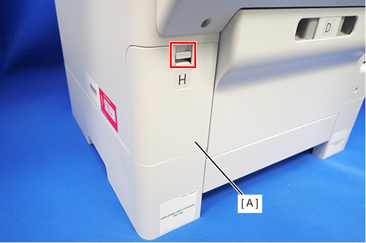
- Disengage the hook, and remove the Maintenance Box Cover (A).
- Open the ADF/SCN Unit and remove the four screws that secure the Housing Right (A).
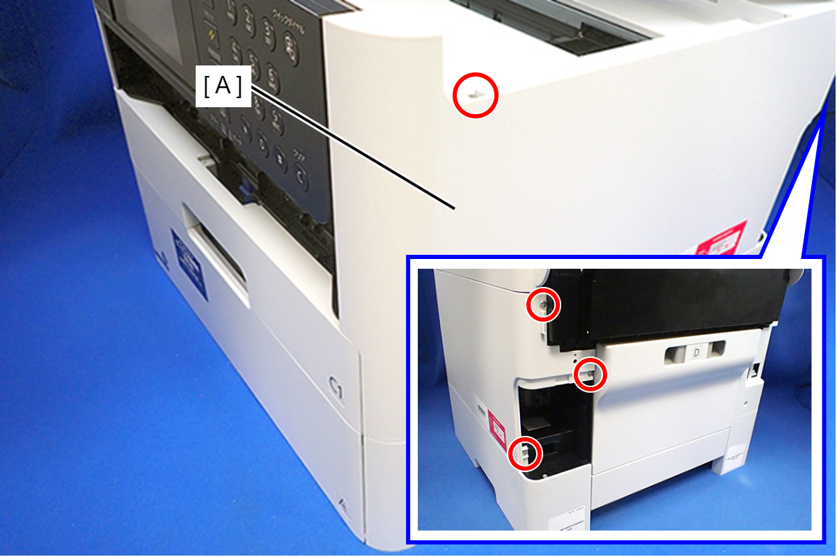
- : C.B.P-TITE-SCREW-3x10-F.ZN-3C
- Lift the Housing Right to release the two hooks on the front side of the Housing Right, then remove the Housing Right.
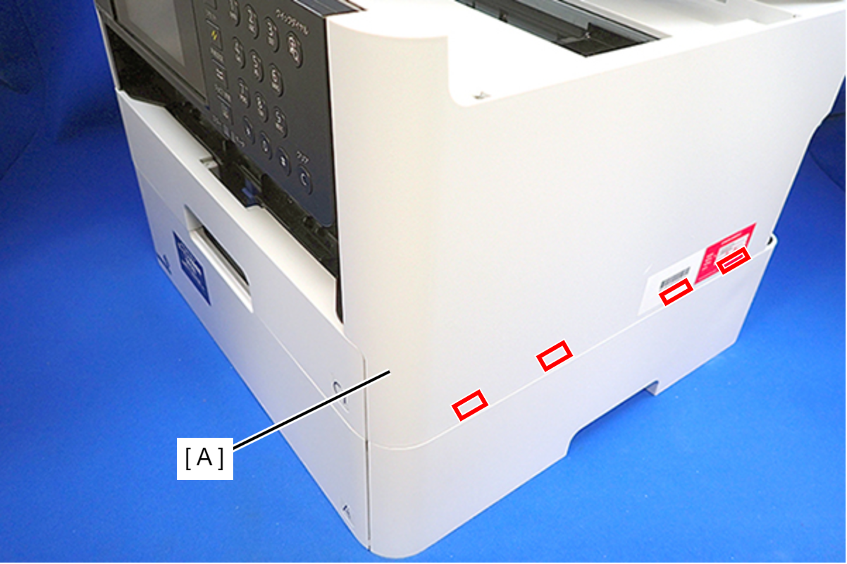
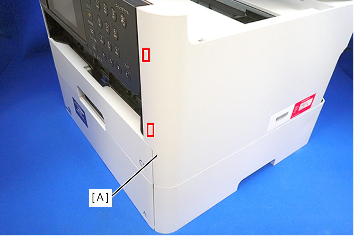 Assembly / 組み立て
Insert the four tabs of the Housing Right (A) to the positioning holes on the Ink Supply Unit.
- Remove the six screws, then remove the Housing Upper (A).
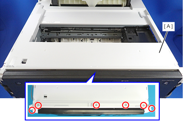
- : C.B.P-TITE-SCREW-3x10-F/ZN-3C
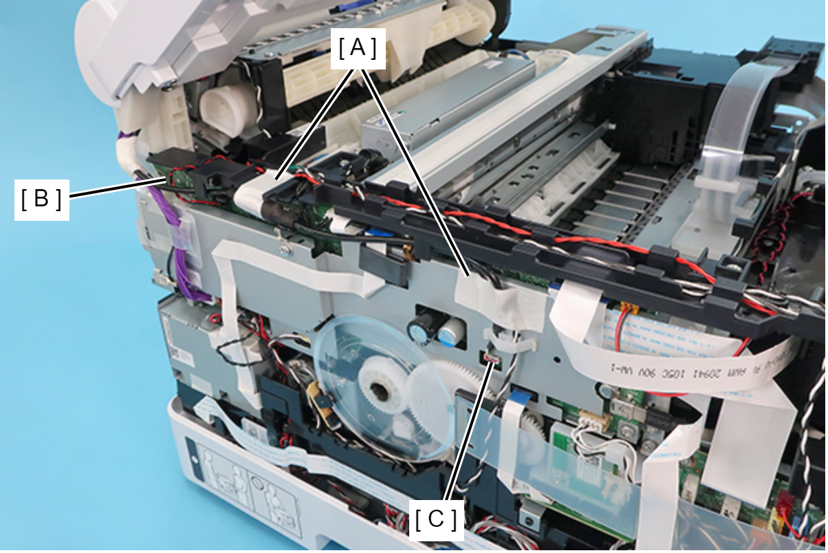
- Remove the two pieces of acetate tape (A), and disconnect the cable (C) from CN100 connector on the Main Board (B).
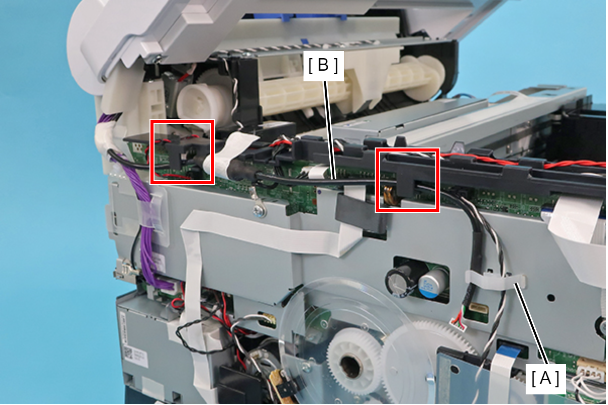
- Release the cable (B) from the two guides and the clamp (A).
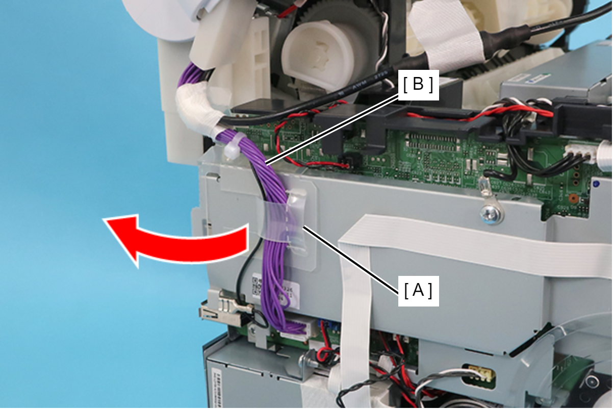
Release the cable (B) from the protective sheet (A) by opening the sheet in the direction of the arrow.
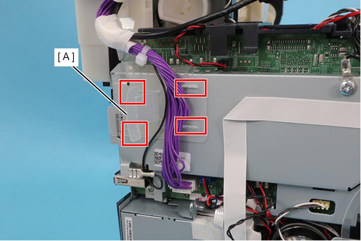
 Assembly / 組み立て
Insert the two tabs of the protective sheet (A) into the two slits respectively.
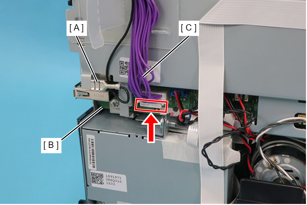
- Disconnect the ground wire (A), and while pushing the connector’s tab upward, disconnect the cable (C) from CN799 connector on the Main Board (B).
- Open the ADF/SCN Unit (A).
 Caution / 注意
- If you remove or attach the ADF/SCN Unit while it is closed, the hinge may be damaged.
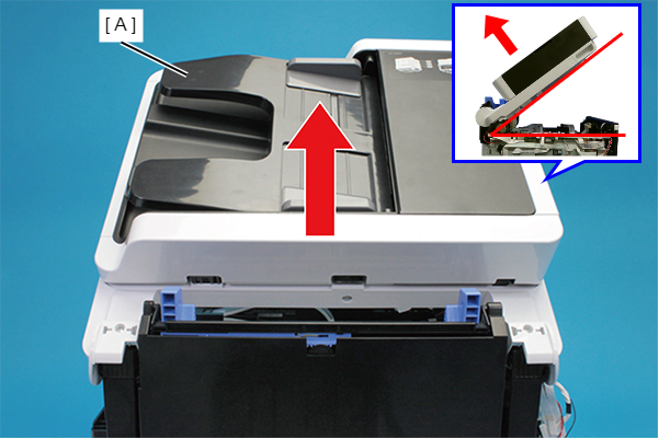
- Remove the two screws and remove the ADF/SCN Unit (A) in the direction of the arrow.
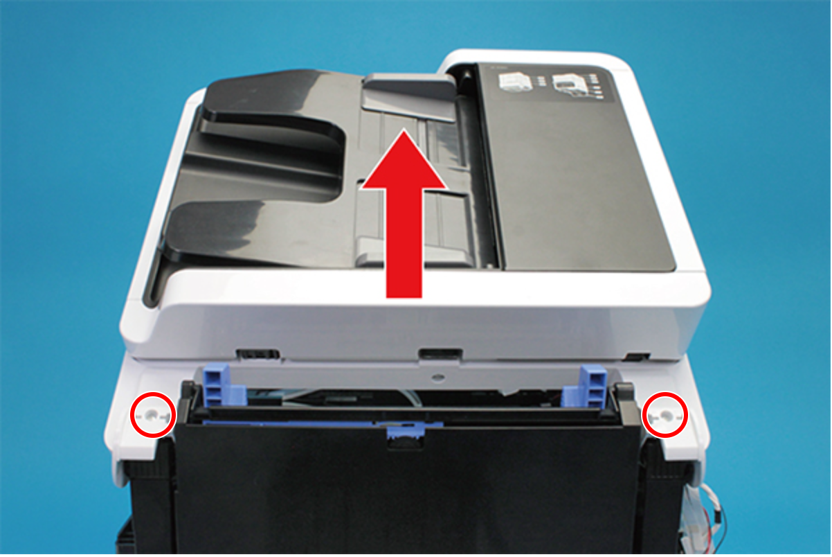
 : C.B.P-TITE-SCREW-3x10-F.ZN-3C
Assembly / 組み立て- Before screwing the ADF/SCN Unit, make sure the hinges are properly attached in place.
If the ADF/SCN Unit is opened when the hinges are NOT secured, the unit may be damaged.
Follow the steps below to unlock the carriage (CR).
 Check Point / チェックポイント
If the carriage is already unlocked and the CR Unit (A) can move freely, as shown below, this step is not necessary.
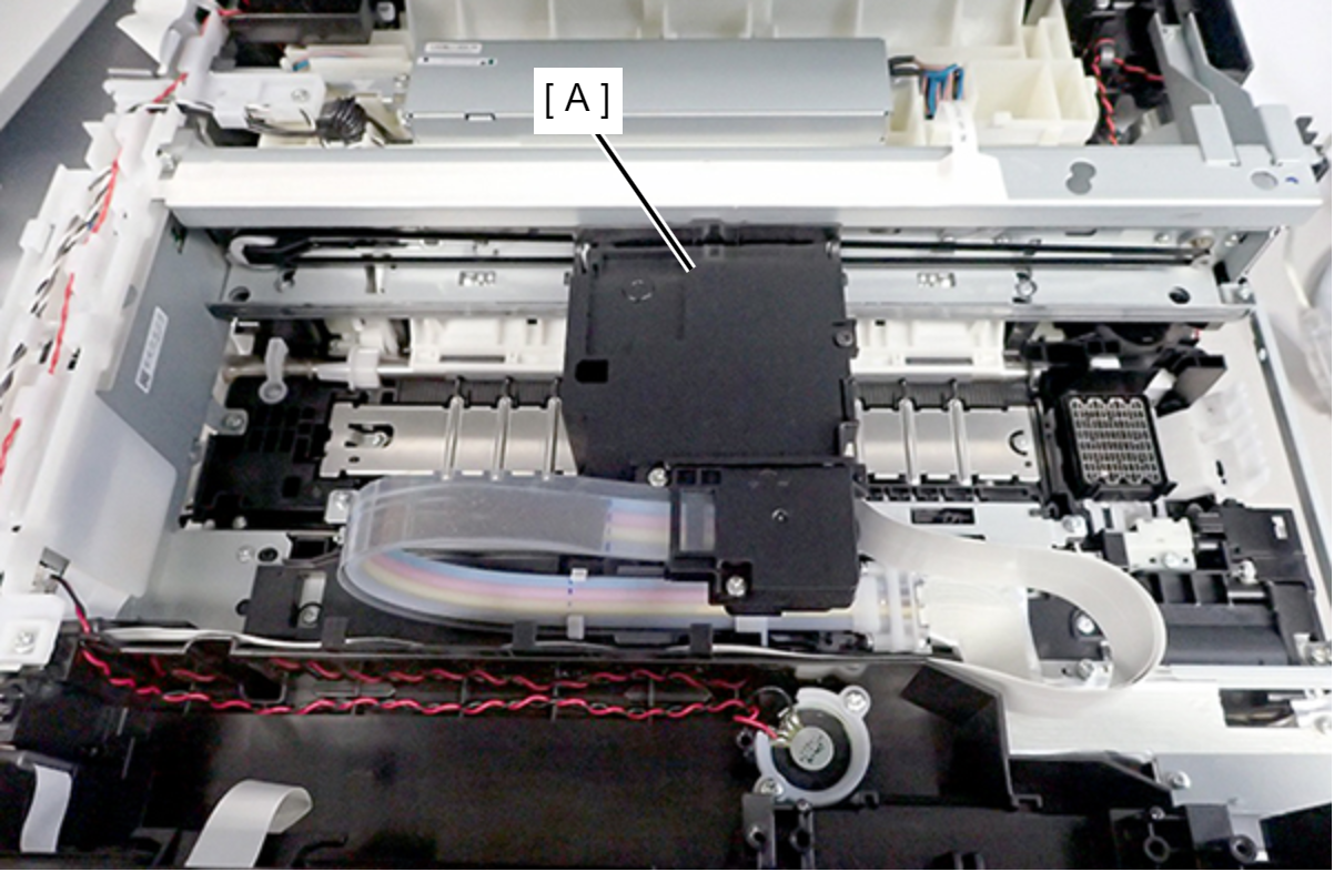
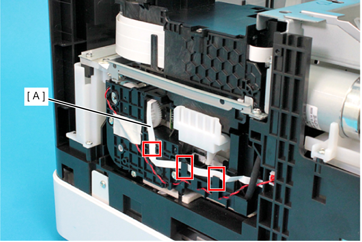
- Release the FFC (A) from the three hooks.
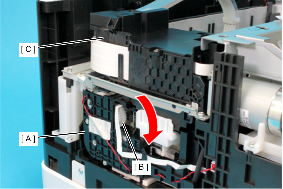
Rotate the gear (B) of the Ink System Unit (A) in the direction of the arrow, and move the CR Unit (C) to the left side.
 Caution / 注意
When rotating the gear of the Ink System Unit, take extra care not to damage or disconnect the FFC by touching it.
- Release the FFC (A) from the three hooks.
- Remove the two screws, and then remove the Head Upper Cover (A).
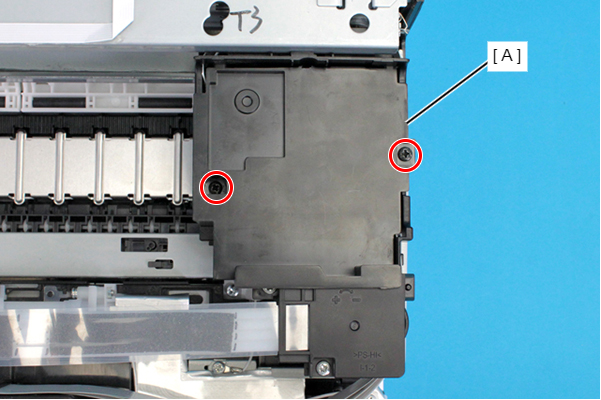
- : C.B.P-TITE-SCREW-3x10-F.ZB-3C
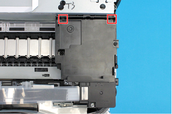
Assembly / 組み立てAttach the two tabs on the Head Upper Cover to the positioning holes of the CR Unit.
- Remove the two screws, and remove the Ink Tube Joint Cover (A).
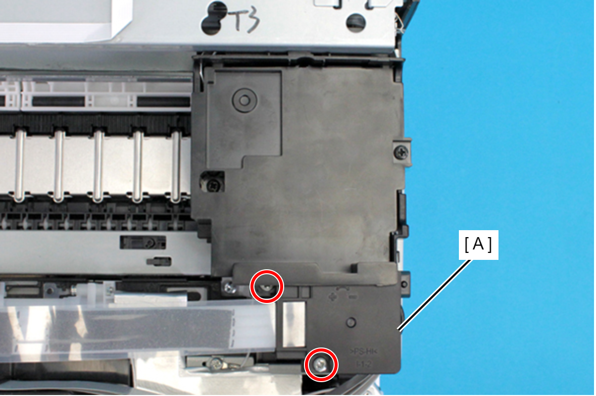
- : C.B.P-TITE-SCREW-3x10-F.ZN-3C
- Remove the film (A) from the hook on the Ink Tube Joint Cover.
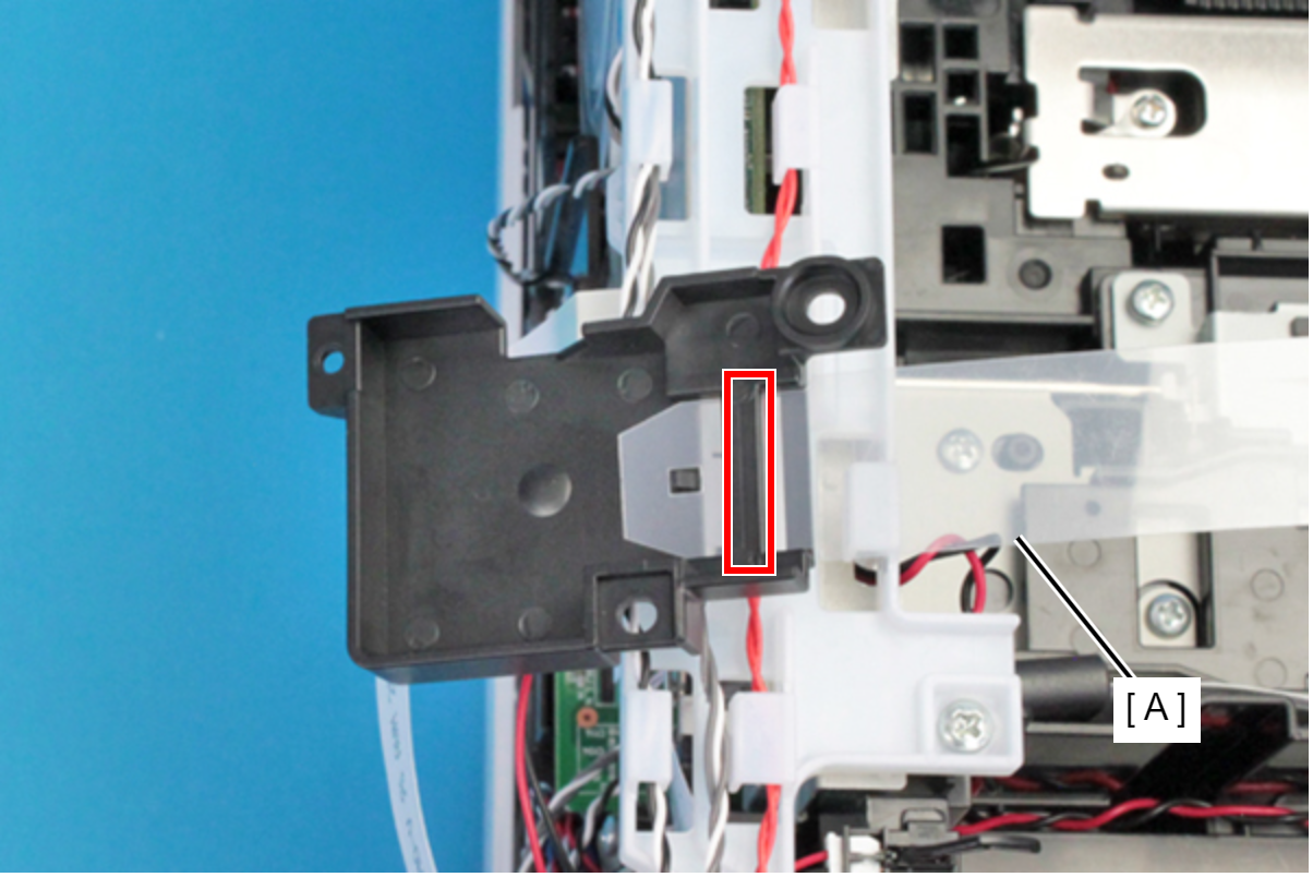
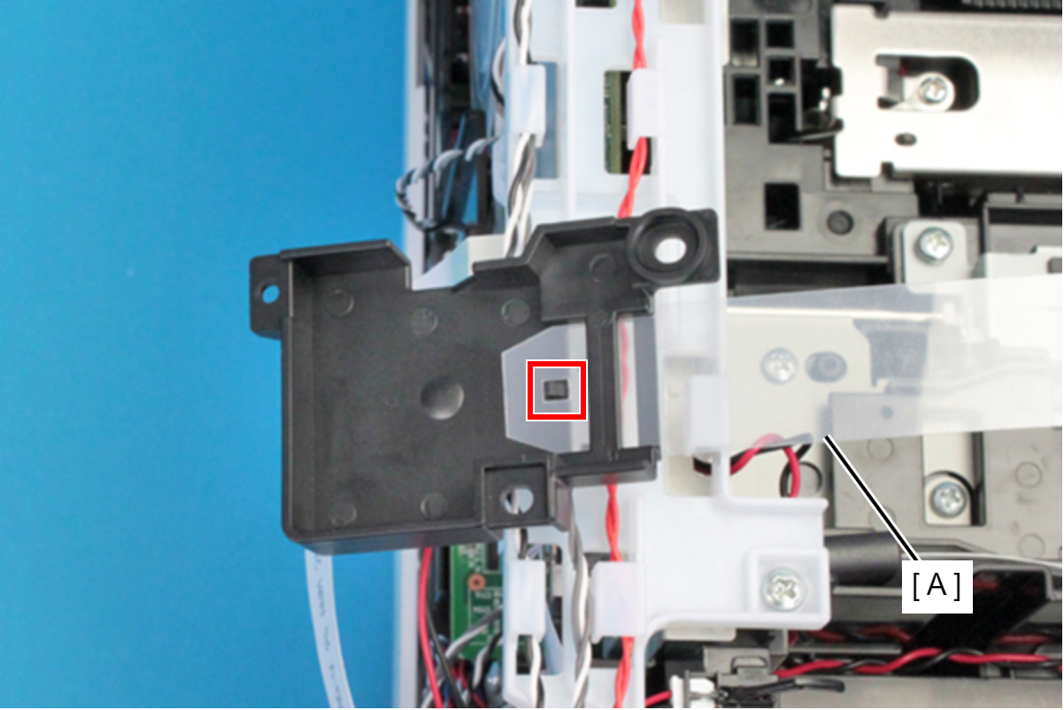 Assembly / 組み立て
Set the film (A) under the rib of the Ink Tube Joint Cover.
- Remove the two screws, and remove the Ink Tube Joint Cover (A).
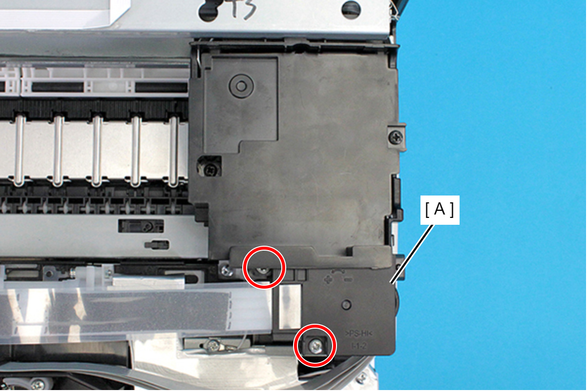
- : C.B.P-TITE-SCREW-3x10-F.ZN-3C
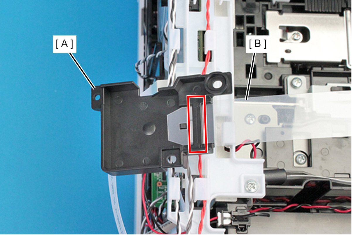
- Remove the film (A) from the hook and remove the Ink Tube Joint Cover (B).
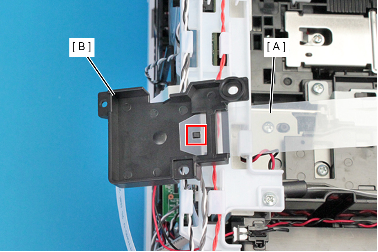 Assembly / 組み立て
Set the film (B) under the rib of the Ink Tube Joint Cover (A).
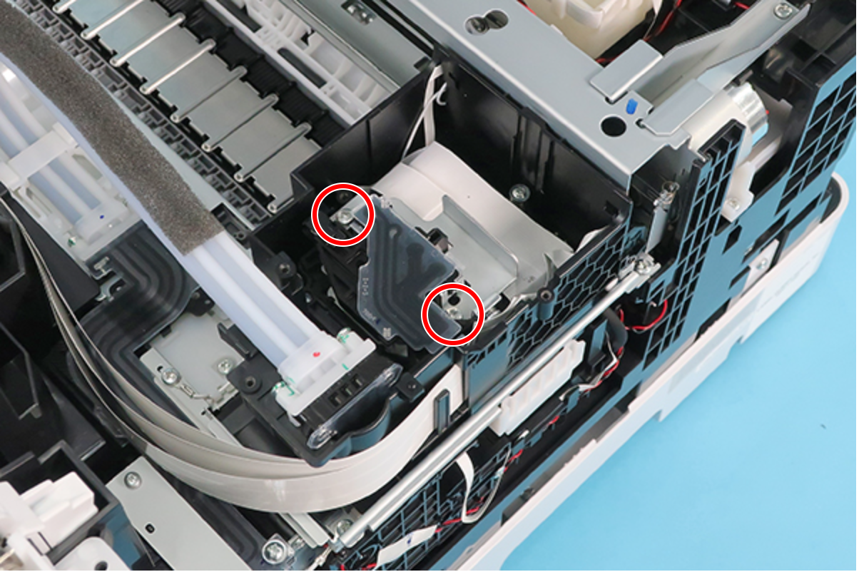
- Remove the two Bind Screw3 x 12 (w/washer).
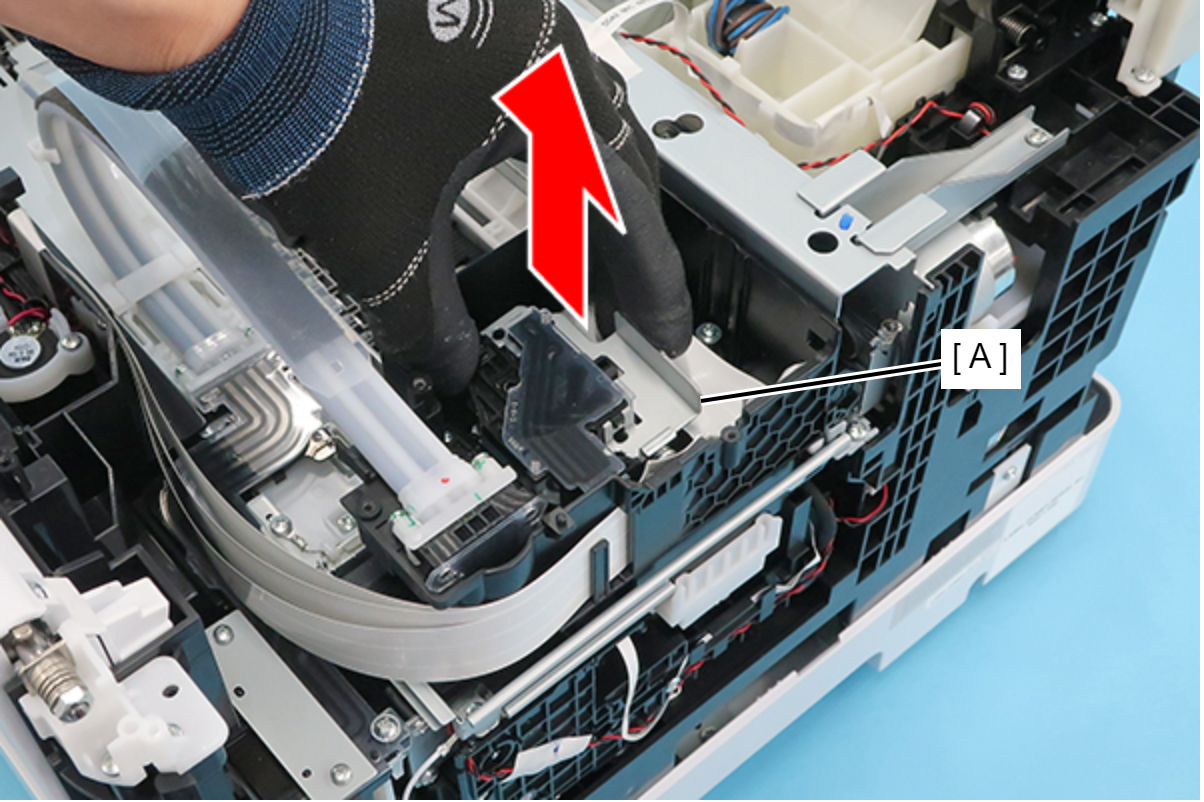
- Remove the Ink Supply Tube (A) by pulling it straight in the direction of the arrow.
 Check Point / チェックポイント
Pull the end (A) of the Ink Supply Tube straight up while keeping it horizontal.
To keep it horizontal, it is recommended to work by grasping the end of the Ink Supply Tube with both hands.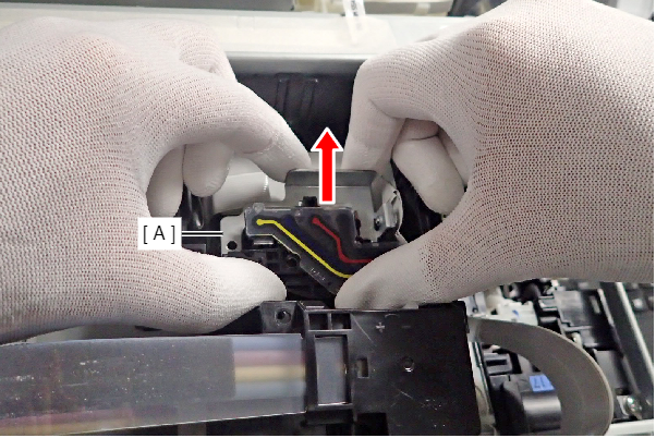 Caution / 注意
Ink may spill from the Ink Supply Tube. Prepare waste cloths or similar in advance.
- Never pull out the Ink Supply Tube at an angle, as ink leakage will occur if the tube is pulled out at an angle.
The following illustrations show images of removing the Ink Supply Tube as seen from the front of the printer.- OK
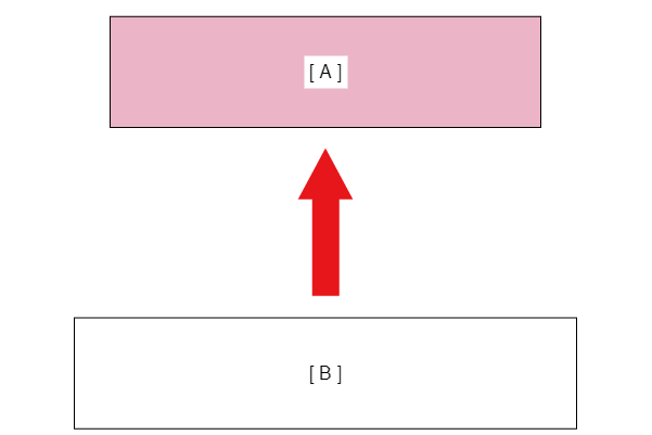
- A: Ink Supply Tube
B: Printhead
- A: Ink Supply Tube
- NG
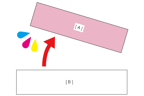
- A: Ink Supply Tube
B: Printhead
- A: Ink Supply Tube
- OK
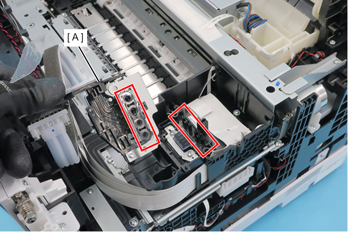
Assembly / 組み立てWhen attaching the ink Supply Tube (A), insert the four nozzles into each of the four connection holes, and insert them all the way in.
Remove the three Head Screw Assy.
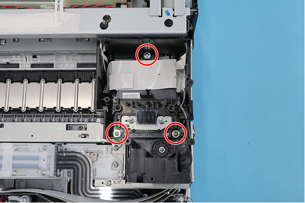 Assembly / 組み立て
Tighten the screws in order given below.
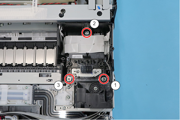
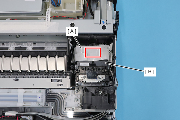
- Remove the double-sided tape from the Head FFC Assy (A), and remove the Printhead (B).
 Caution / 注意
Do not touch the nozzle surface of the Printhead.
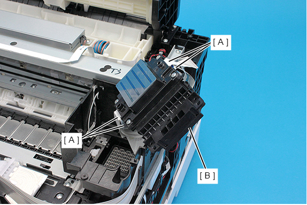
- Disconnect the Head FFC Assy from the four connectors and remove the Printhead (B).
 Assembly / 組み立て
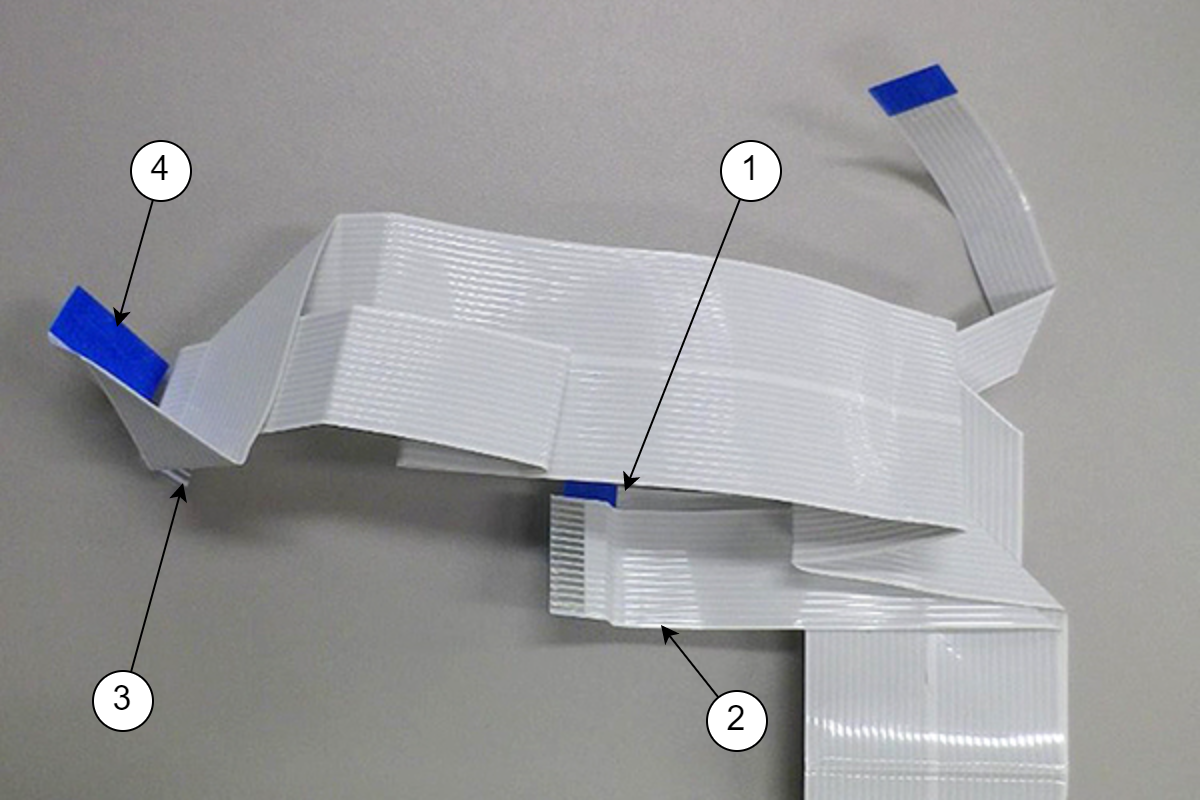
The correspondence between the four printhead connectors and the four Head FFC Assy FFCs is as below.
- Head FFC Assy
- Printhead
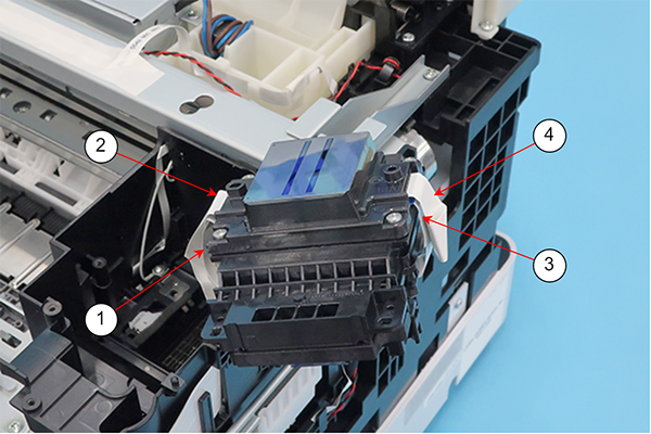
- Head FFC Assy
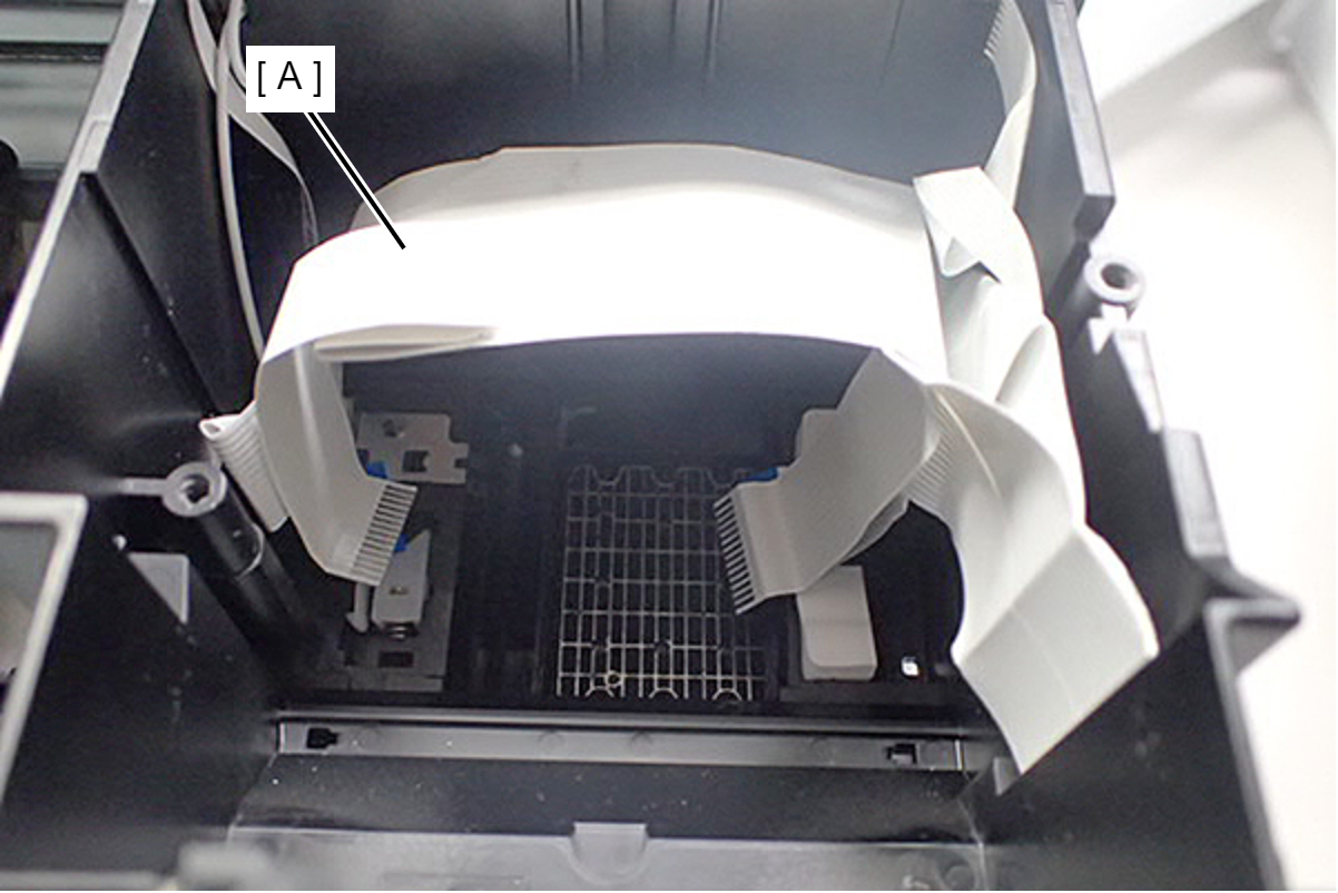
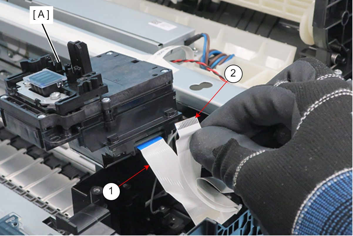
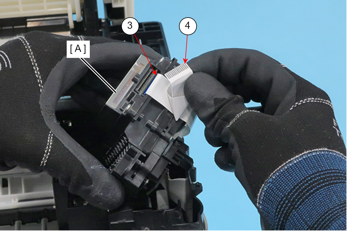
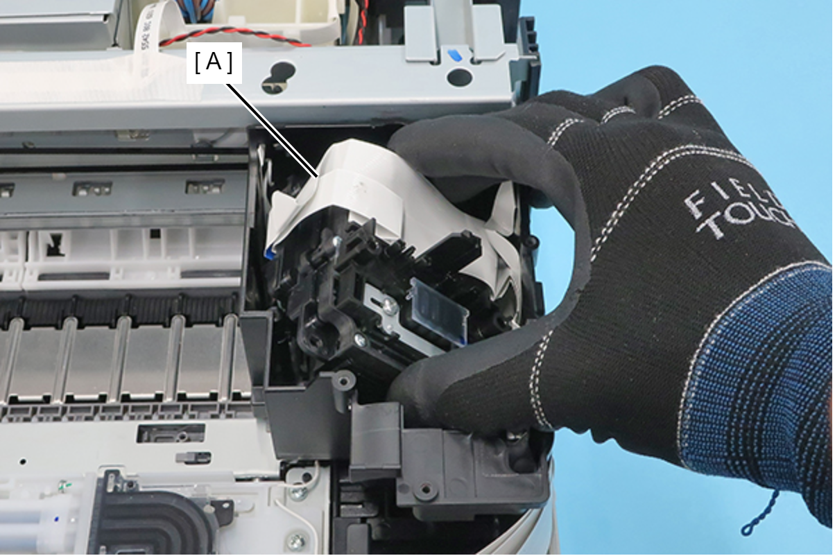
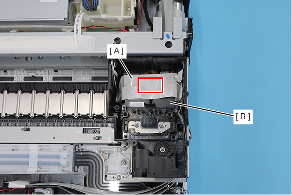
- Install the Printhead in accordance with the following procedure.
- Ensure the Head FFC Assy (A) is as below.
- Connect FFC (1) and FFC (2) to the two connectors on the right side of the Printhead (A).
- Connect FFC (3) and FFC (4) to the two connectors on the left side of the Printhead (A).
- Install the Printhead (A) from the right side of the Printhead (A).
- Using double-sided tape, affix the Head FFC Assy (A) to the Printhead (B).
| Adjustment / 調整 |
After replacing this part, you need to run the menu from the service support mode. (If you ran the Before-replacement menu before replacing the part, it will start automatically when you turn the power on.) |