
Panel Assy (EP-C800 Series)
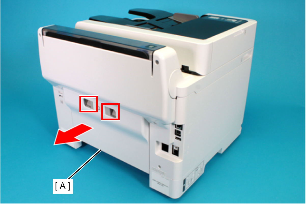
- Remove the Rear Unit (A) in the direction of the arrow while pressing the buttons inward.
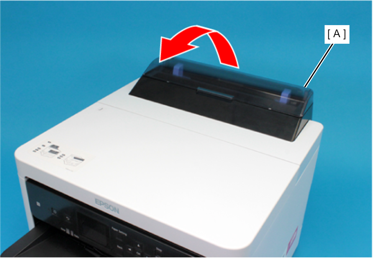
- Open the ASF Cover (A) and remove the two screws securing the Rear Housing Assy (B).
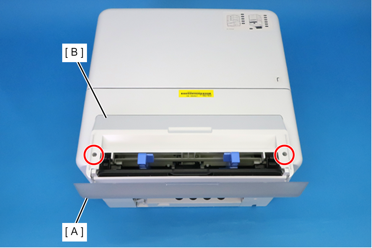
 : C.B.P-TITE-SCREW-3x10-F.ZB-3C
- Remove the four screws that secure the Rear Back Cover (A).
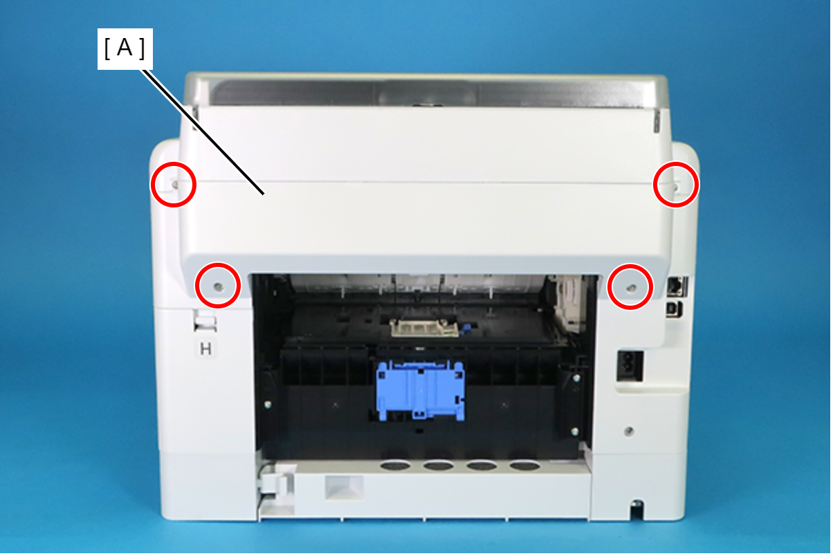
 : C.B.P-TITE-SCREW-3x10-F.ZN-3C
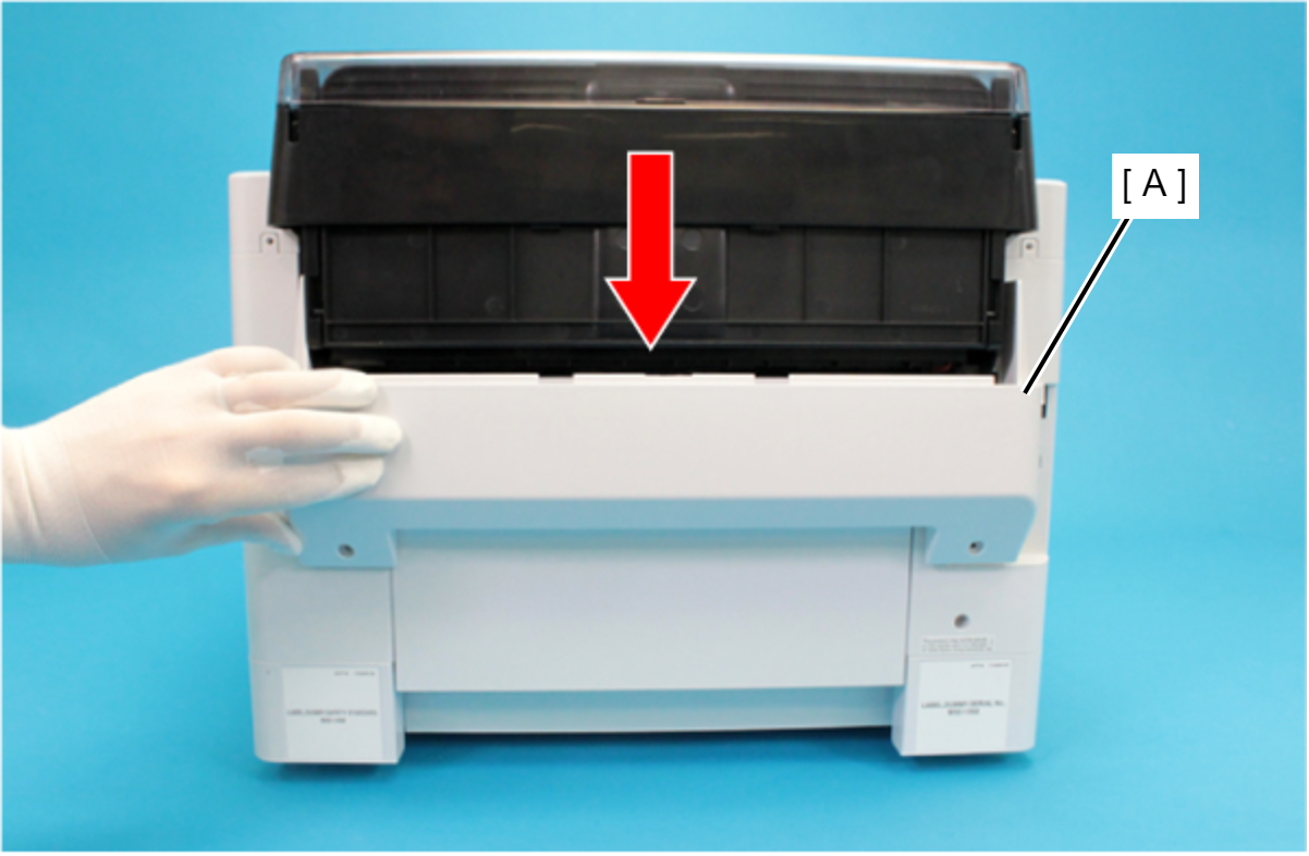
- Remove the Rear Back Cover (A) downward.
 Assembly / 組み立て
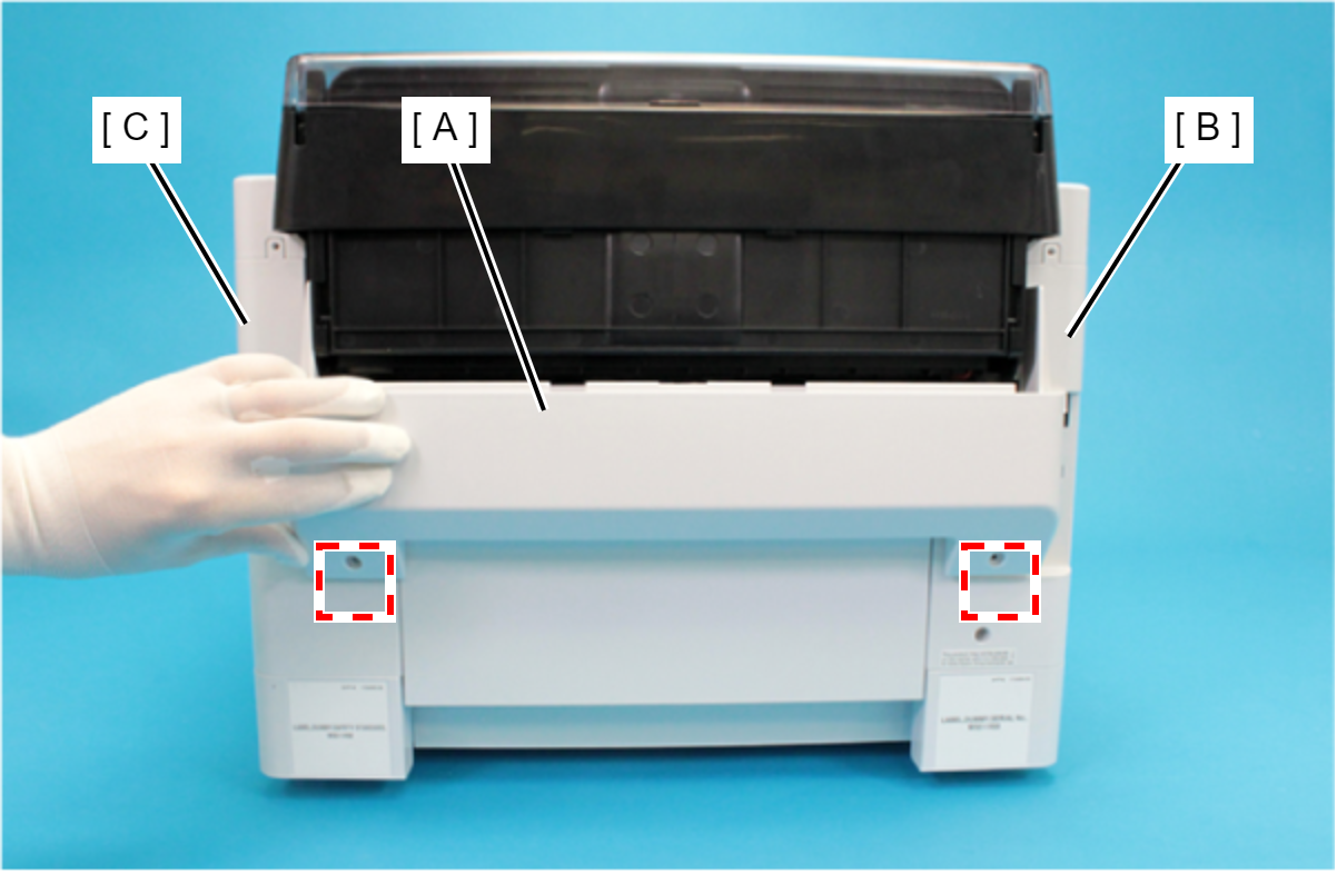
Attach the two dowels of the Rear Back Cover (A) to the positioning holes on the Housing Left (B) and the Housing Right (C).
- Remove the Rear Upper Cover Assy (A) in the direction of the arrow.
 Assembly / 組み立て
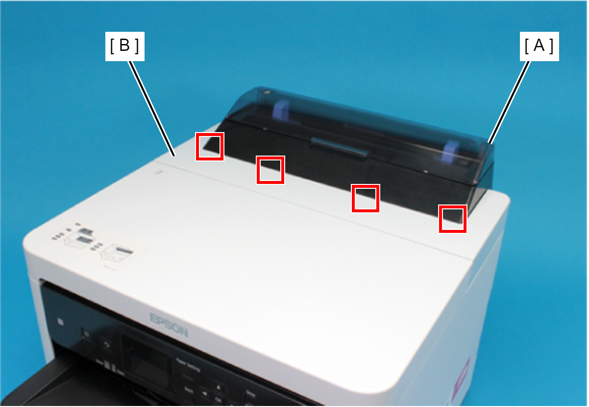
Insert the four tabs of the Rear Upper Cover Assy (A) to the positioning holes of the Housing ASF (B).
- Remove the two screws securing the Housing ASF (A).
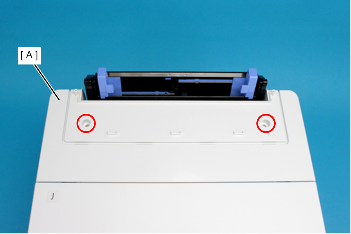
- : C.B.P-TITE-SCREW-3x10-F.ZN-3C
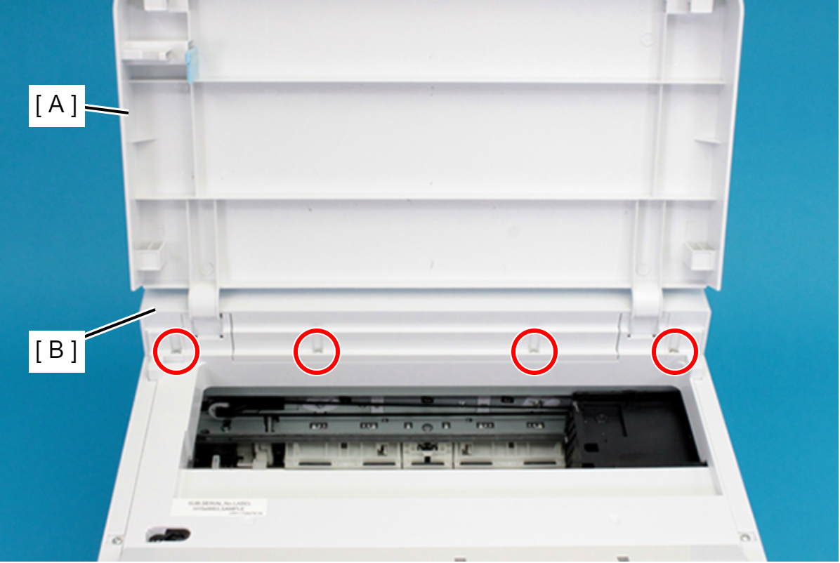
- Open the Printer Cover (A) and remove the four screws, and then remove the Housing ASF (B).
- : C.B.P-TITE-SCREW-3x10-F.ZN-3C
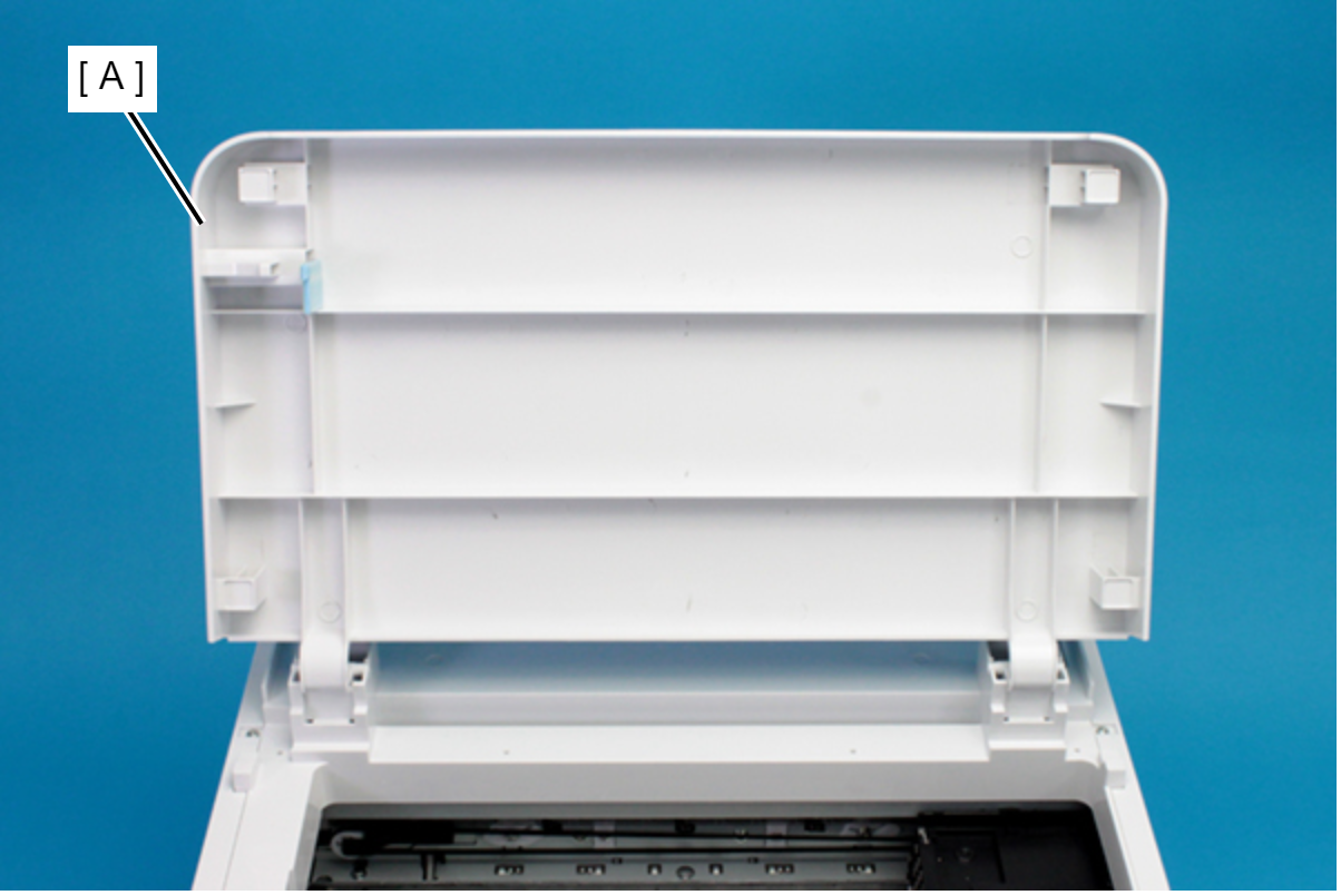
- Remove the Printer Cover (A) upward.
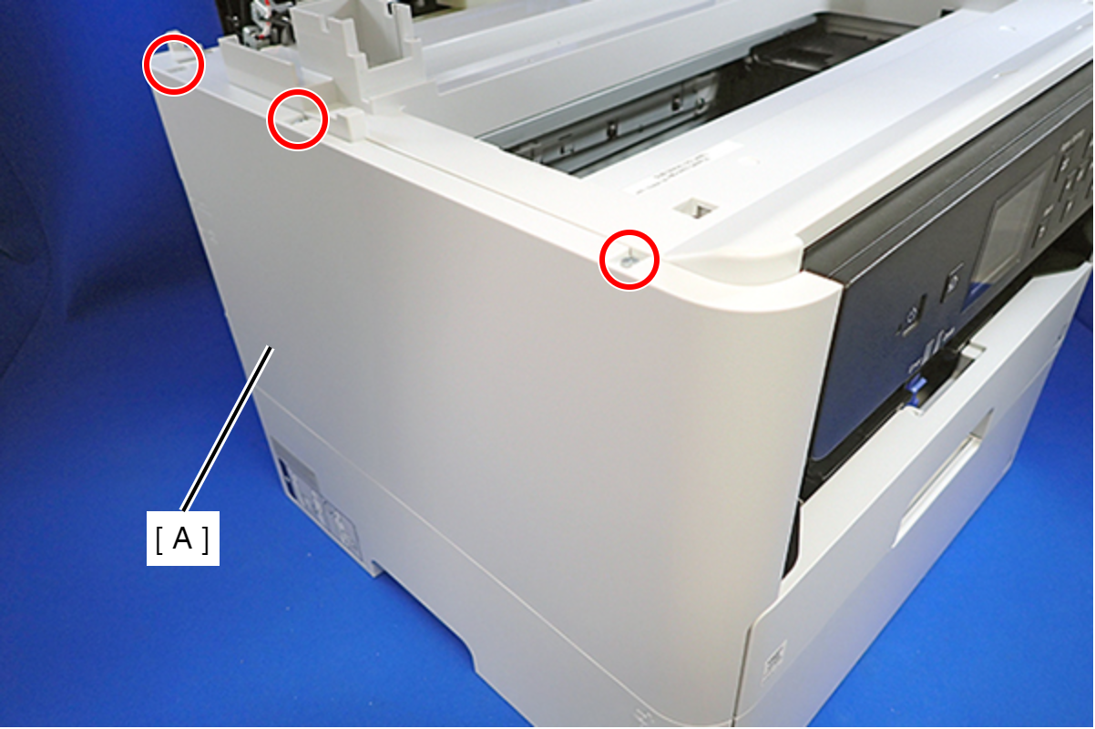
- Remove the three screws that secure the Housing Left (A).
- : C.B.P-TITE-SCREW-3x10-F.ZN-3C
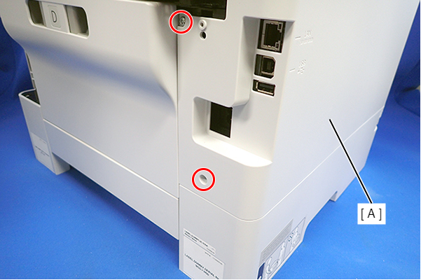
- Remove the two screws that secure the Housing Left (A).
- : C.B.P-TITE-SCREW-3x10-F.ZN-3C
- Lift the Housing Left (A) to release the two hooks each on the front side and rear side of the Housing Left (A), and then remove the Housing Left (A).
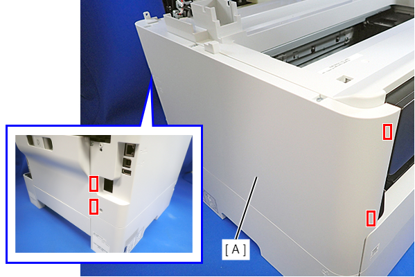
Assembly / 組み立てInsert the four tabs on the Housing Left (A) to the positioning holes of the Ink Supply Unit (B).
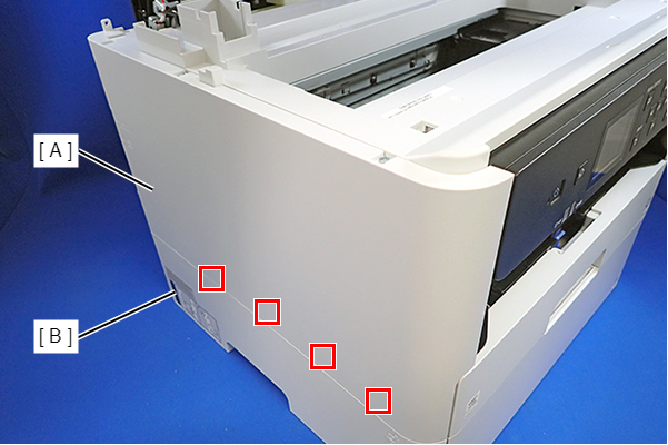
- Disengage the hook, and remove the Maintenance Box Cover (A).
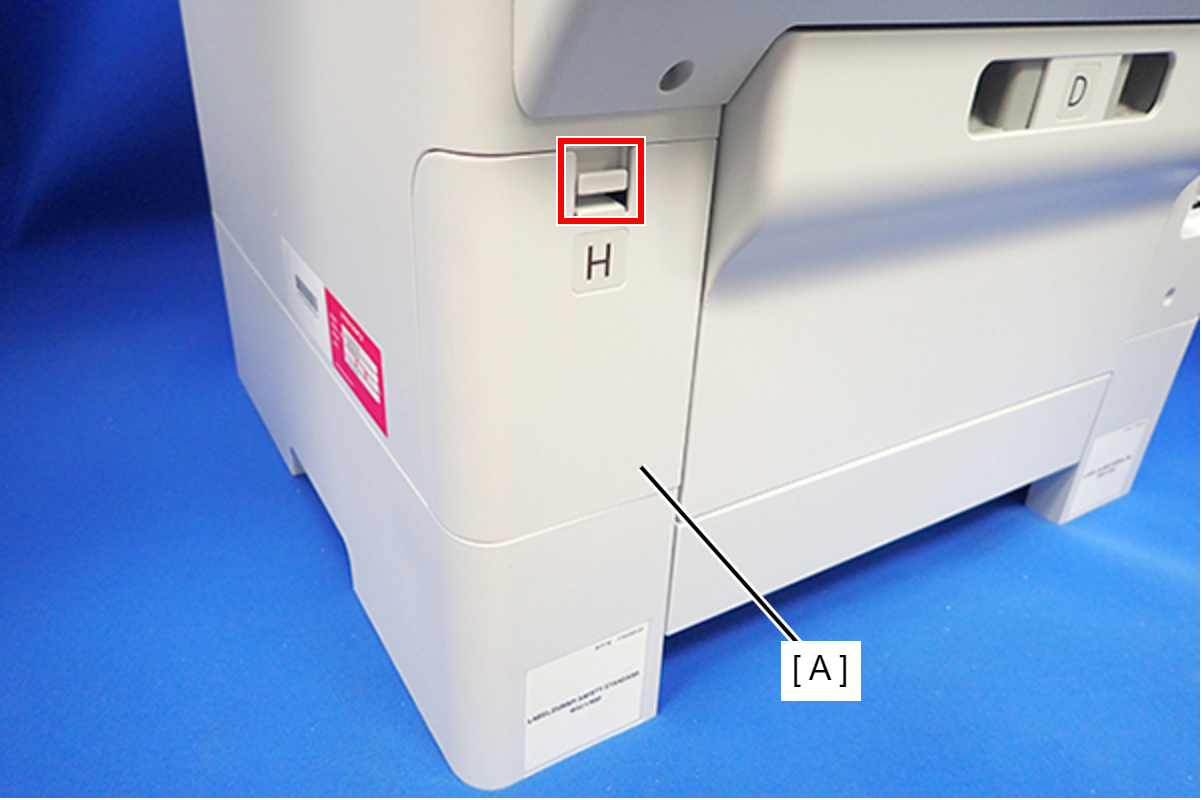
- Remove the three screws that secure the Housing Right (A).
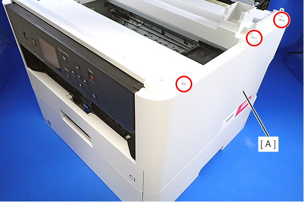
 : C.B.P-TITE-SCREW-3x10-F.ZN-3C
- Remove the two screws that secure the Housing Right (A).
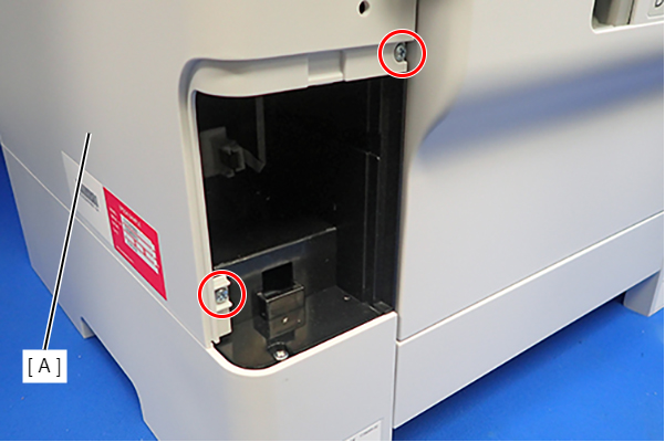
- : C.B.P-TITE-SCREW-3x10-F.ZN-3C
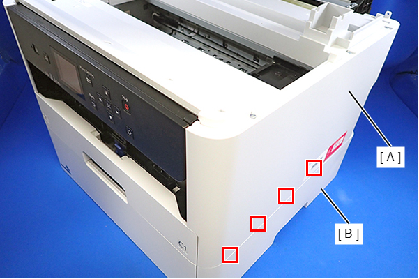
- Lift the Housing Right (A) to release the two hooks on the front side of the Housing Right (A), then remove the Housing Right (A).

Assembly / 組み立てInsert the four tabs of the Housing Right (A) to the positioning holes on the Ink Supply Unit (B).
- Remove the seven screws and remove the Housing Top (A).
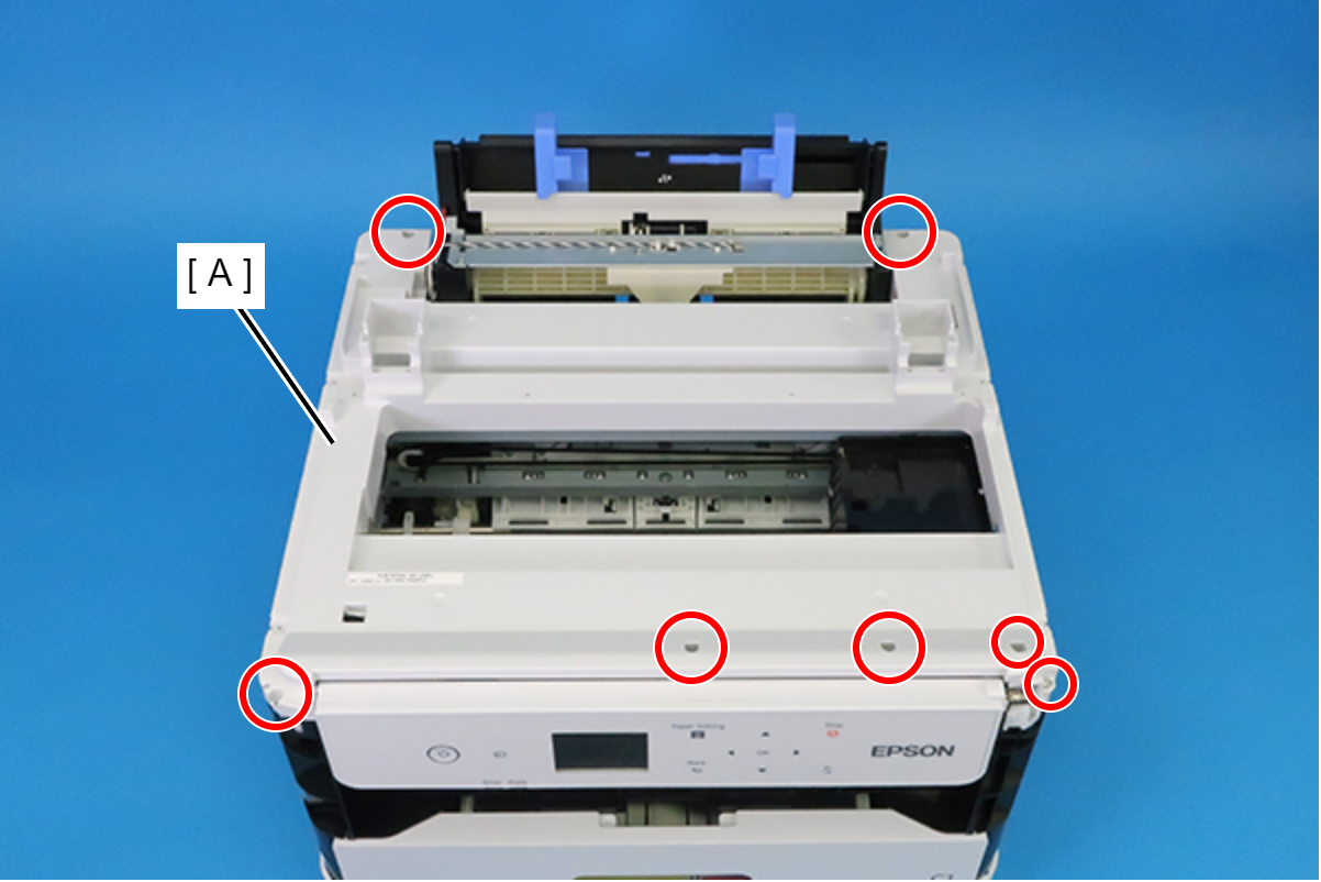
- : C.B.P-TITE-SCREW-3x10-F.ZN-3C
- Remove the two screws securing the Cable Guide (A).
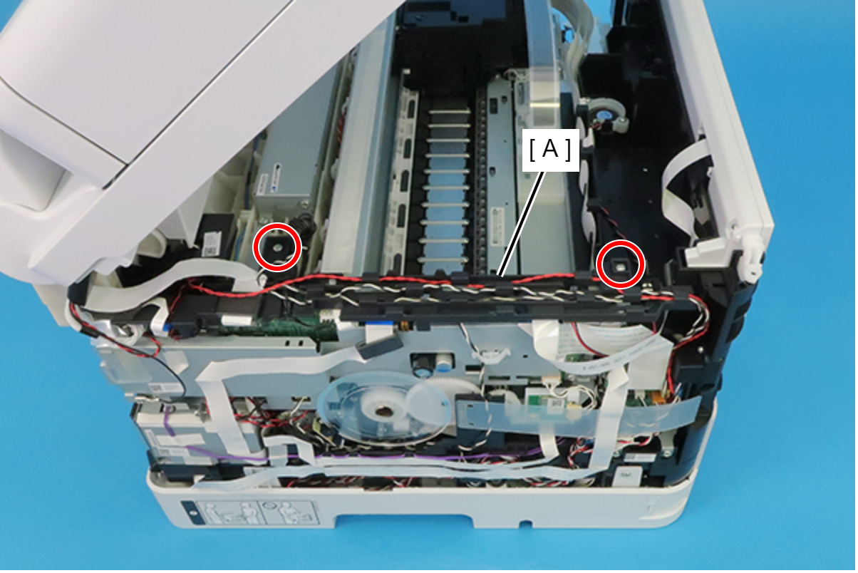
- : C.B.P-TITE-SCREW-3x10-F.ZN-3C
 Check Point / チェックポイント
When removing the screws, if the screwdriver interferes with the ADF/SCN Unit, use a stubby screwdriver.
- Peel off the CRCM FFC (B) from the CRCM FFC Sheet (A).
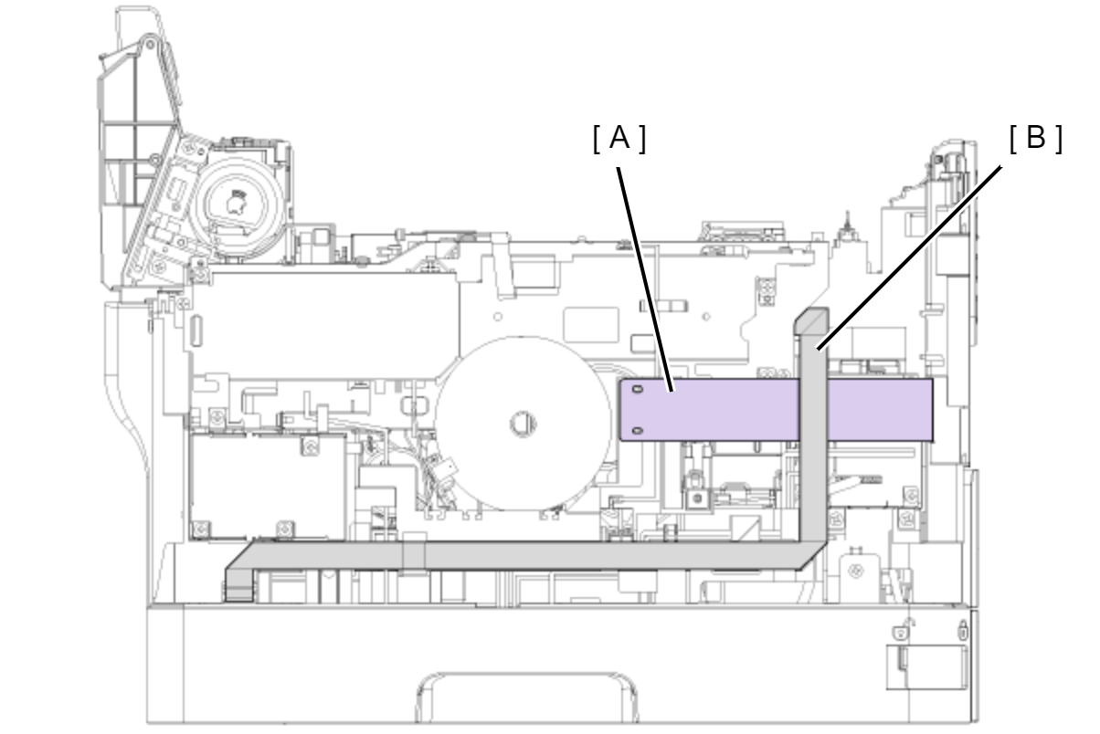
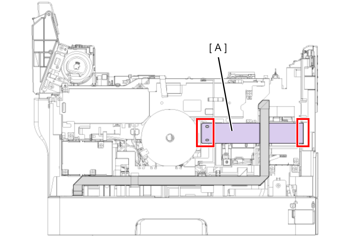
- Peel off the double-sided tape at two locations and then remove the CRCM FFC Sheet (A).
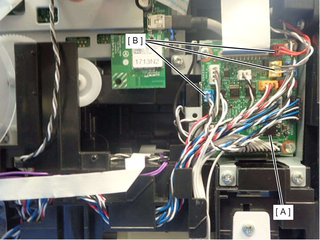
- Disconnect the cables (B) from the connector (CN20, CN51, CN56) of the Relay Board (A).
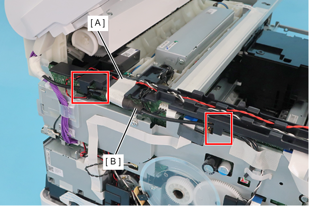
- Remove the acetate tape (A), and release the cable (B) from the two guides.
- Disconnect the two cables (B) from the connectors (CN74, CN80) of the Main Board (A).
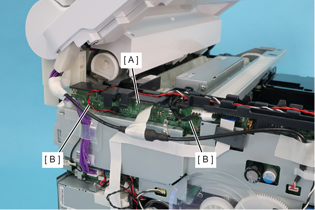
- Remove the two screws, and release the ground wire (A) from the slit to remove it.
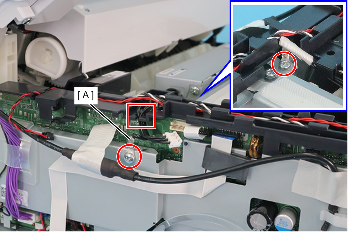
- : C.B.S-TITE-SCREW-3x6-F.ZN-3C
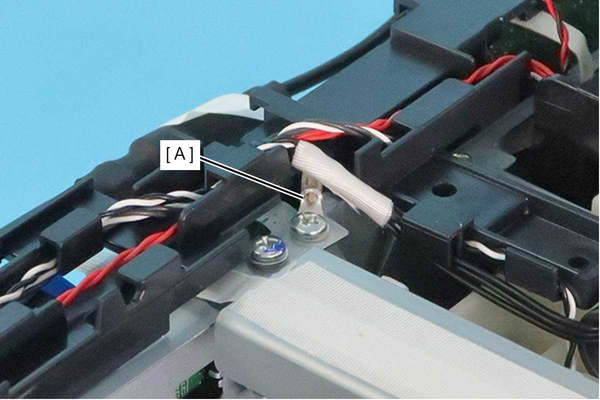
Assembly / 組み立てAttach the ground wire with the terminal (A) oriented as shown below.
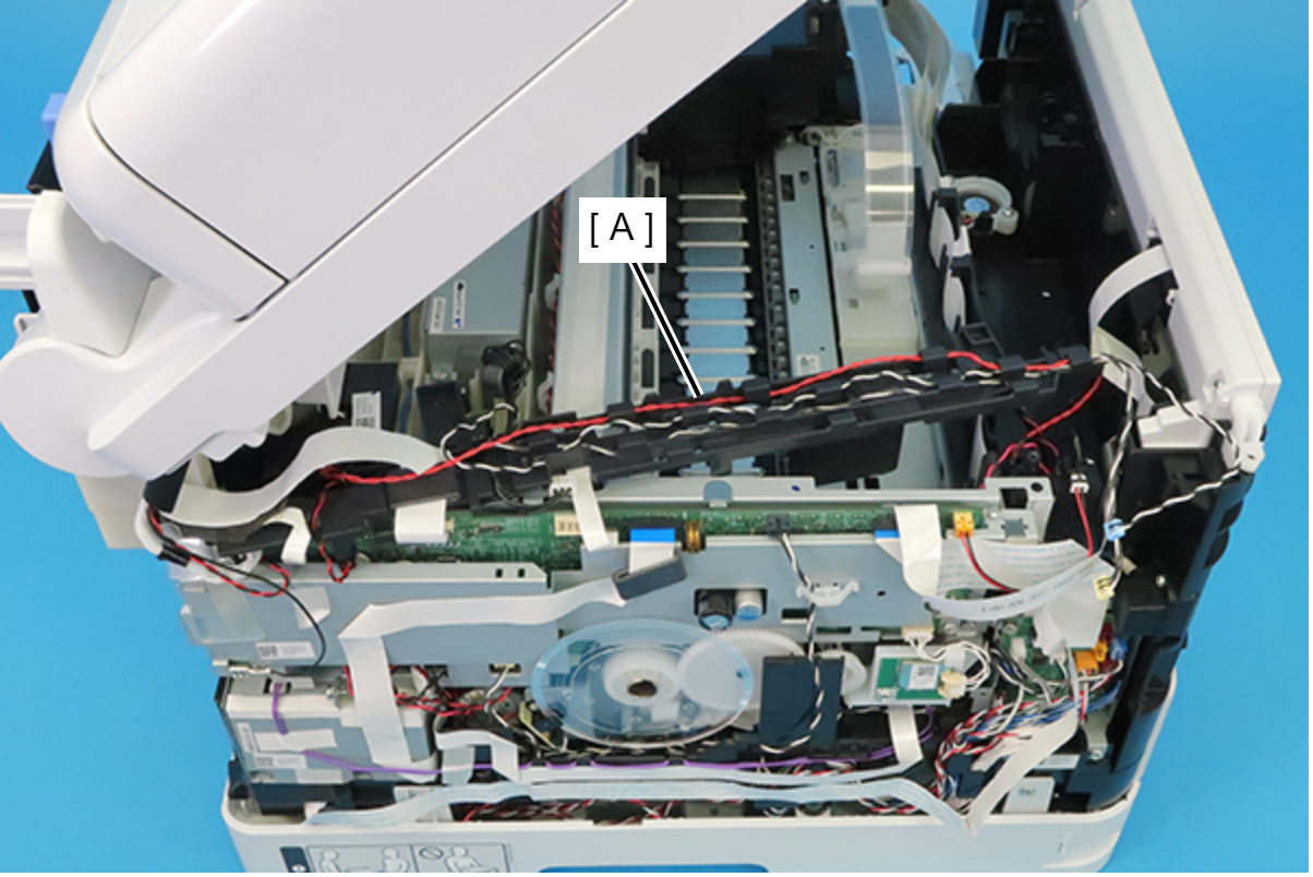
- Move the Cable Guide as shown below.
- Disconnect the FFC (C) from the connector (CN42) (B) on the Main Board Assy (A).
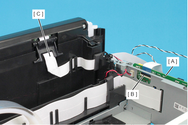 Check Point / チェックポイント
When disconnecting the FFC (A), make sure to unlock the connector lock (B) beforehand.
- Close
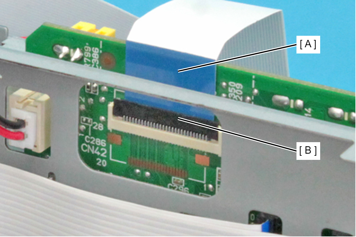
- Open
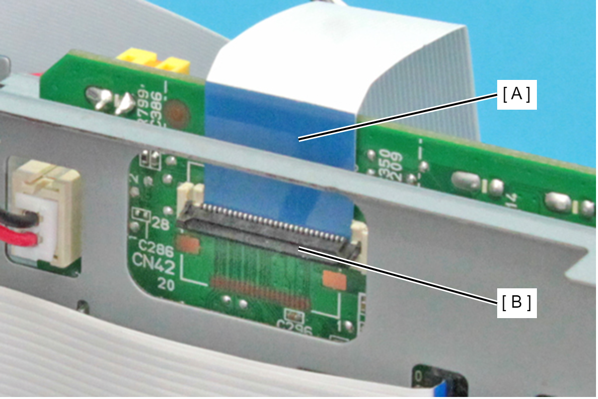
- Close
- Peel off the double-sided tape of the FFC (B) from the Frame Base (A).
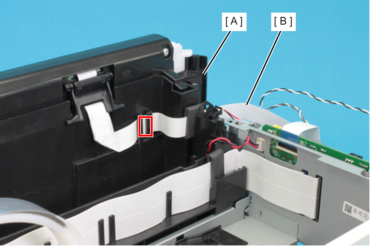
- Release the FFC (B) from two tabs on the Frame Base (A).
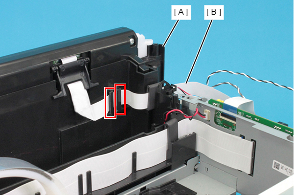 Assembly / 組み立て
Set the ferrite core (B) of the FFC (A) in the point shown below.
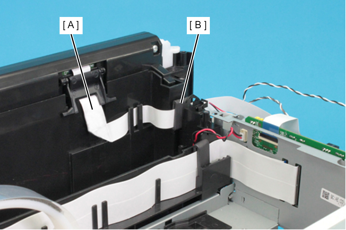
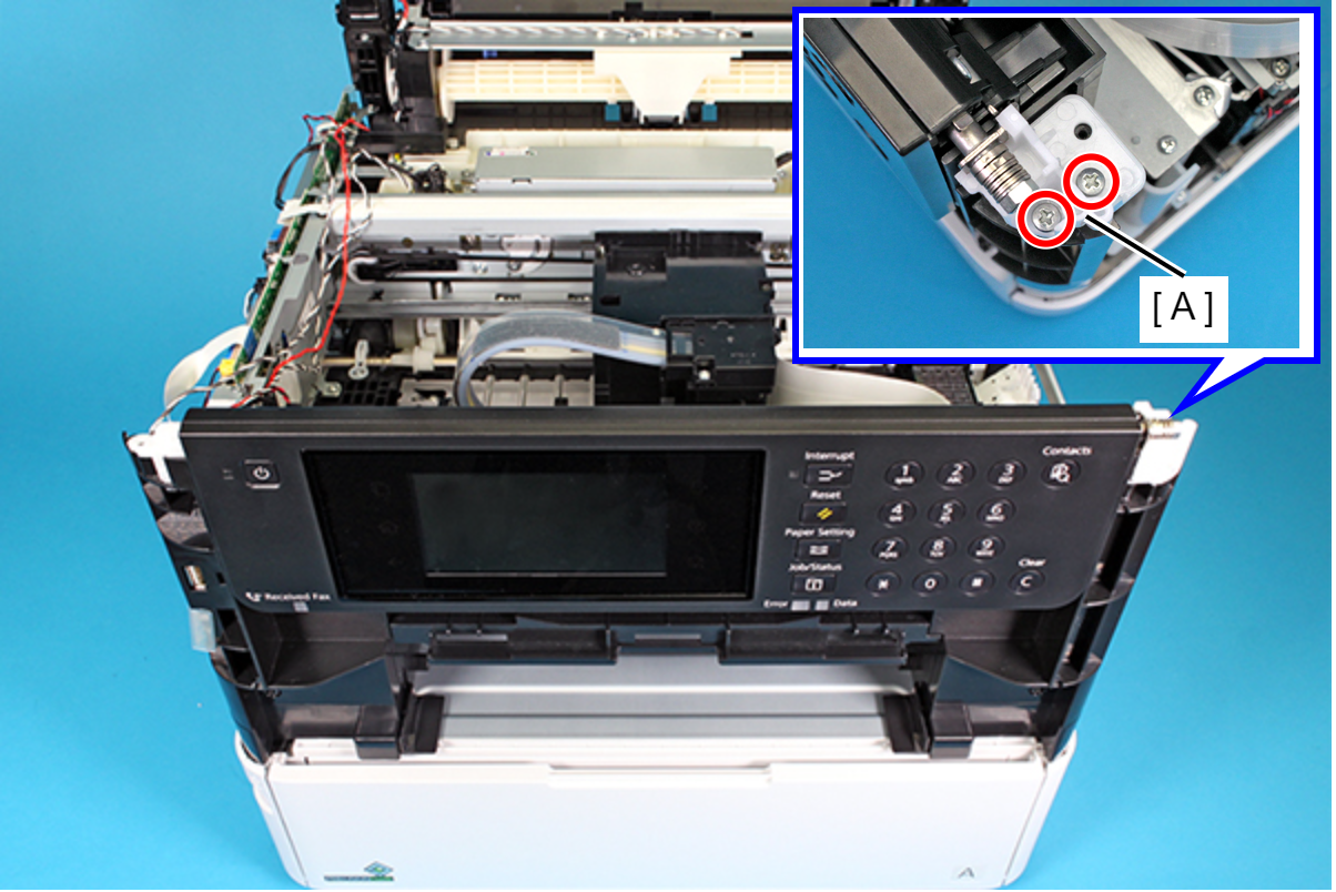
- Remove the two screws, then remove the Right Panel Holder (A).
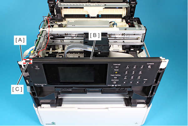
- Release the shaft (C) of the Panel Assy (B) from bearing (A), then remove the Panel Assy (B).
-
- : C.B.P-TITE-SCREW-3x10-F.ZN-3C