60115 Head Angular Adj. (H/W)
Overview
Use software to correct the vertical/horizontal tilt shift that may occur when installing the printhead.
Required Tool
- Photo matte paper (A4)
 Check Point / チェックポイント Check Point / チェックポイント |
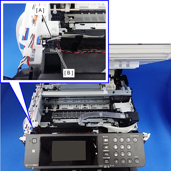
You will need to perform the Head angular mecha adjustment with the ADF/SCN Unit opened. For this, to put the ADF/SCN open sensor (A) in a closed state, perform the Head angular mecha adjustment with the ADF/SCN open sensor (A) fixed by tape (B).
|
Procedure
- Start service support mode. (Starting Service Support Mode)
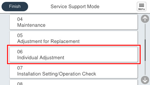
- Select [06 Individual Adjustment].
- Select [601 Printer/Additional Cassette].
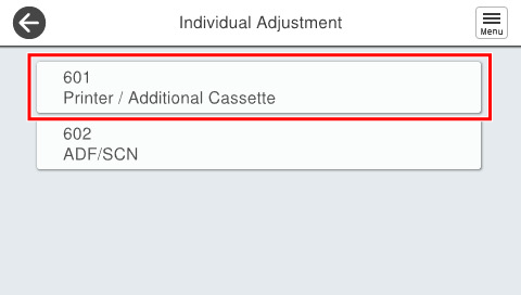
- Select [60115 Head Angular Adj. (H/W)].
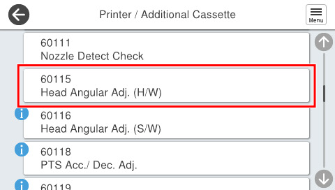
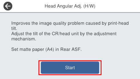
- If the following screen is displayed, press [Execute].
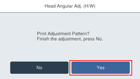
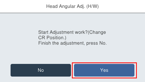
If the following screen is displayed, press [Yes].
- Press each setting item button to confirm print settings.
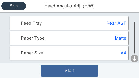
Setting Items Choice Remarks Feed Tray Rear ASF Setting change not possible Paper Type Matte Paper-Heavy weight/Premium Presentation Paper Matte Setting change not possible Paper Size A4 Setting change not possible - Set matte paper (A4) to the rear ASF and press [Start]. Adjustment patterns are printed on 1 sheet.
- Adjustment pattern
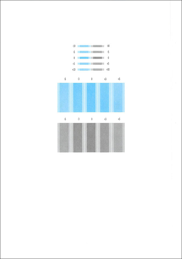
- Adjustment pattern
Check the adjustment pattern and determine the adjustment value based on the judgment procedure.
Check Point / チェックポイント- Adjustment pattern
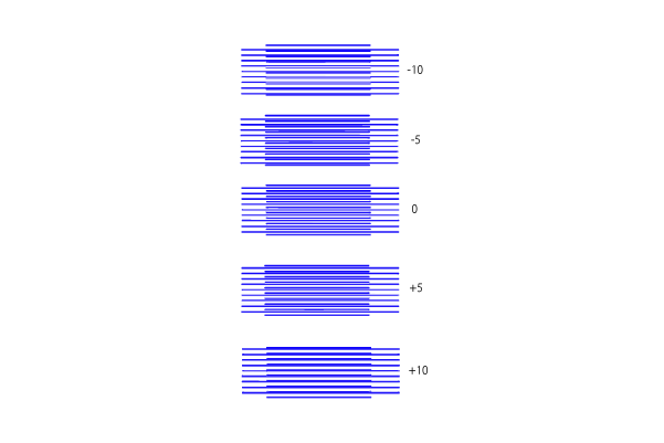
- Printed with a rough adjustment pattern: adjustment interval values of five staggered intervals (-10, -5, 0, +5, +10).
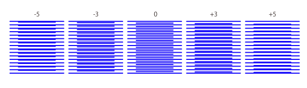
- Printed with a detailed adjustment pattern: adjustment interval values of three staggered intervals (-5, -3, 0, +3, +5).
- Printed with a rough adjustment pattern: adjustment interval values of five staggered intervals (-10, -5, 0, +5, +10).
- Adjustment value judgment method
- The interval of the pattern lines will be adjusted so that it is most equal when the adjustment value is “0.”
- Adjustment pattern
- After the adjustment pattern is printed, the following confirmation screen will be displayed. When adjustment is necessary, press [Yes]. After operation, the CR unit moves to the center part of the printer.
 Caution / 注意
When the tape for the ADF/SCN open sensor is disconnected during adjustment, since there is a risk when the CR Unit moves to the home position, be sure that it is securely fixed.
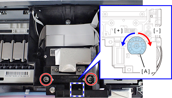
Remove the screws (x2) that fix the Head Upper Cover and remove the Head Upper Cover.
Turn the head screws (x3) that fix the Print Head
 counterclockwise by 90º to loosen them.
- Based on the adjustment value confirmed in step 9, turn the head angular adjustment dial (A) of the CR Unit.
 Check Point / チェックポイント
When the head angular adjustment dial of the CR Unit has been turned before, rotate only one gradation.
- Tighten the head screws (x3).
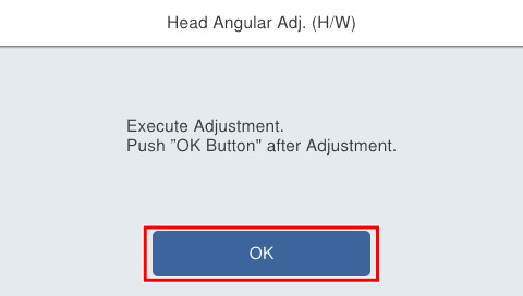
- Press [OK] on the following screen.
- Press [Execution].
Press each setting item button to confirm print settings.
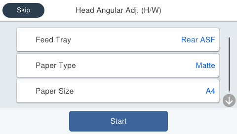
Setting Items Choice Remarks Feed Tray Rear ASF Setting change not possible Paper Type Matte Paper-Heavy weight/Premium Presentation Paper Matte Setting change not possible Paper Size A4 Setting change not possible Set matte paper (A4) to the rear ASF and press [Start]. The adjustment patterns are printed.
- Repeat Step 9 through Step 18 until the lines of adjustment pattern “0” are most equal.
| Caution / 注意 |
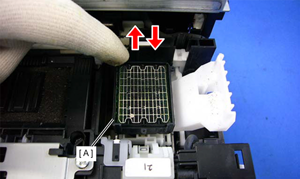
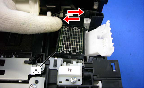
After carrying out a head angular adjustment, make sure to confirm the operation of the follow-up mechanism of the cap of the ink system Assy by the following procedure.
|