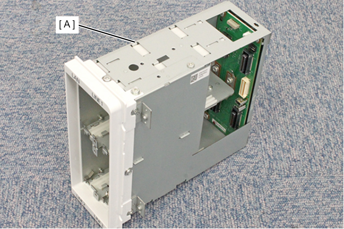
I/F Port Unit
- Remove the three screws, then remove the Left Housing Assy (A) toward the rear of the product.
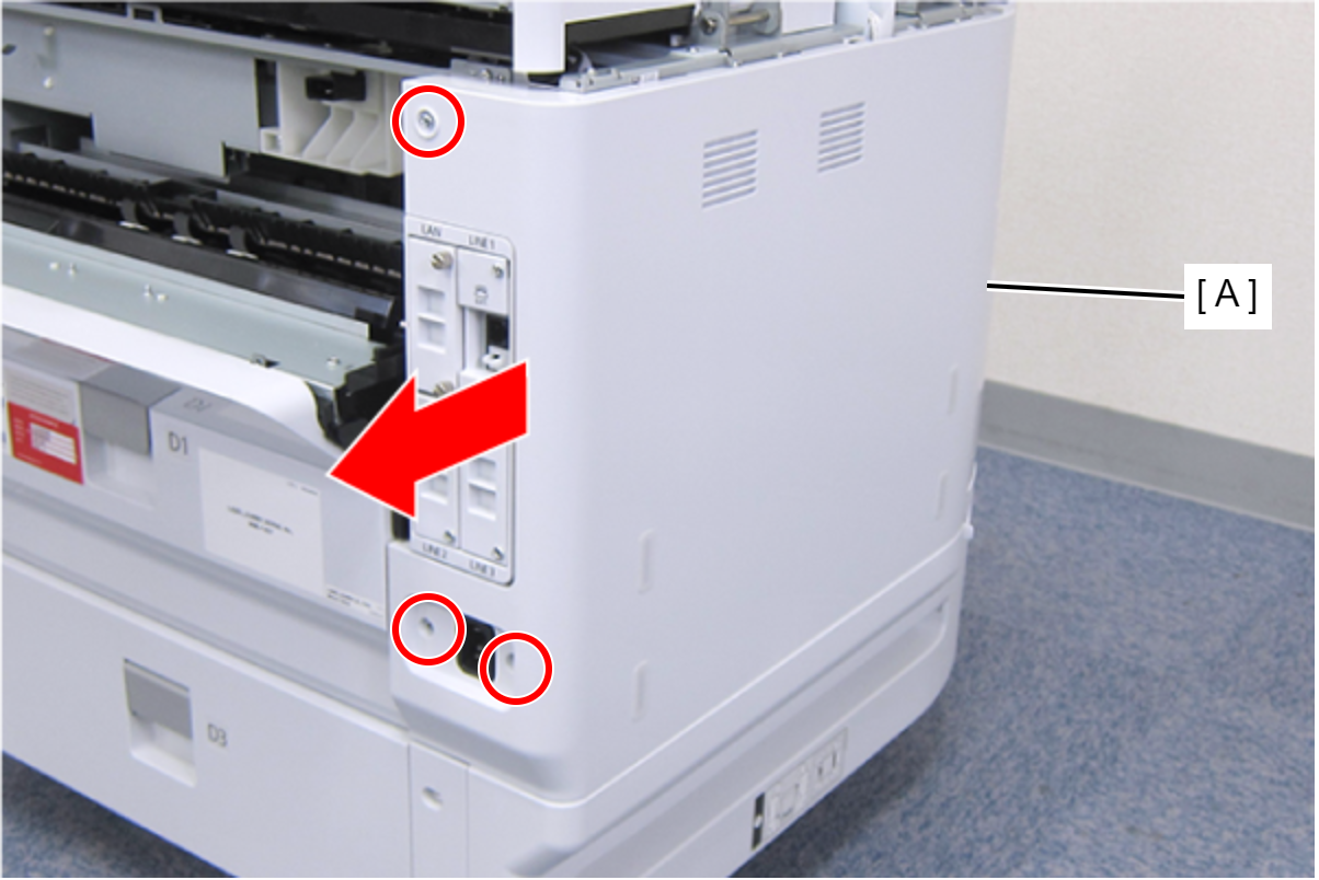
 : C.B.S-TITE-SCREW-3x8-F.ZN-3C
- Remove the two screws, and remove the I/F Housing Bracket (A).
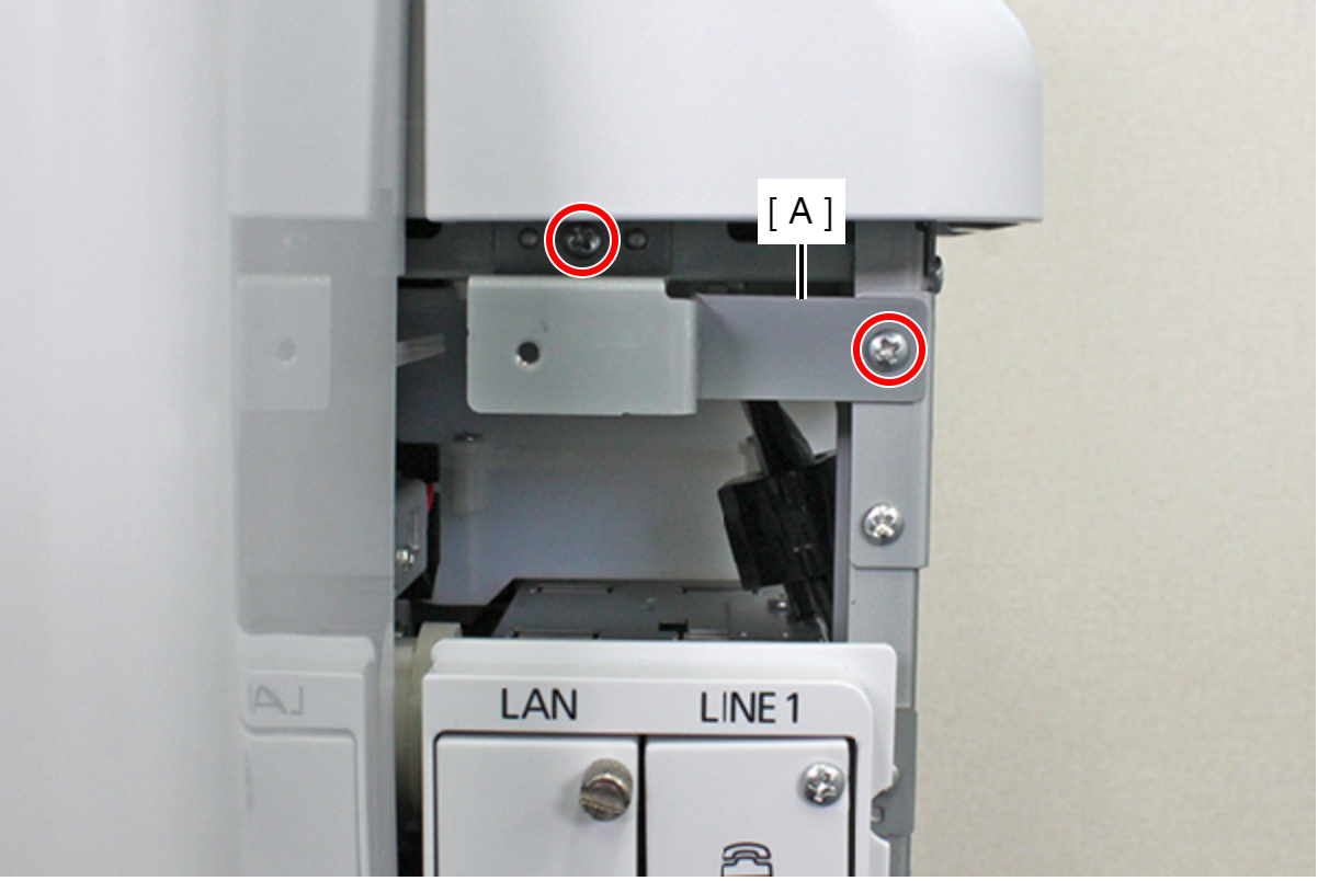
- : C.B.S-TITE-SCREW-3x8-F.ZN-3C
- Remove the two screws, then remove the Rear ASF Unit (A).
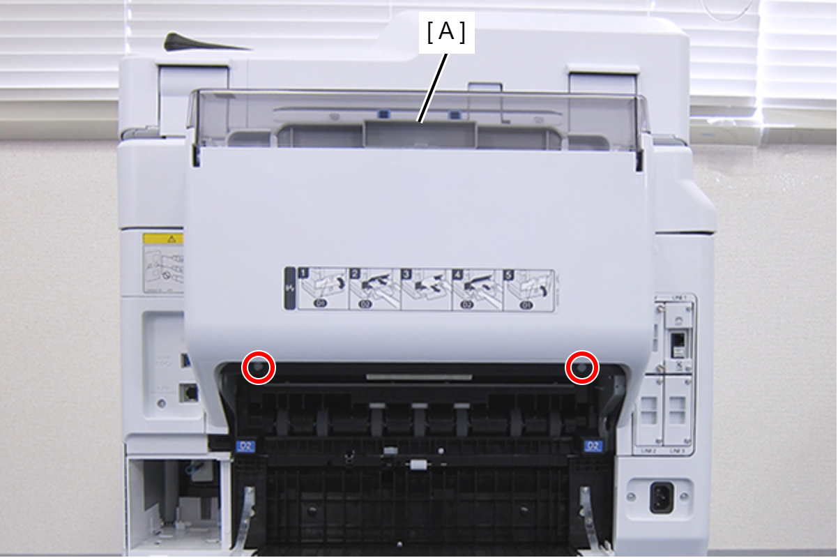
- : C.SHOULDER S-TITE,3X5
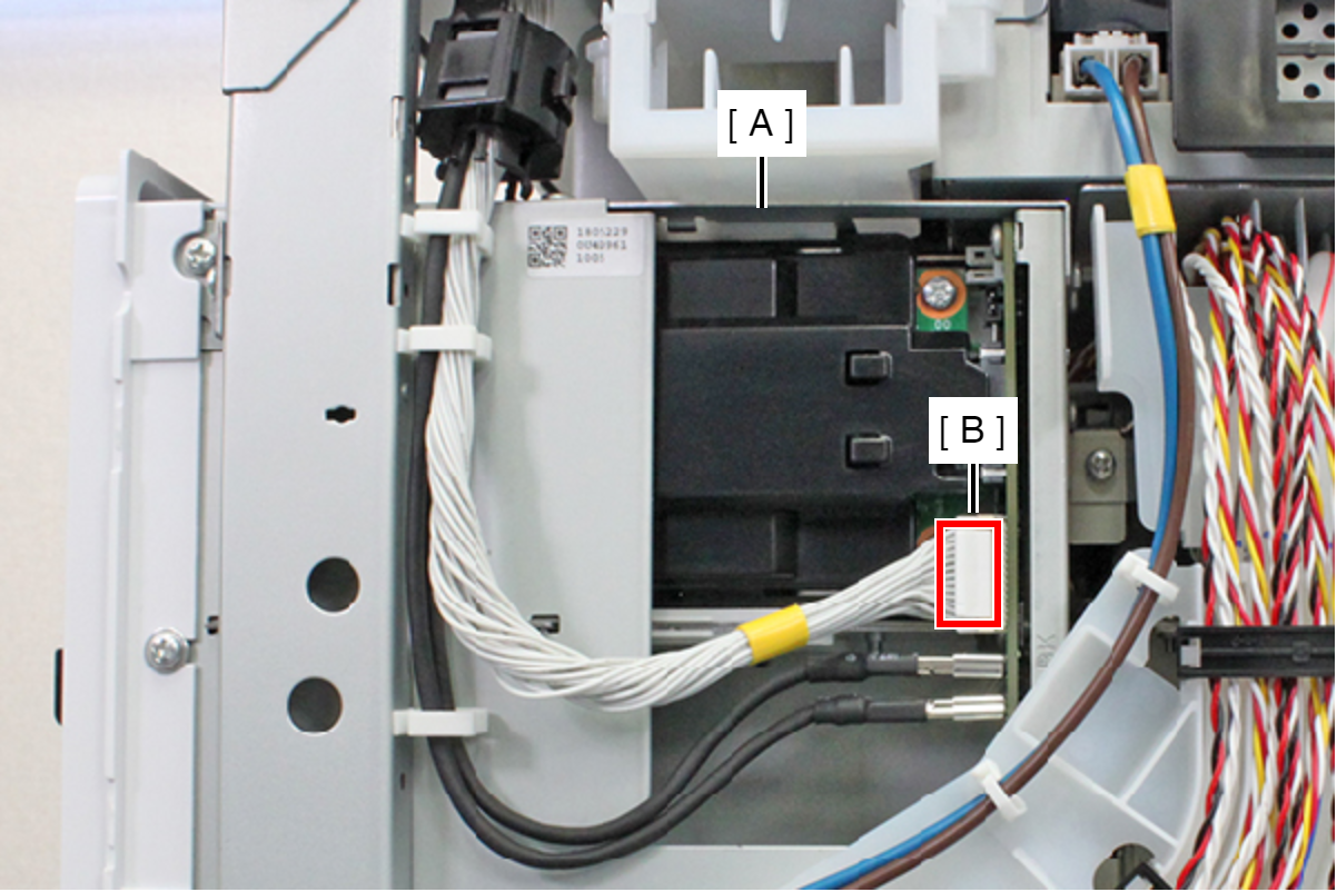
Remove the cable from the connector (CN7) (B) of the I/F Port Assy (A) while releasing the hook.
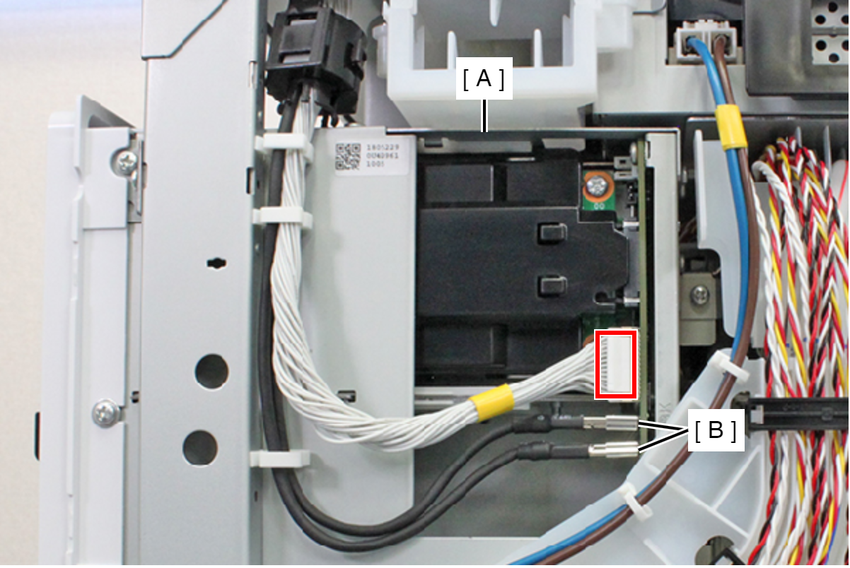
- Remove the cable from the connectors (CN5, CN6) (B) of the I/F Port Assy (A).
- Remove the four screws, and remove the I/F Port Assy (A).
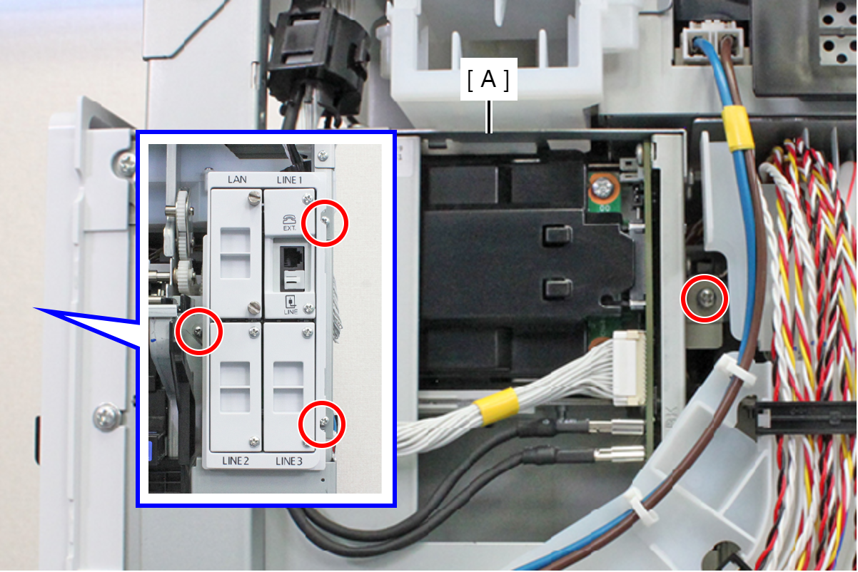
- : C.B.S-TITE-SCREW-3x8-F.ZN-3C
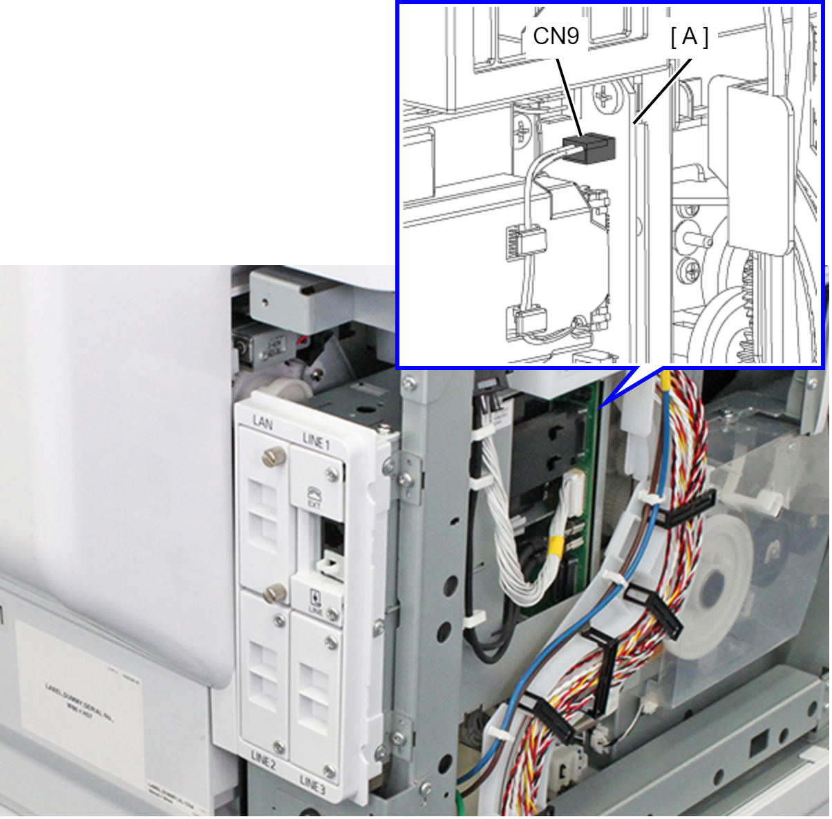
- Disconnect the cable from the connector (CN9) on the I/F Port Board.
- Remove the two screws, and remove the FAX Assy (A).
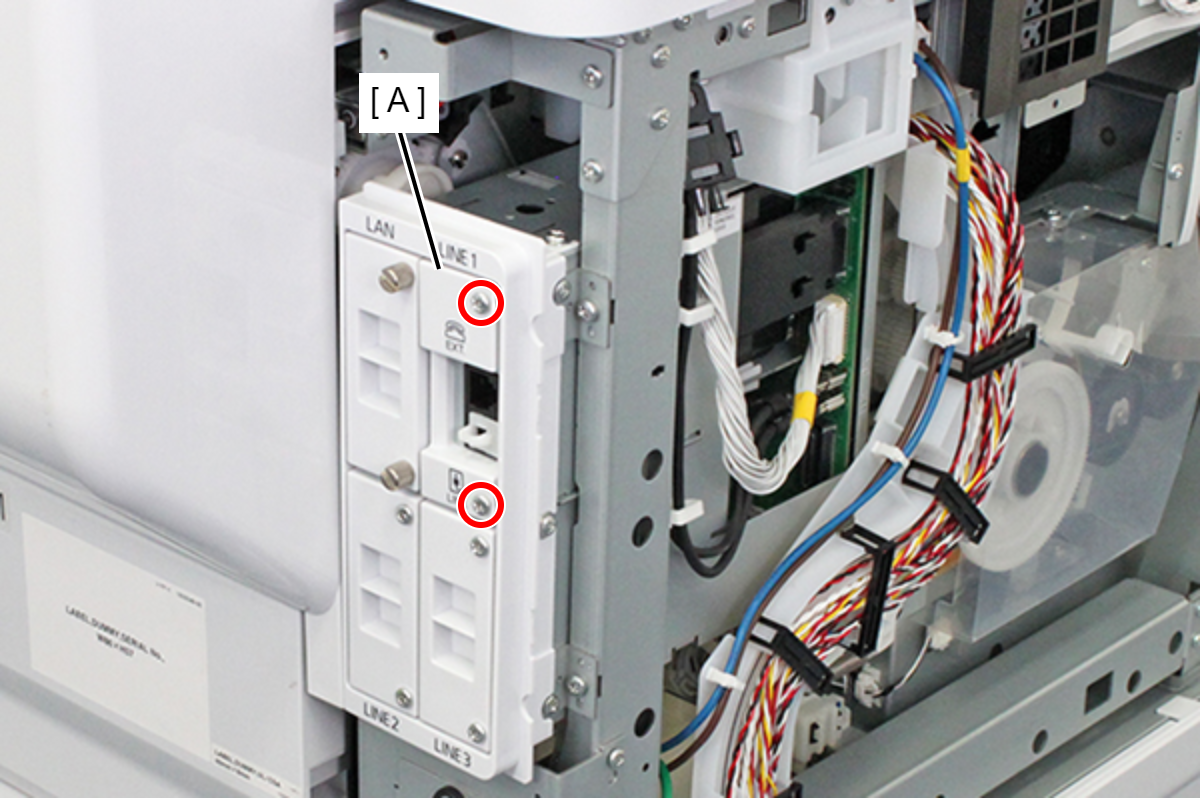
- : C.B.S-TITE-SCREW-3x14-F.ZN-3C
- Remove the two screws, and remove the I/F FAX Cover Assy (A).
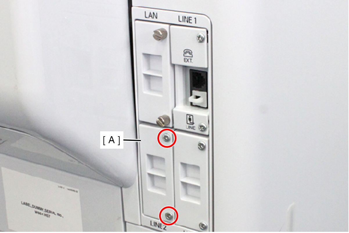
- : C.B.S-TITE-SCREW-3x14-F.ZN-3C
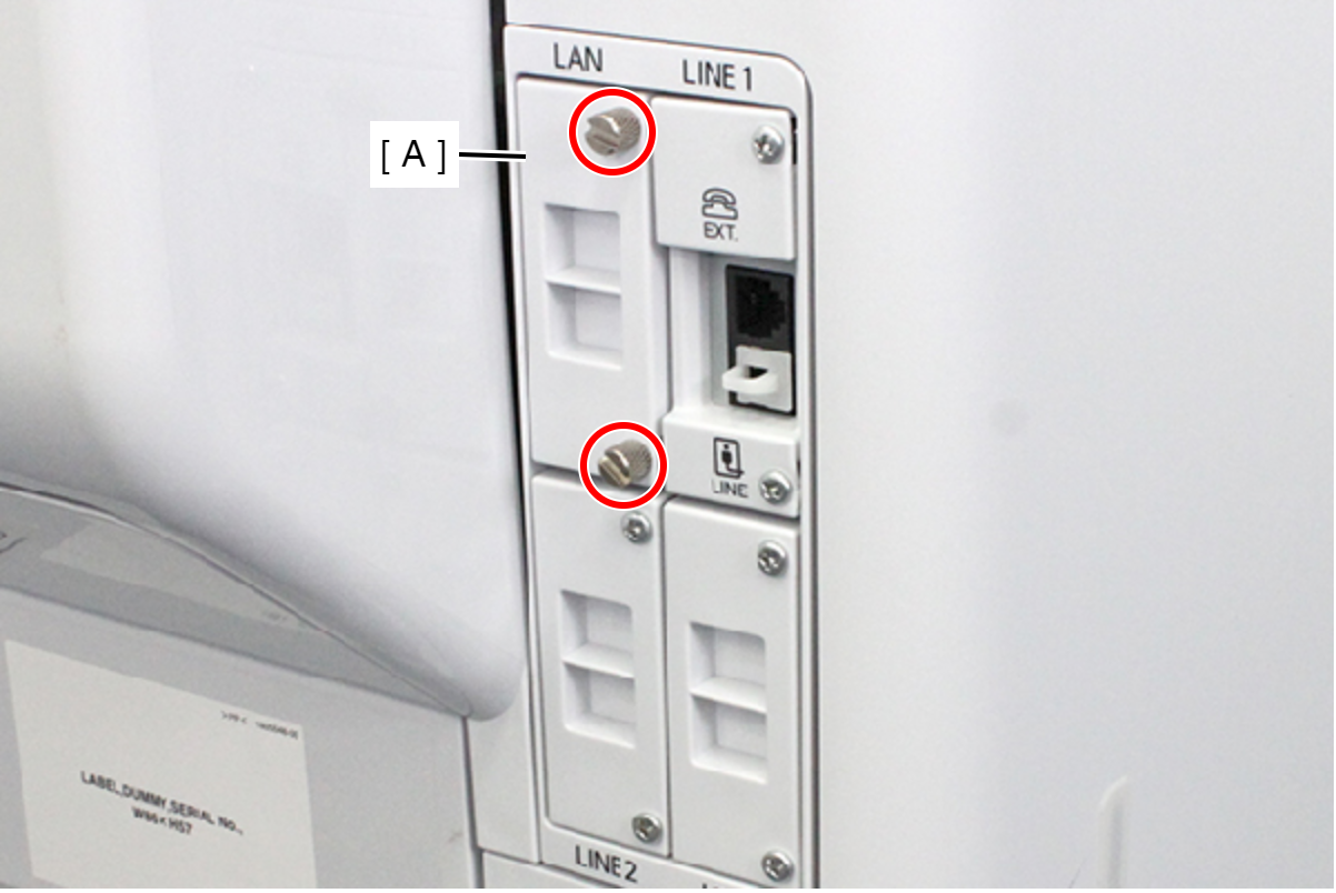
- Rotate the two screws fastening the I/F Option Cover Assy (A) until they completely spin freely.
Remove the I/F Option Cover Assy (A).
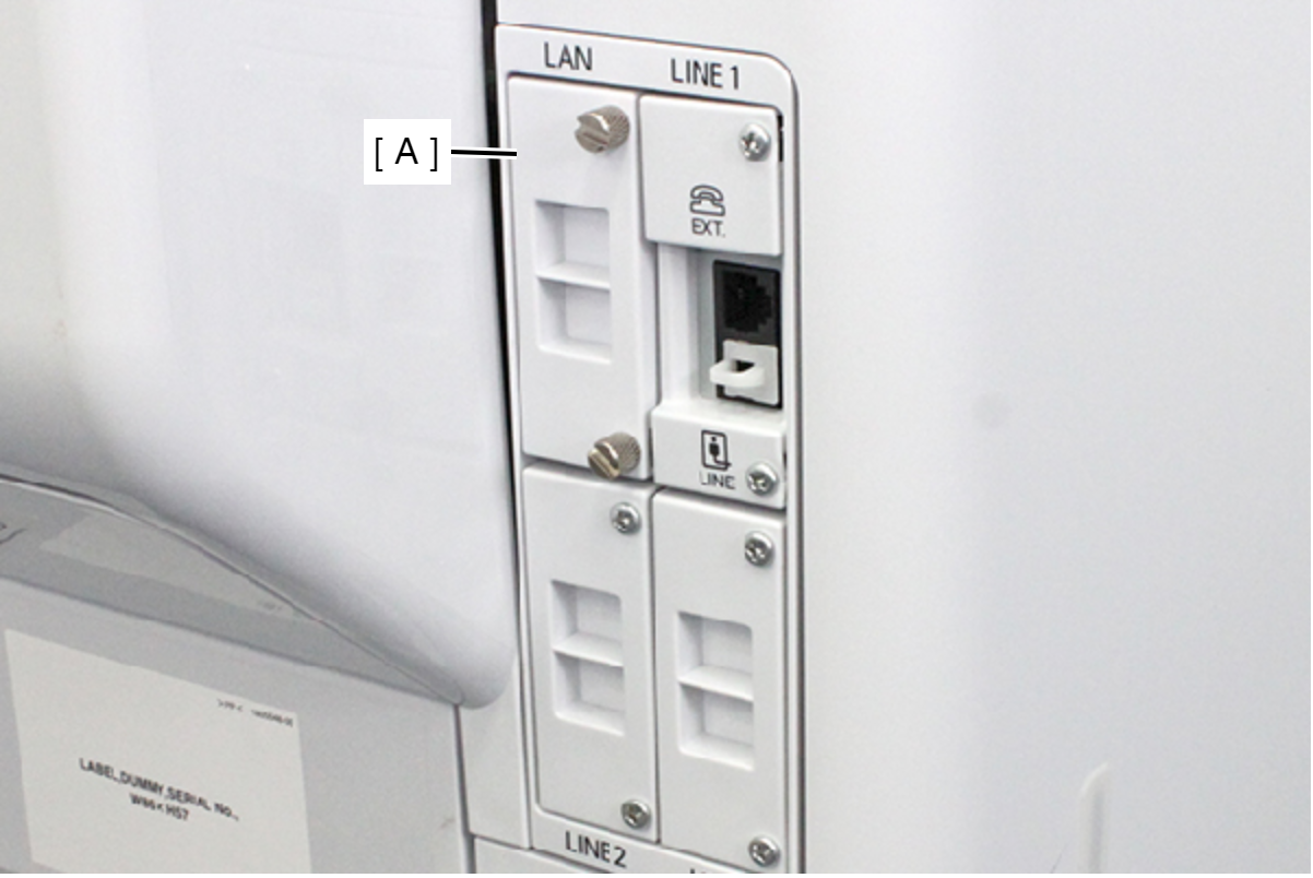
 Check Point / チェックポイント
Because the screws are captive screws, they do not come off.
- Remove the I/F Port Unit (A).