
Print Head
 Adjustment / 調整 Adjustment / 調整 |
When replacing this part, you need to run the menu from the service support mode before replacing it. When removing or replacing the print head, be sure to check the following page and perform the procedures, including the adjustments. |
- Remove the two screws.
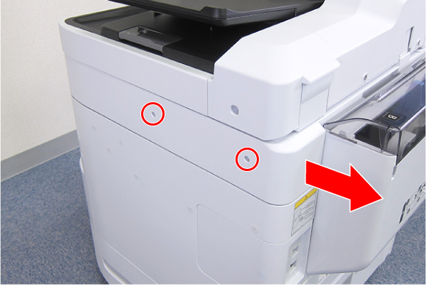
 : C.B.S-TITE-SCREW-3x8-F.ZN-3C
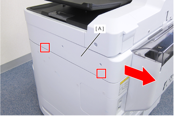
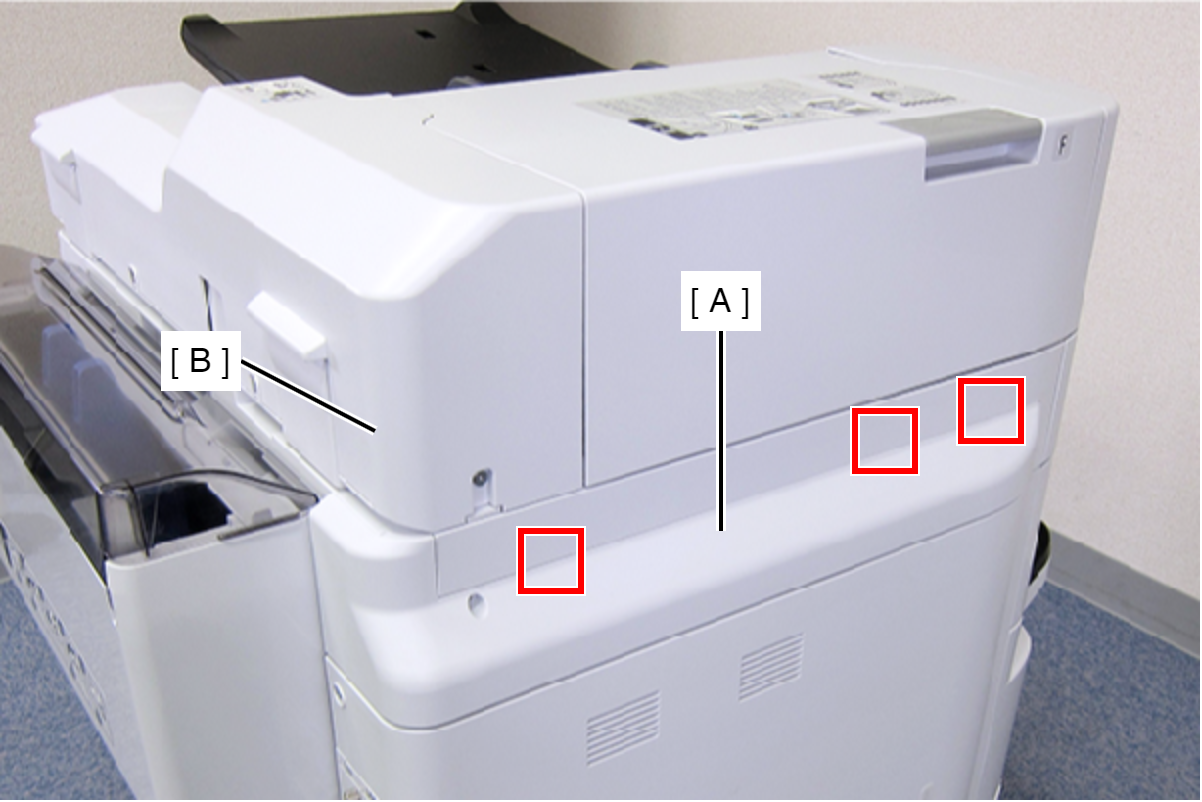
- Disengage the two hooks by sliding the Right SC Cover (A) toward the rear of the product, then remove it.
- Remove the screw.
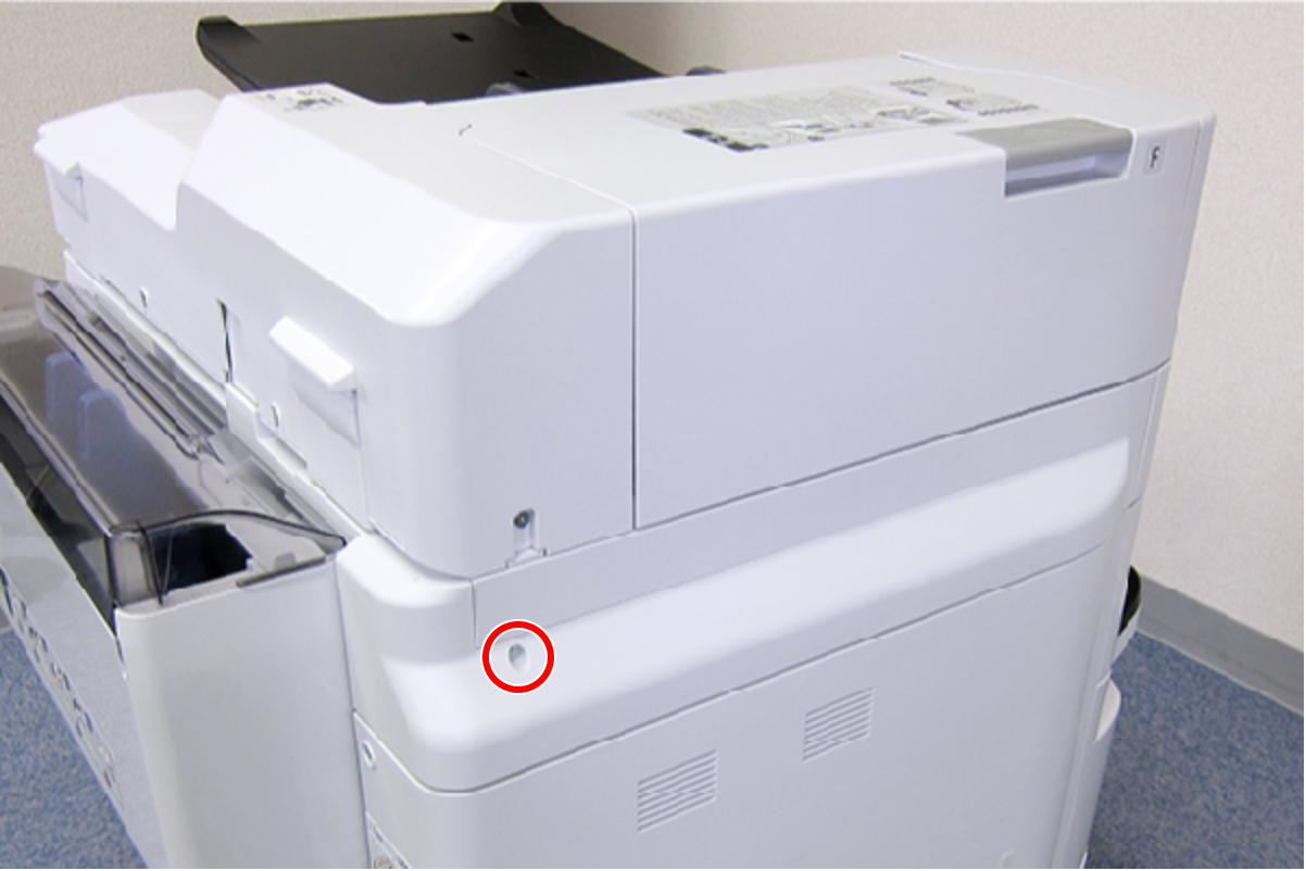
- : C.B.S-TITE-SCREW-3x8-F.ZN-3C
- Slide the Left SC Cover (A) toward the rear of the product to disengage the tab.
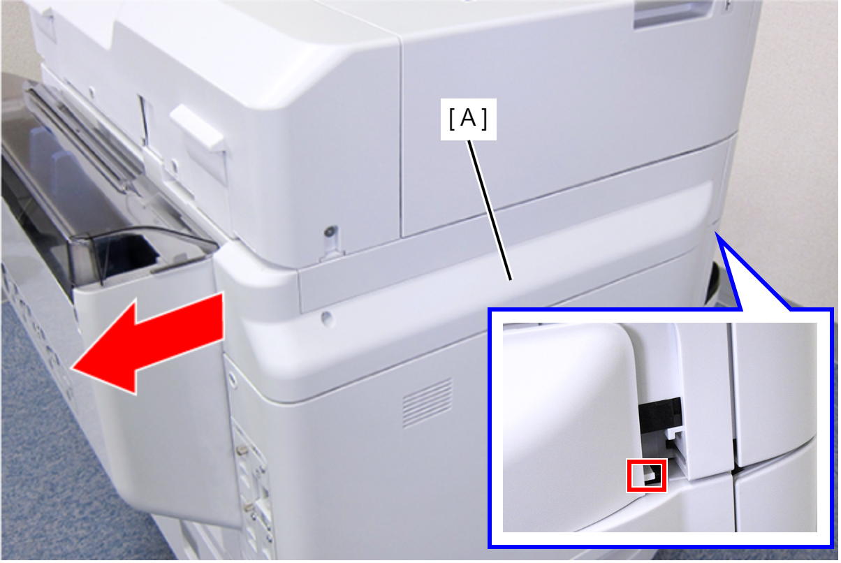
- Disengage the three tabs by inserting a flathead screwdriver into the gap between the Left SC Cover (A) and the ADF Unit (B), and then remove the Left SC Cover (A).
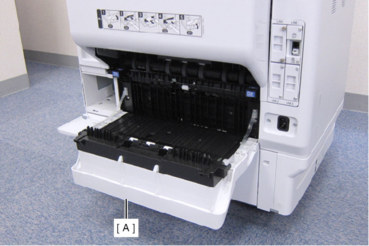
- Open the Duplex Print Cover (A).
- Remove the two screws, then remove the Connector Cover (A).
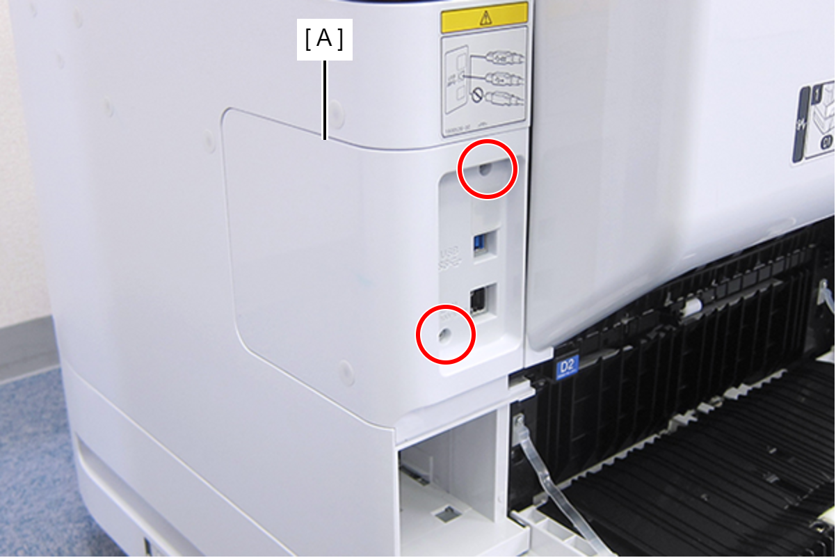
- : C.B.S-TITE-SCREW-3x8-F.ZN-3C
- Remove the two screws, then remove the Right Housing Assy (A) toward the rear of the product.
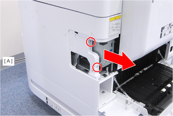
- : C.B.S-TITE-SCREW-3x8-F.ZN-3C
- Remove the two screws.
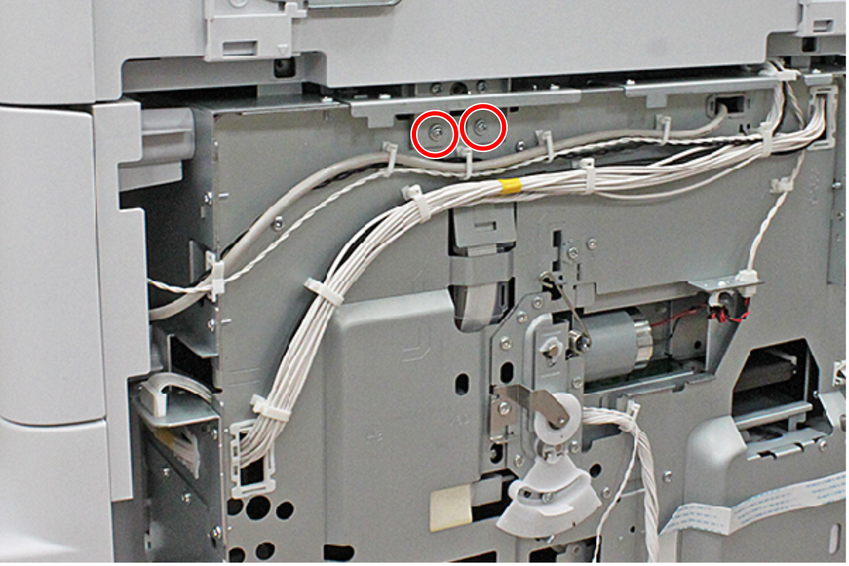
- : C.C.S-TITE-3x6-F.ZN-3C
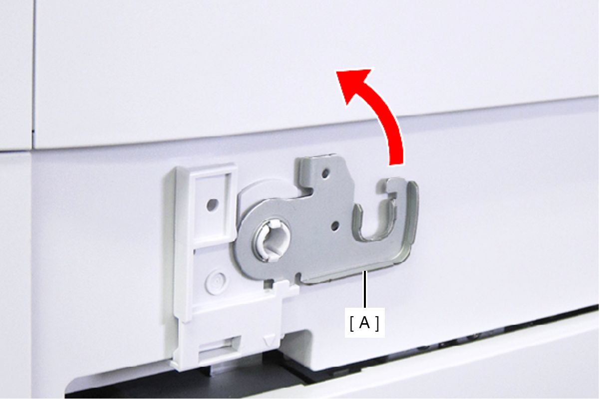
- Raise the ADF Stopper (A) to lock the ADF Unit.
- Secure the ADF Stopper with one of the screws you removed at step 1.
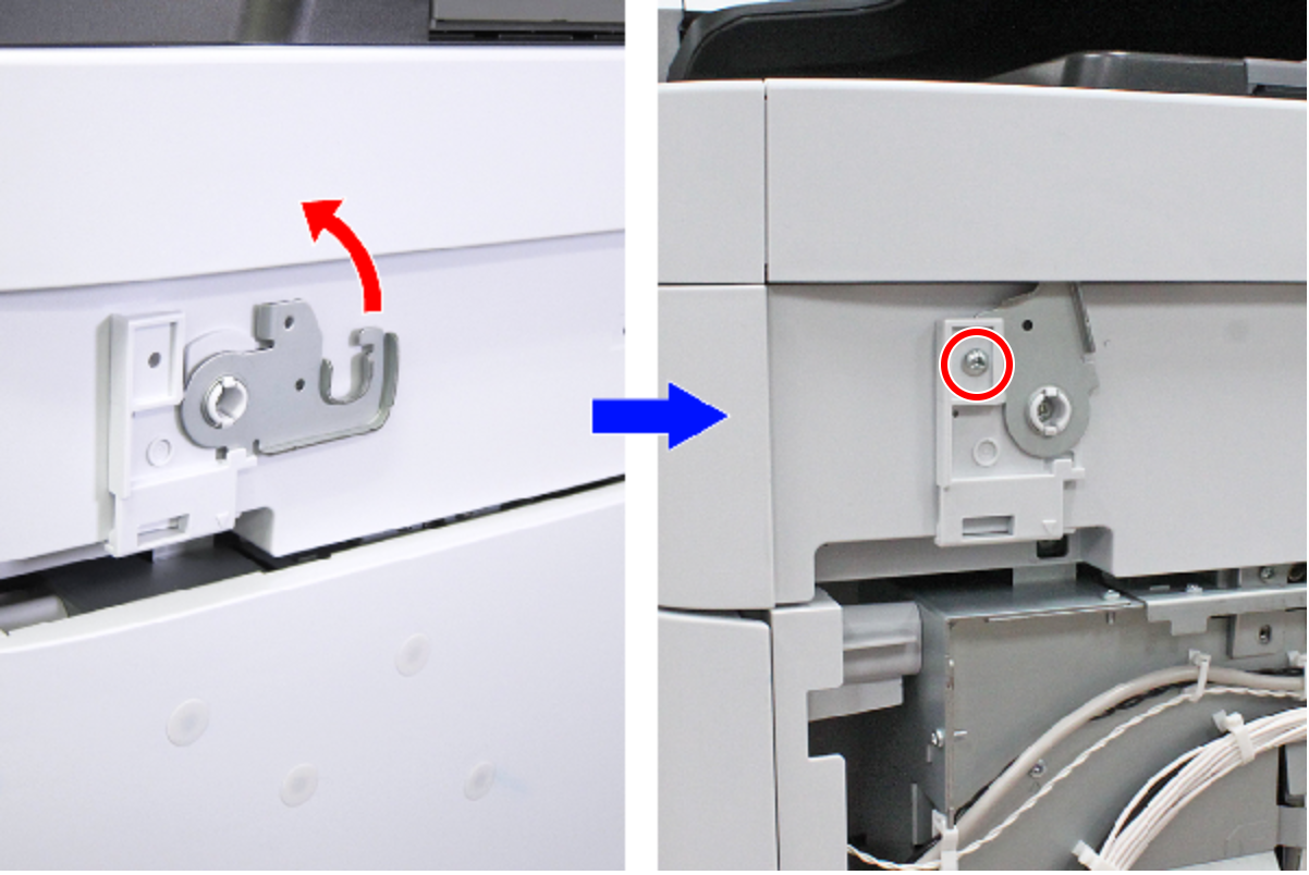
- : C.C.S-TITE-3x6-F.ZN-3C
- Hold the ADF/SCN Unit (A) with both hands as shown above, and open the ADF/SCN Unit (A).
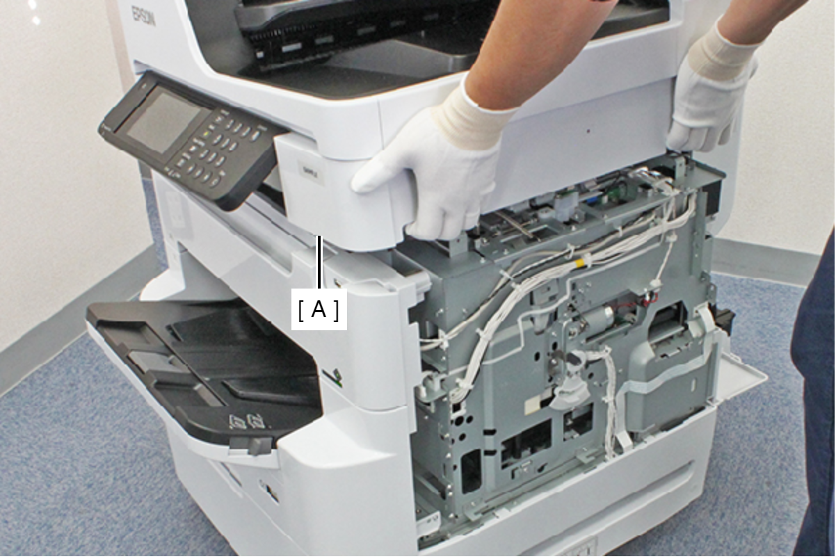
- Open the ADF/SCN Unit (A) and extend the support stand (B) as far as it goes, then support theADF/SCN Unit (A) with the support stand.
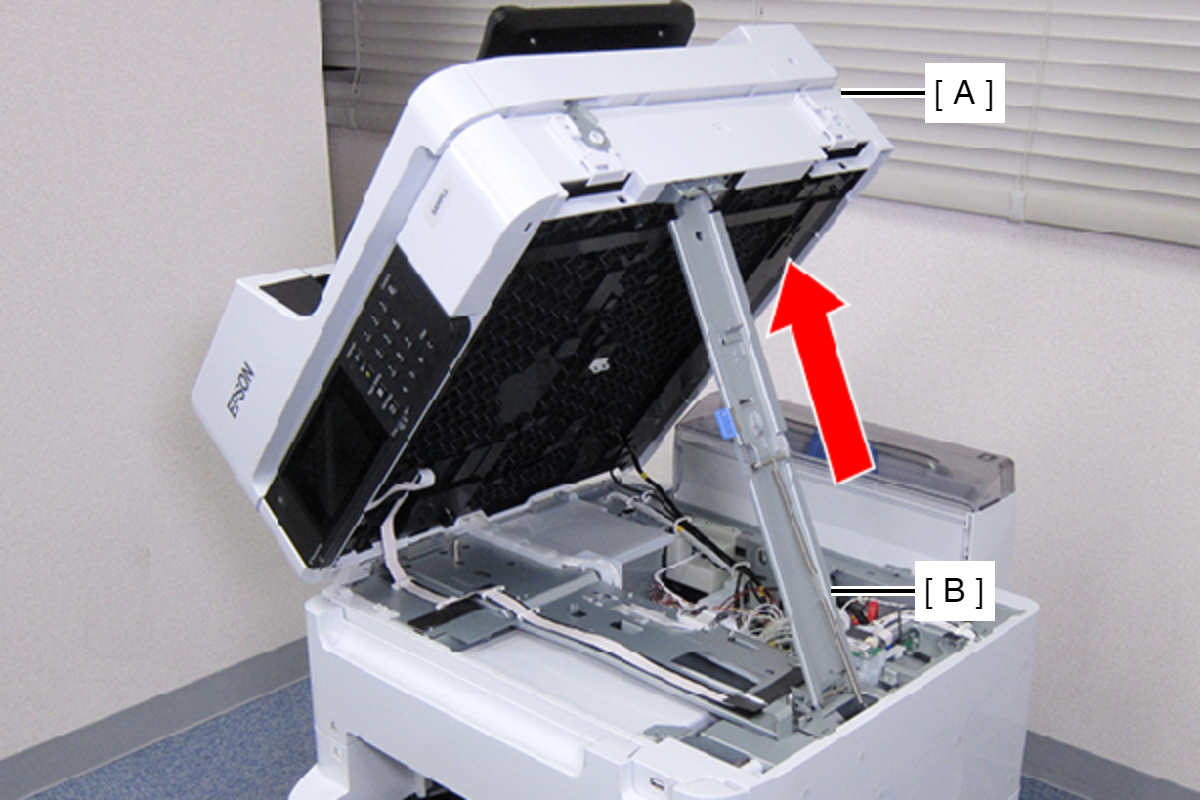
 Caution / 注意
Make sure that the extended support stand is fixed with the two hooks, and the two triangle marks face to each other.
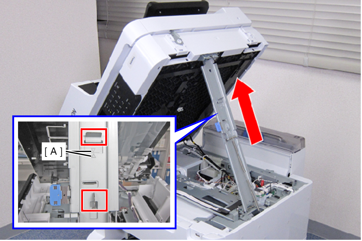
 Check Point / チェックポイント
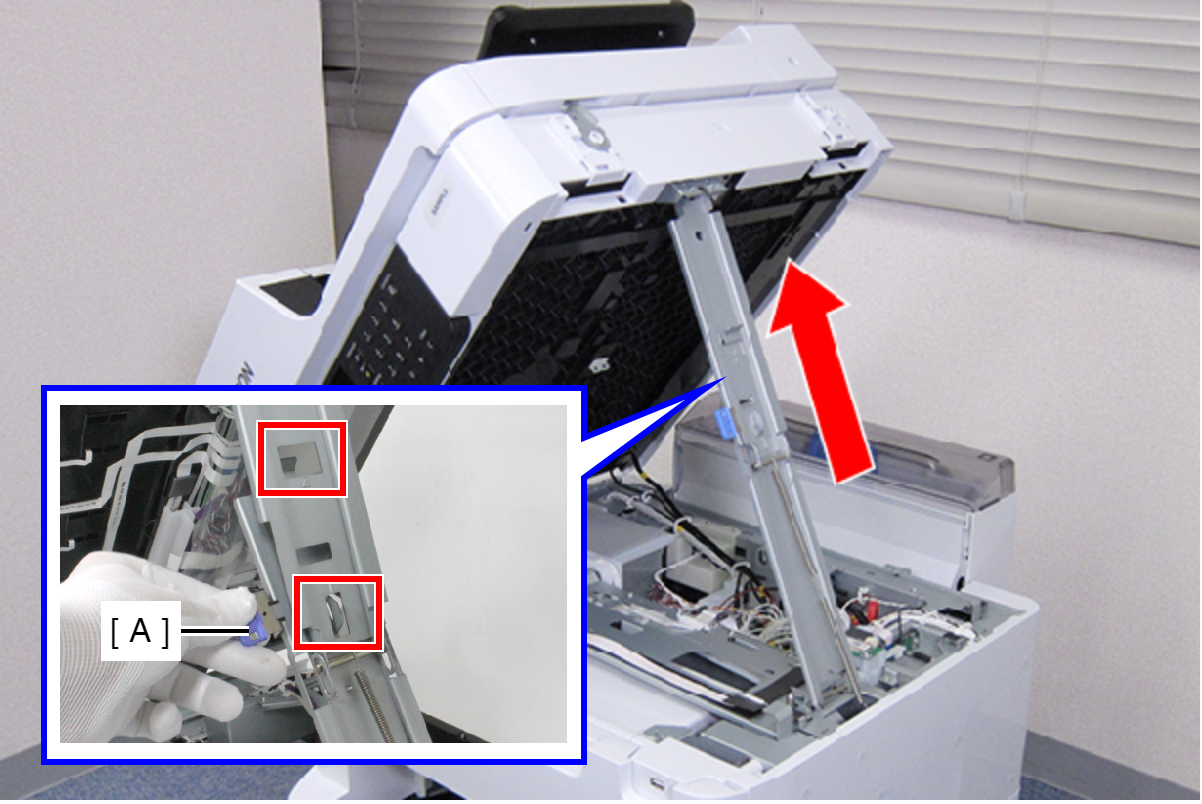
When closing the ADF/SCN Unit, hold down the switch on the support stand and raise the ADF/SCN Unit in the direction of the arrow to disengage the two hooks, then fold the support stand.
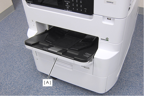
- Remove the Stacker Assy (A).
- Open the Front Cover Assy (A).
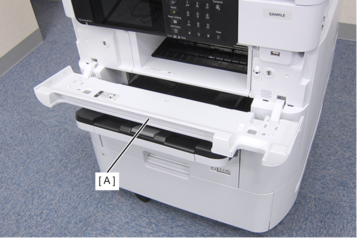
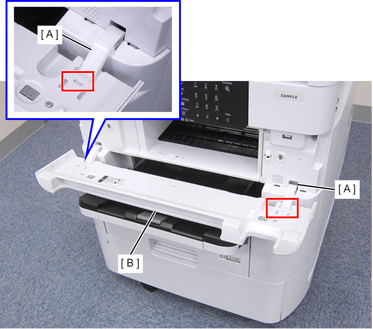
- While pressing the two hooks of the hinge (A), remove the Front Cover Assy (A) frontward.
- Remove the four screws, then remove the Front Inner Housing Center (A) frontward.
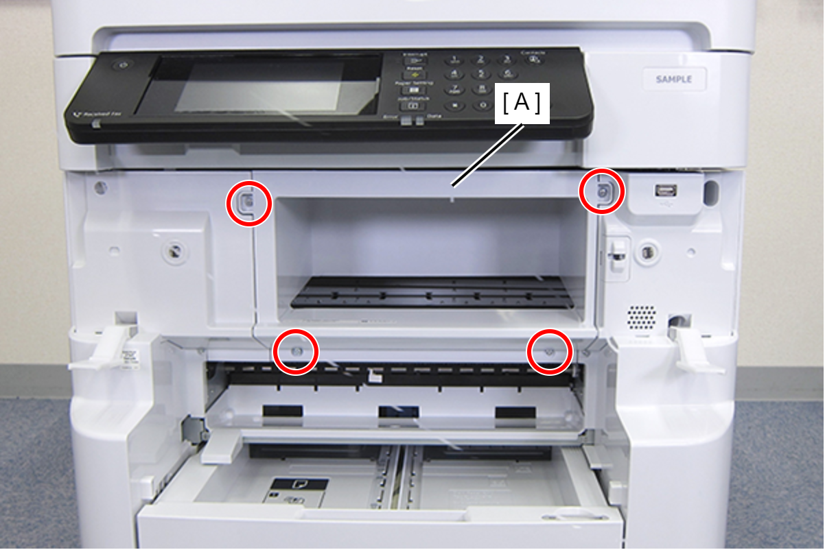
- : C.B.S-TITE-SCREW-3x8-F.ZN-3C
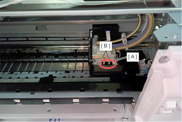
- Remove the two Air Tubes (B) connected to the Print Head (A) side.
- Remove the three screws that secure the Self-Sealing Unit (A).
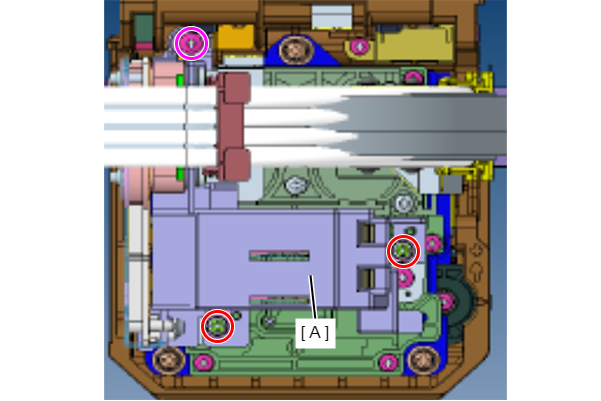
 : C.B.S2-3x12-F.ZN-3C
 : C.B.P-TITE-SCREW-2.5x10-F.ZN-3C
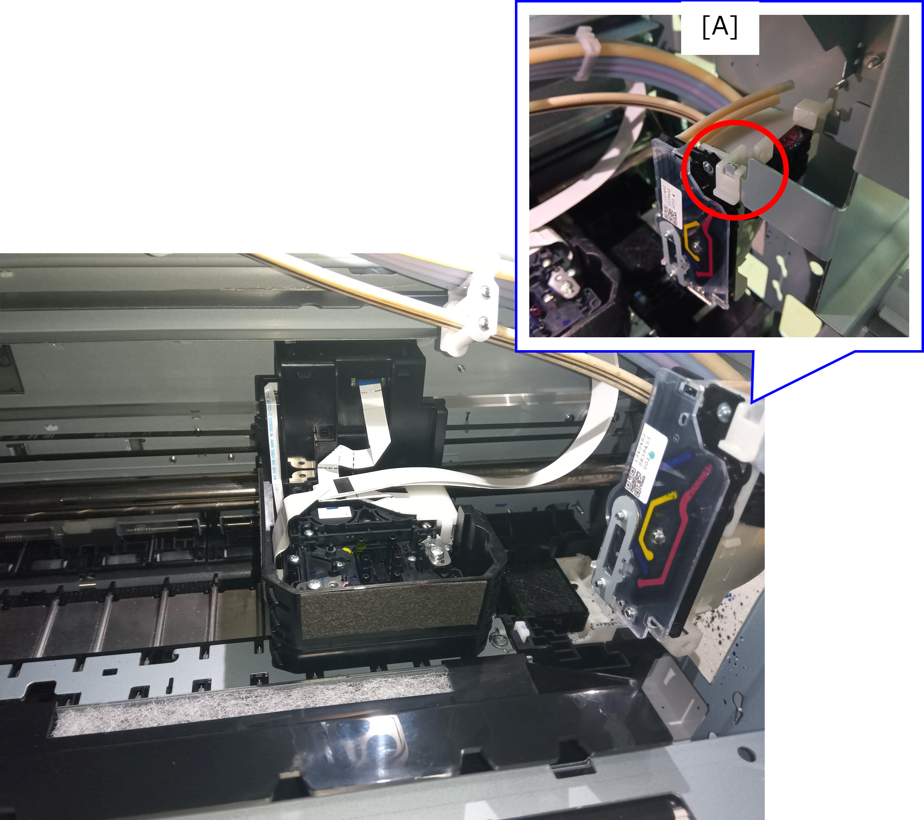
Remove the Self-Sealing Unit.
Caution / 注意Be sure to move the Self-Sealing Unit straight up to remove it.
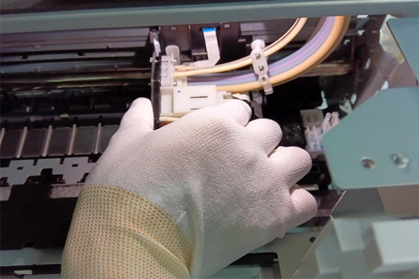
- Hook the Self-Sealing Unit to the hook (A) on the frame.
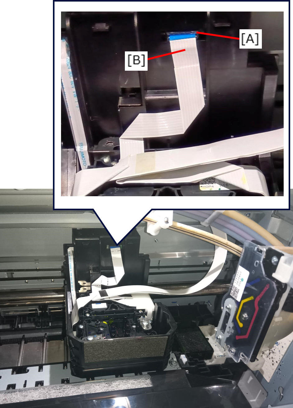
- Disconnect the FFC (B) from the connector (A) of the CR encoder sensor.
- Remove the three screws, then remove the Print Head (A).
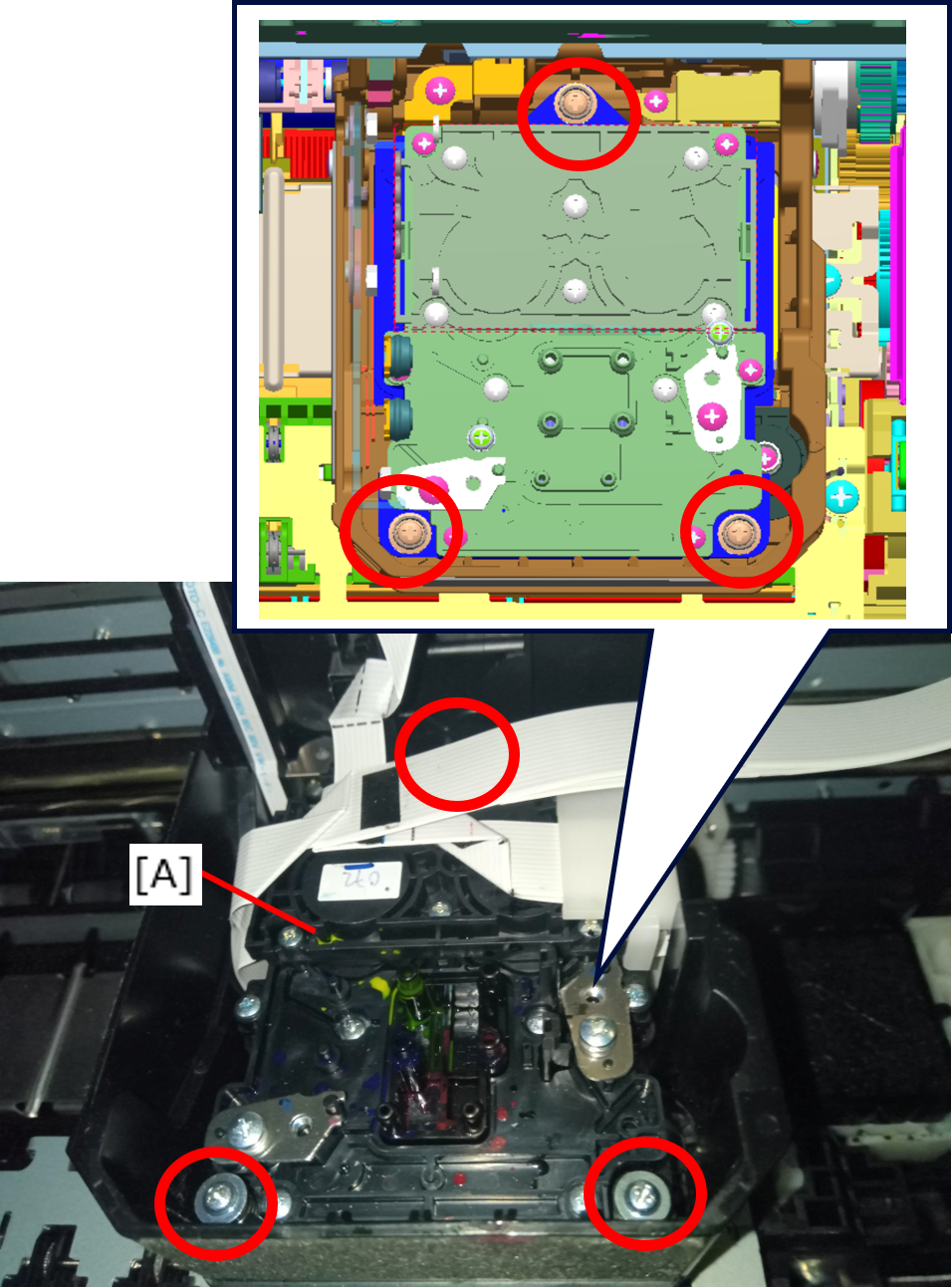
- : SCREW,MOUNT,HEAD,ASSY
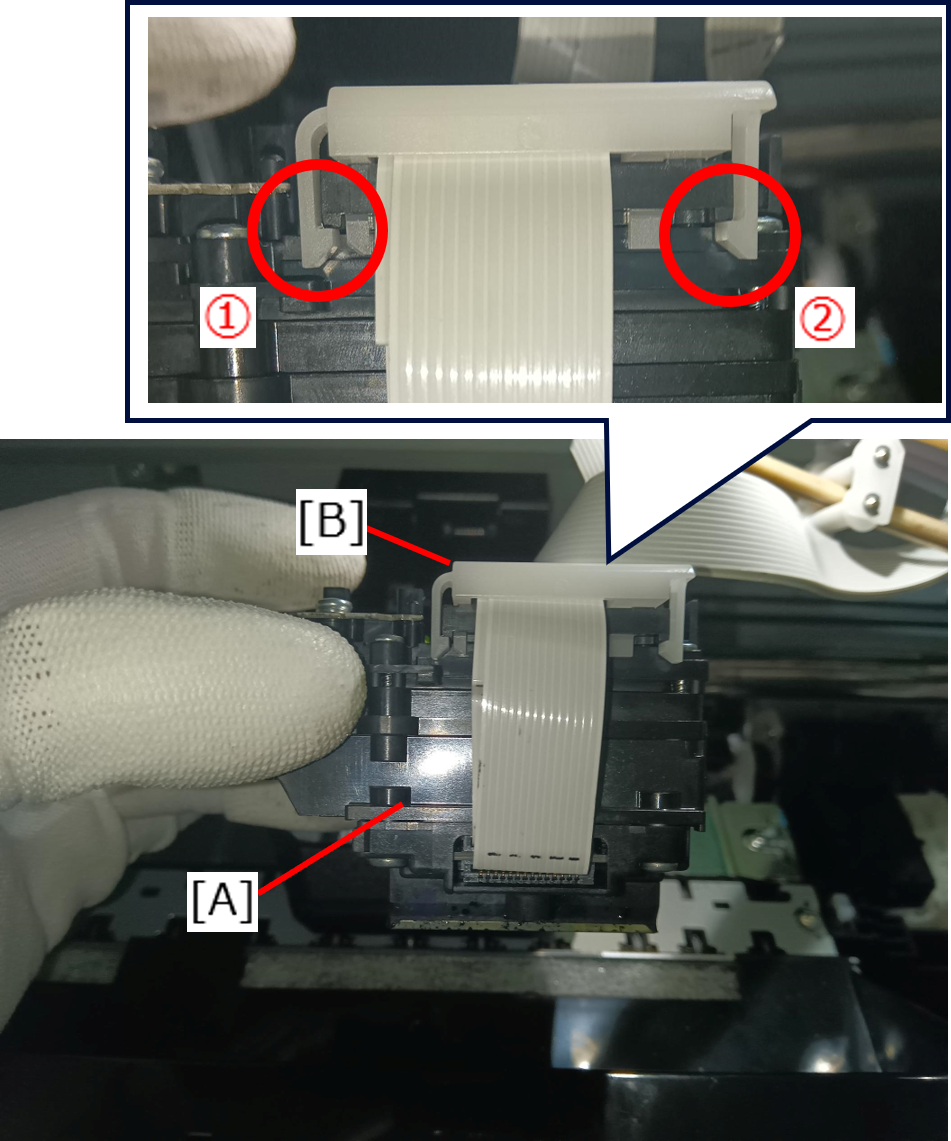
Follow the removal order to remove the two hooks and then remove the FFC fixing clamp (B) from the Print Head (A).
 Caution / 注意
Be sure to follow the removal order.
Be careful not to break the hook.
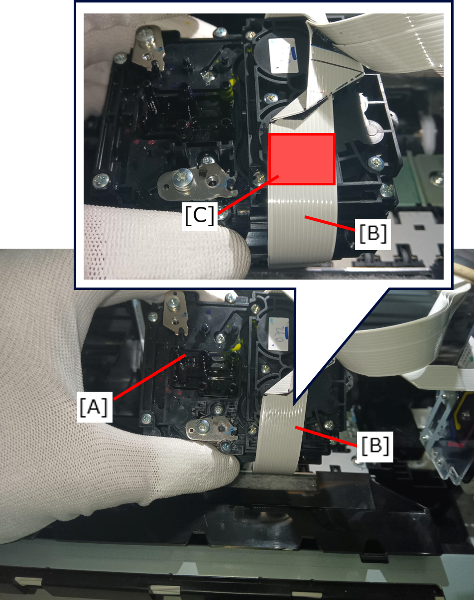
- Peel off the double-sided tape [C] that is adhering the Print Head (A) and Head FFCs (B).
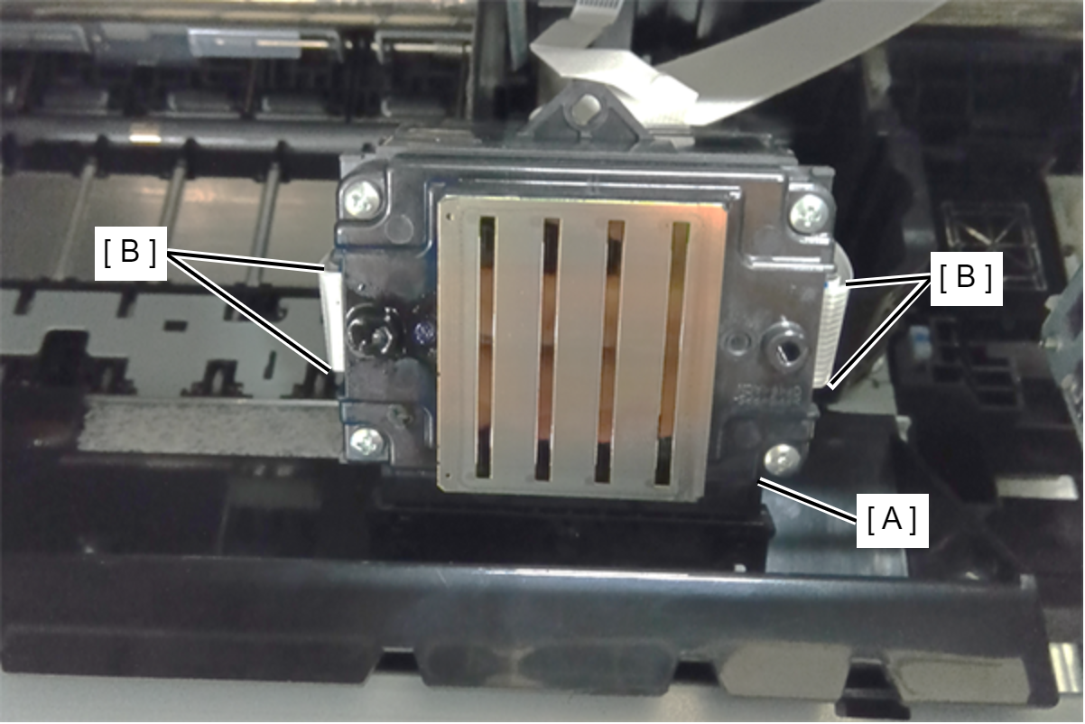
- Disconnect the four Head FFCs (B) from the connector of the Print Head (A).
 Assembly / 組み立て
Installing the Print Head
Follow the procedure below to install the Print Head.
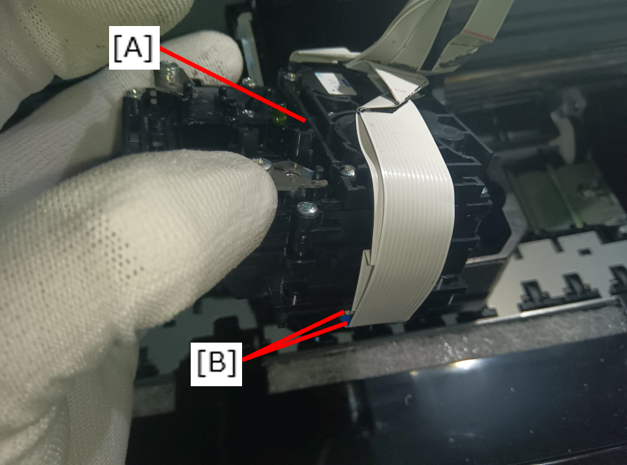
- Connect the four Head FFCs (B) to the connector of the Print Head (A).
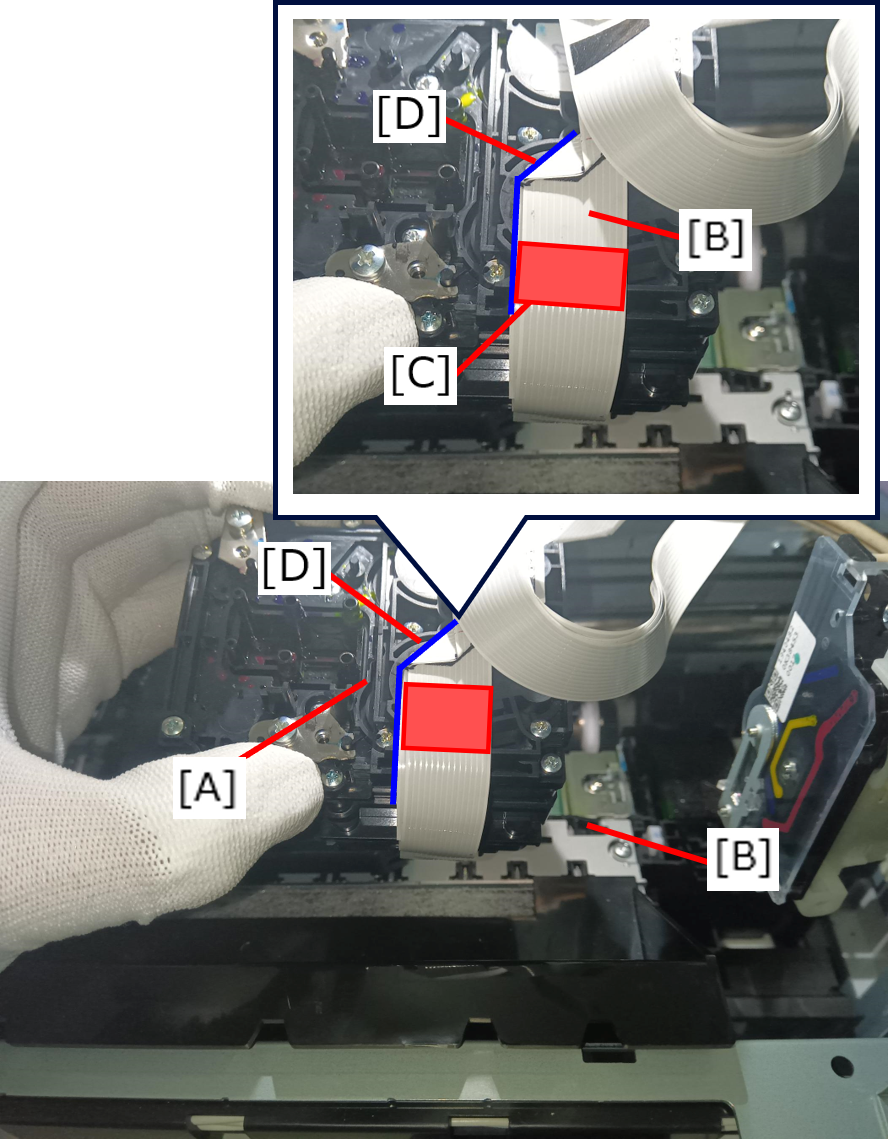
- Fix the Head FFCs (B) with the double-sided tape (C) while aligning it with the guide lines engraved on the Print Head (A).
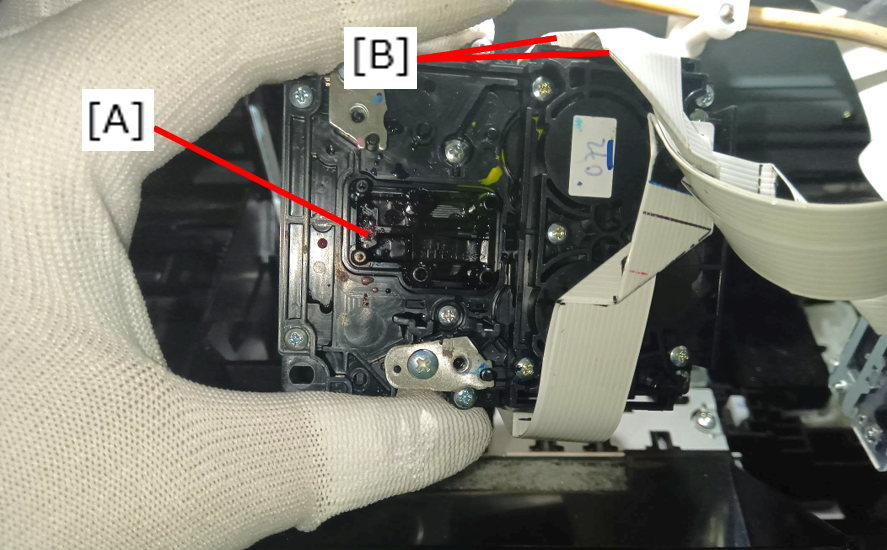
- Connect the two Head FFCs (B) (the side without double-sided tape) to the connectors of the Print Head (A).
Attach the FFC fixing clamp (B) to the Print Head (A) following the installation order.
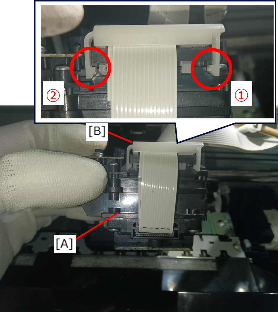 Caution / 注意
Be sure to follow the installation order.
Be careful not to break the hook.
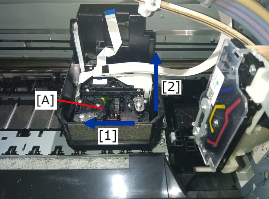
Press the Print Head (A) in the direction of the arrows in order to set it to the CR Unit.
Secure the Print Head (A) with the three screws. Tighten the screws in the order shown below.
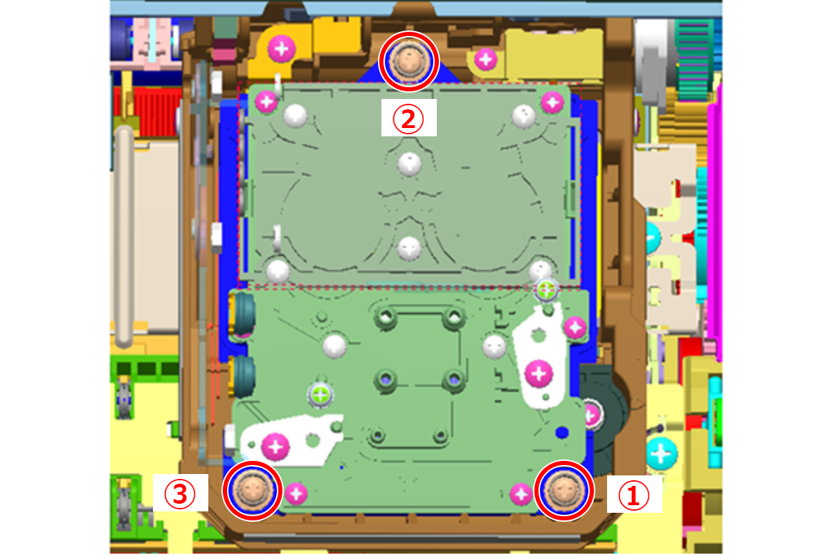
- : SCREW,MOUNT,HEAD,ASSY
- Connect the FFC (A) to the connector of the CR encoder sensor.
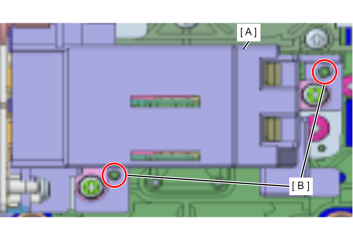
- Attach the Self-Sealing Unit (A) to the Print Head inserting the bosses into the positioning holes (B).
- Secure the Self-Sealing Unit with the three screws. Tighten the screws in the order shown below.
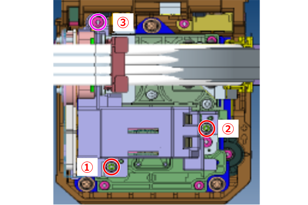
- : C.B.S2-3x12-F.ZN-3C
- : C.B.P-TITE-SCREW-2.5x10-F.ZN-3C
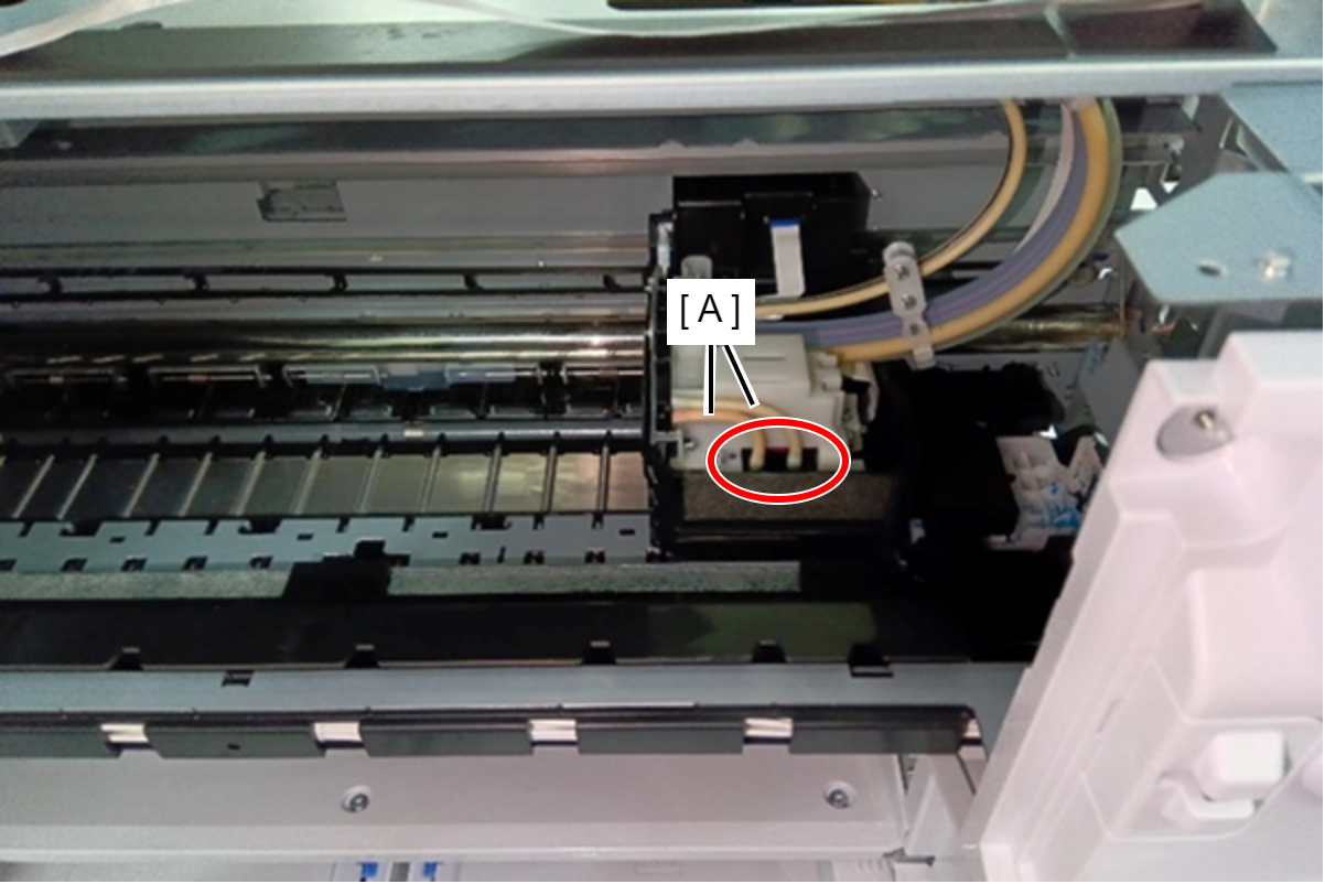
Connect the two Air Tubes (A) to the Print Head.
 Caution / 注意
When inserting the Air Tube, be sure to insert it all the way to the base of the joint.
The line marked on each of the tubes must be visible when viewed from the front side of the printer. (tolerance: ±45°)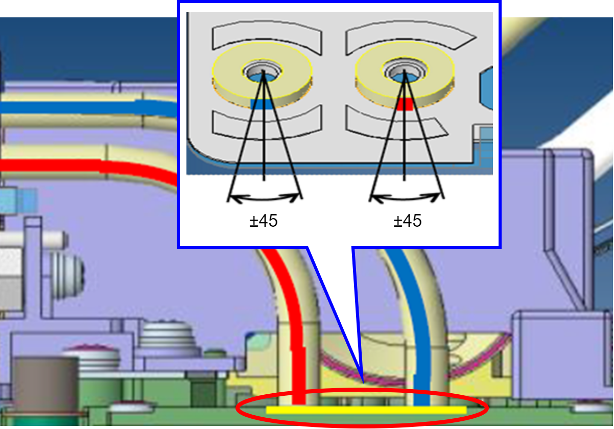
Assembly / 組み立てConfirmation after replace the Print Head
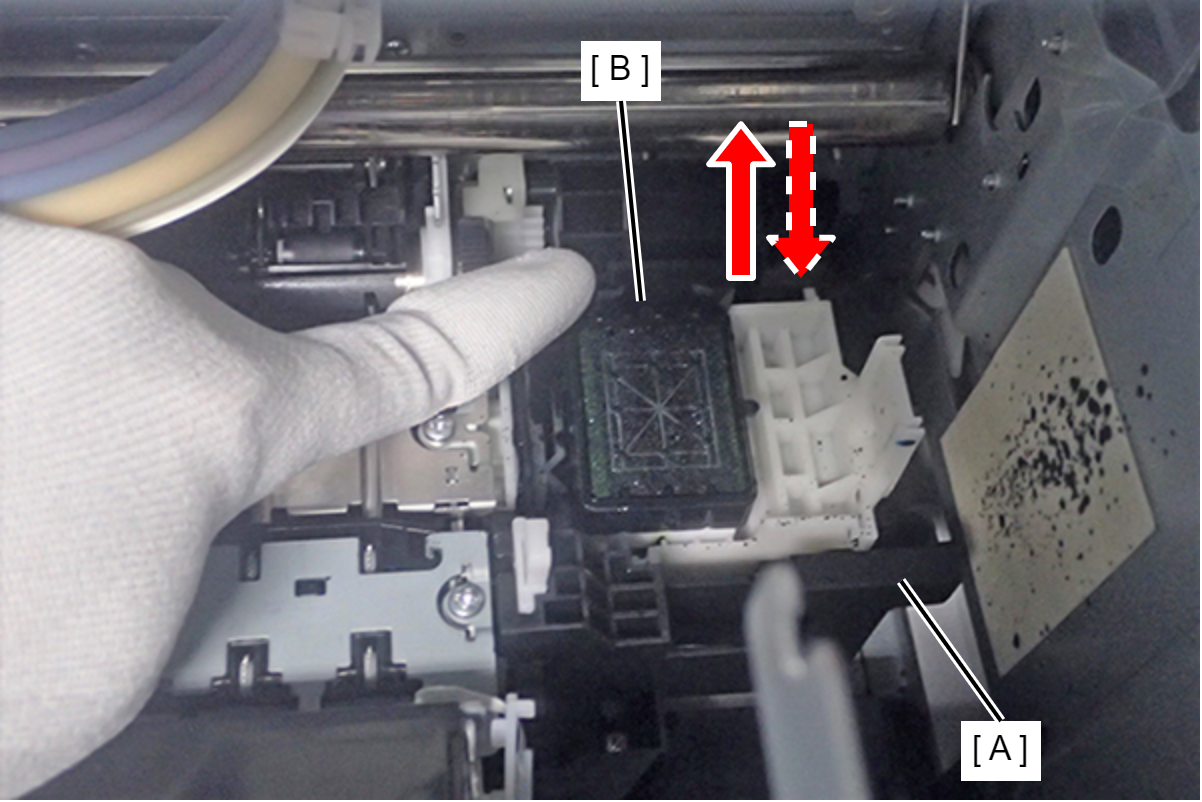
In this printer, the cap of the ink system follows the inclination of the Print Head. However, if hardened ink is accumulated on the cap, capping may not be done properly and printing failure may result. After the adjustment is complete, make sure to perform the operation check of the cap following the procedure below.
- Push the cap of the ink system (A) to the rear and confirm the cap (B) surely returns to the original position.
- Push the cap of the Cap Unit to the home position and confirm the cap surely returns to the original position.
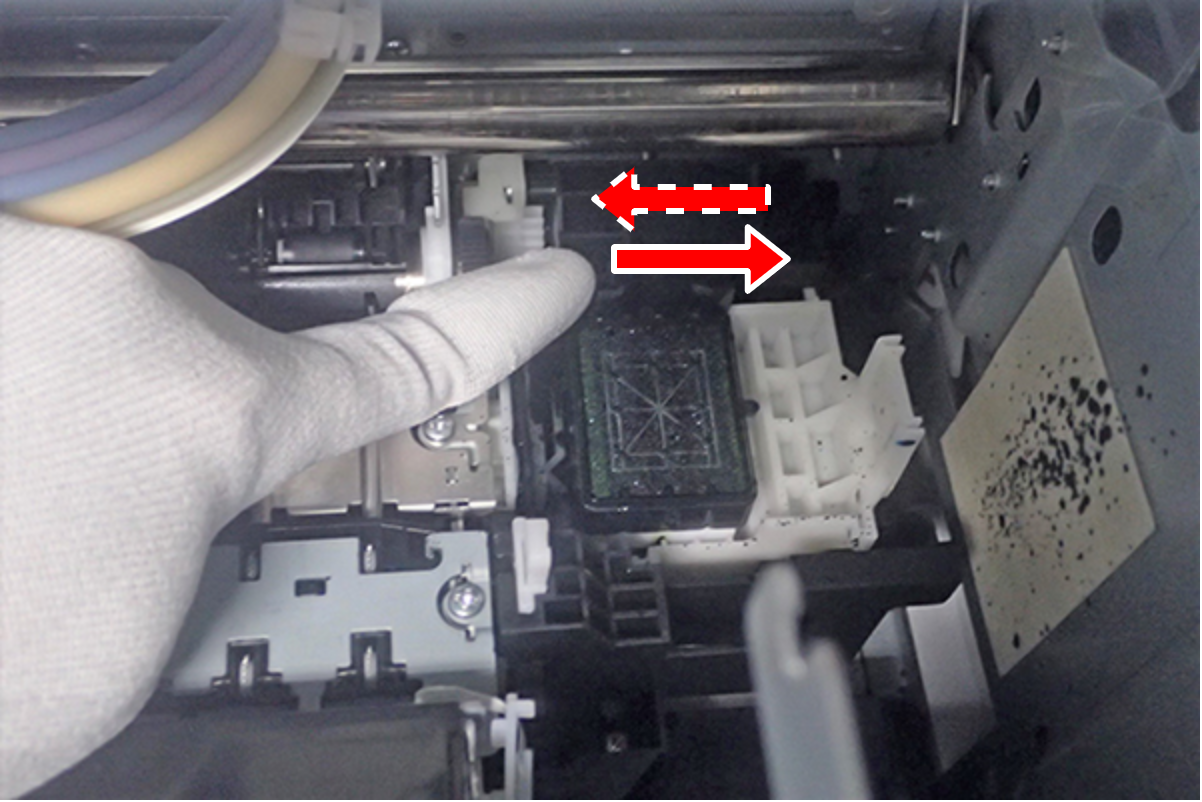
Repeat Step 1 to Step 2 a few times. If the action of the cap is too slow or awkward, or does not return to the original position, replace the ink system with a new one.
Assembly / 組み立てPreparation before Adjustment
- Wrap the front cover open sensor (A) with tape and disable the sensor function.
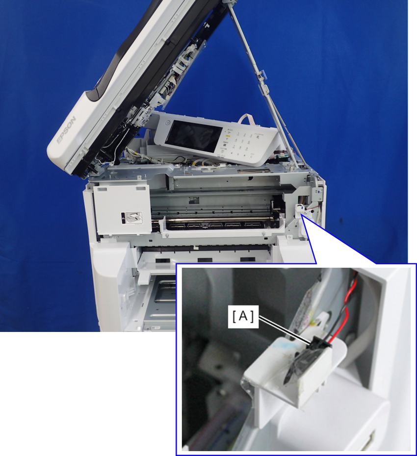
Install the ink pack and the Maintenance Box.
Caution / 注意Wrap the front cover sensor (A) with tape surely. (When the adhesive tape peels off, the CR unit unintentionally moving.)
- Connect the four Head FFCs (B) to the connector of the Print Head (A).
| Adjustment / 調整 |
After replacing this part, you need to run the menu from the service support mode. (If you ran the Before-replacement menu before replacing the part, it will start automatically when you turn the power on.) |