
Regular Maintenance Procedures
Perform the periodic maintenance operation according to the following procedure.
- Start the service support mode. (Starting Service Support Mode)
- Select "04 Maintenance" from the service support mode menu.
- Select “410 Regular Maintenance”.
- Select”41001 Before performed”.
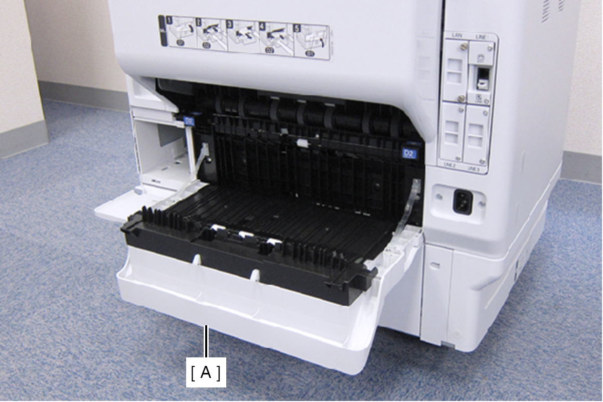
- Open the Duplex Print Cover (A).
- Remove the two screws, then remove the Connector Cover (A).
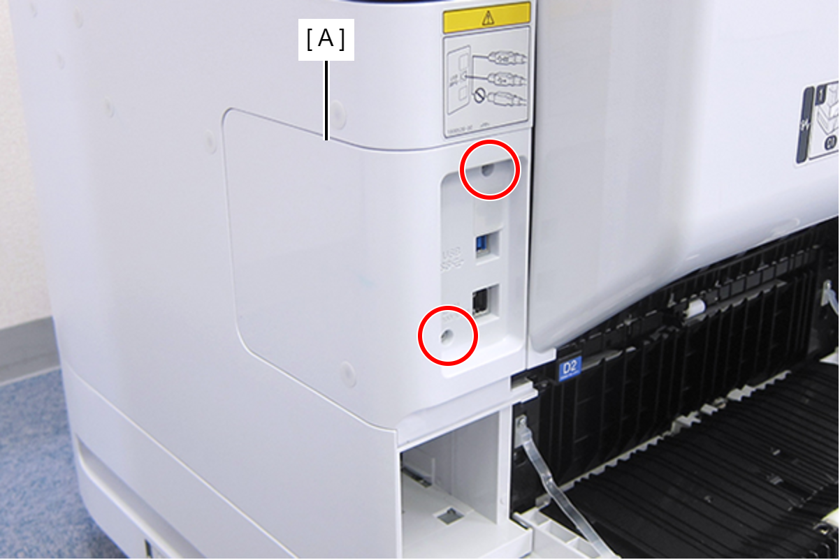
 : C.B.S-TITE-SCREW-3x8-F.ZN-3C
- Remove the two screws, then remove the Right Housing Assy (A) toward the rear of the product.
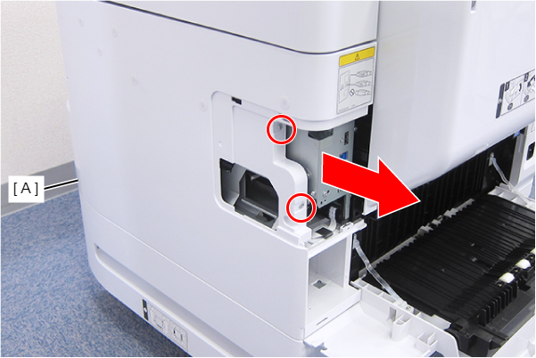
- : C.B.S-TITE-SCREW-3x8-F.ZN-3C
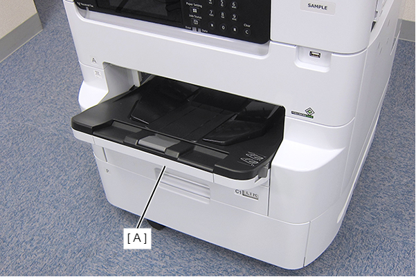
- Remove the Stacker Assy (A).
- Remove the Cassette Assy (A).
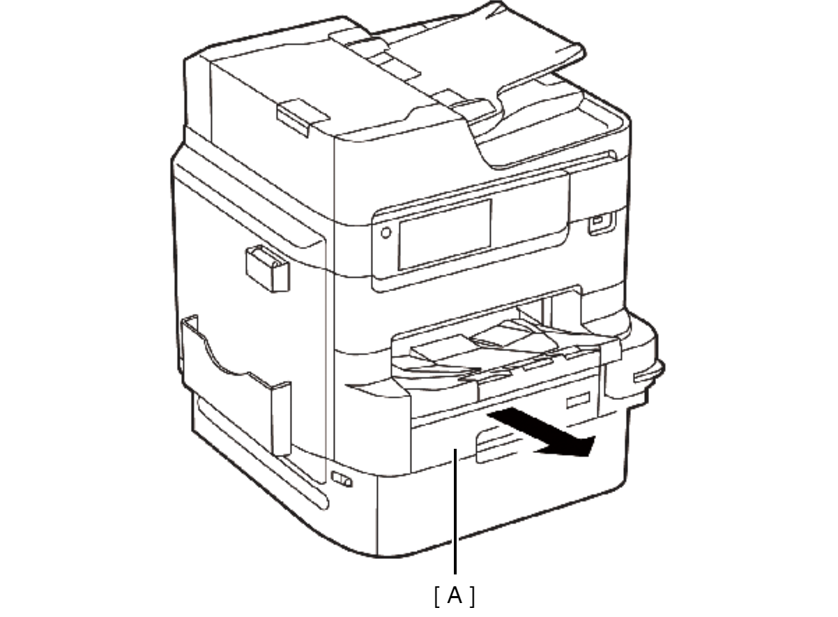
- Open the Front Cover Assy (A).
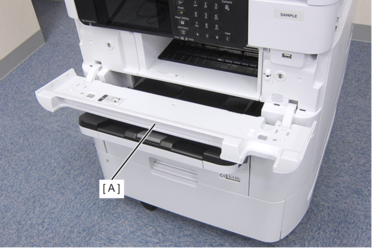
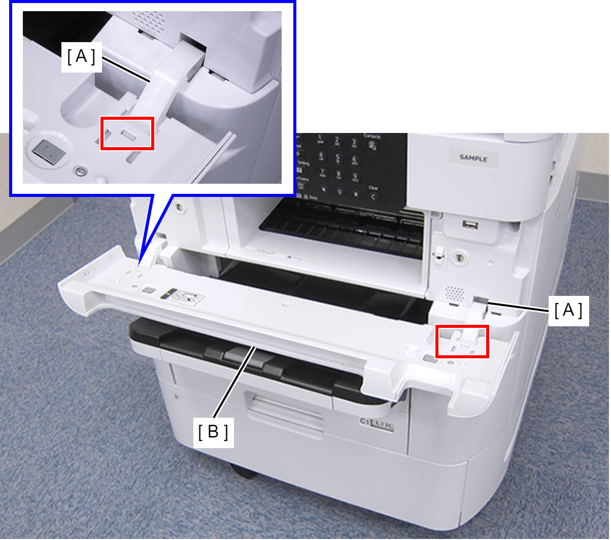
- While pressing the two hooks of the hinge (A), remove the Front Cover Assy (A) frontward.
- Remove the three screws that secures the Front Right Housing (A).
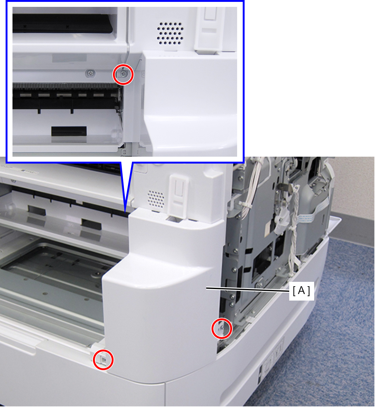
- : C.B.S-TITE-SCREW-3x8-F.ZN-3C
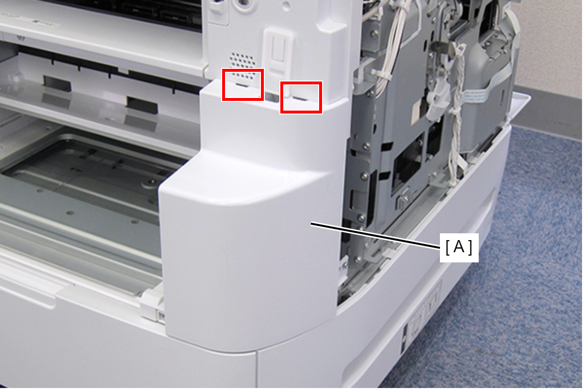
- Disengage the two hooks, and remove the Front Right Housing (A).
- Remove the four screws, then remove the Front Middle Frame (A).
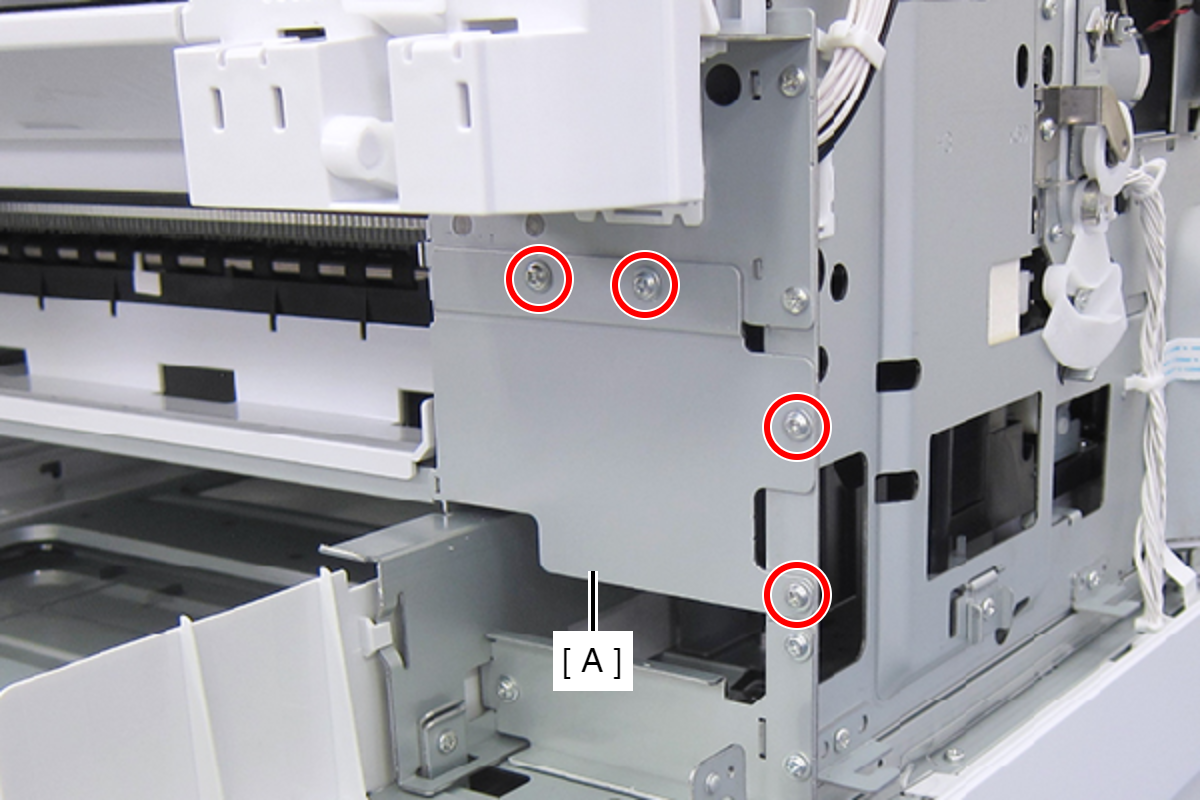
- : C.C.S-TITE-SCREW-3x5-F.ZN-3C
- Remove the screw, then remove the IS Holder Plate (A) in the direction of the arrow.
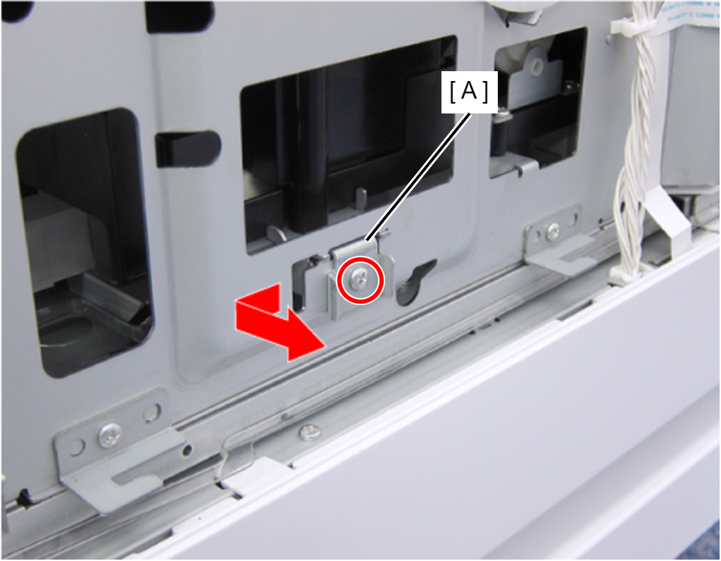
 : C.B.S-TITE-SCREW-3x8-F.ZN-3C
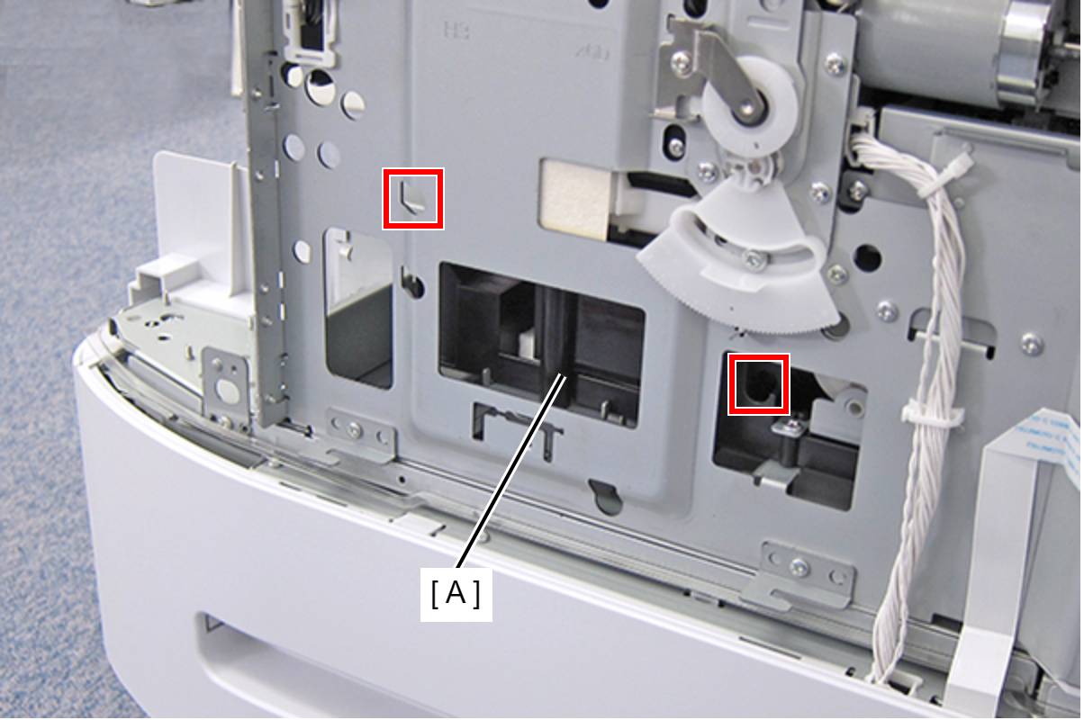
- Insert the screwdriver into the hole and turn each of the two screws that secure the Ink System Assy (A) until you feel the screw is spinning free.
 Check Point / チェックポイント
- Release the CR lock, then move the CR Unit to center before removing the Ink System Assy.
- Because the screws are captive screws, they do not come off.
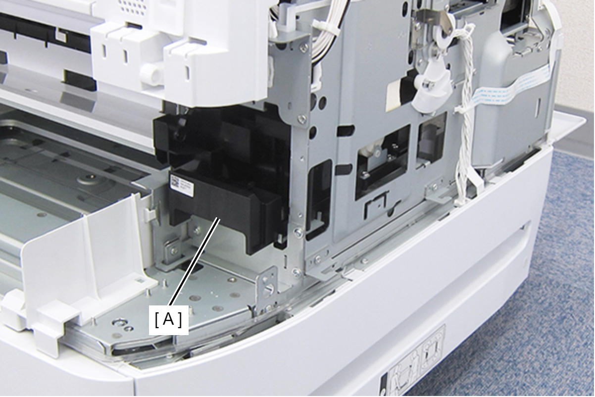
- Remove the Ink System Assy frontward (A).
 Check Point / チェックポイント
- Do not touch the to-be-capped section (A) of the Ink System Assy.
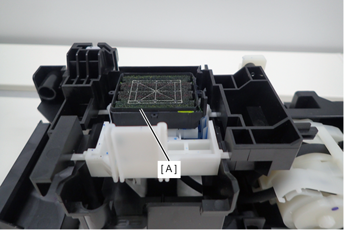
- Make sure the to-be-capped section is level. If the section is tilted, the rib (A) on the back is trapped. Release the rib and make sure the to-be-capped section is level.
- If the printer is used with the to-be-capped section tilted, the Print head will not be capped correctly, causing the ink nozzles to clog.
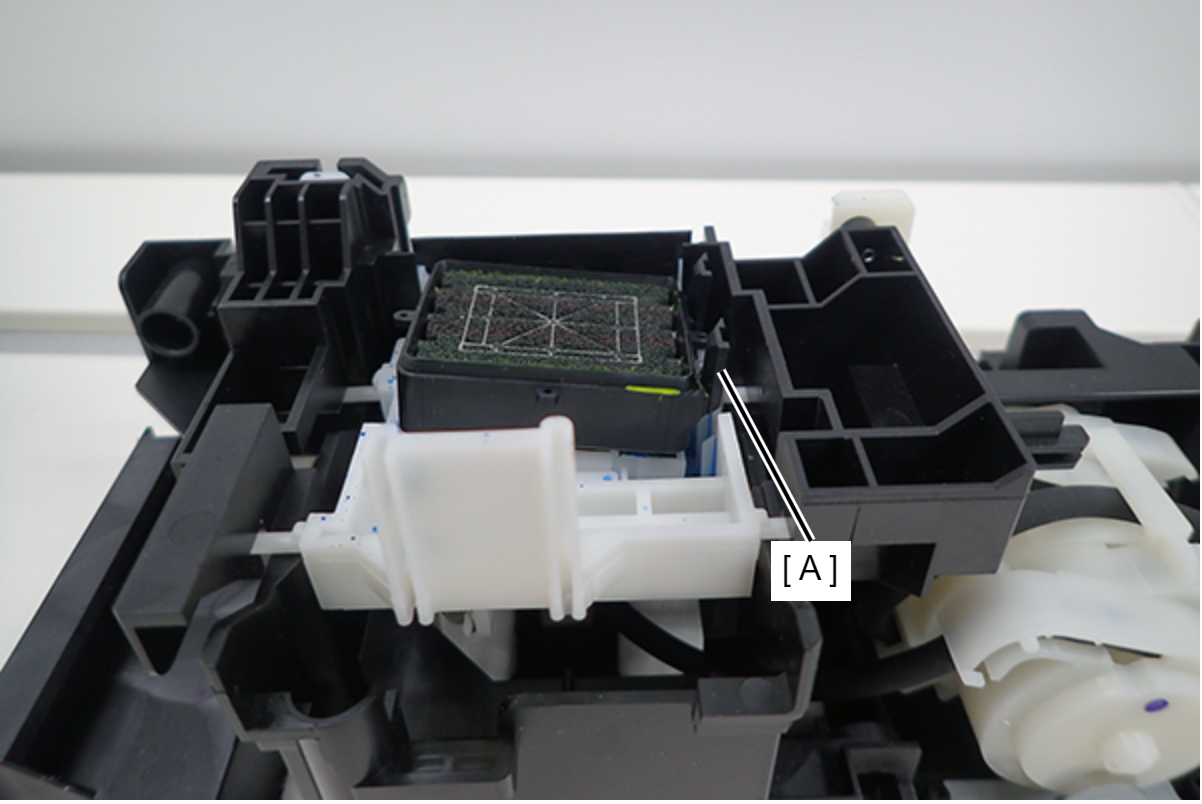
- If the printer is used with the to-be-capped section tilted, the Print head will not be capped correctly, causing the ink nozzles to clog.
- Do not touch the to-be-capped section (A) of the Ink System Assy.
- Remove the three screws, then remove the Left Housing Assy (A) toward the rear of the product.
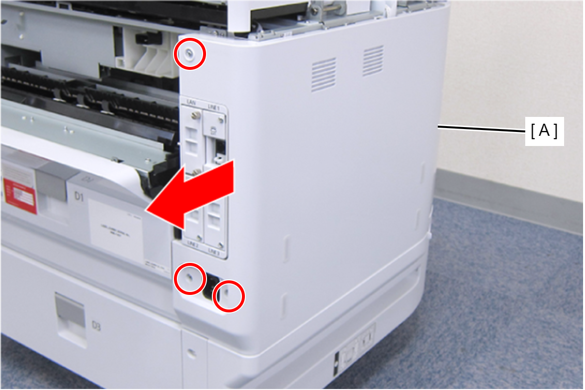
- : C.B.S-TITE-SCREW-3x8-F.ZN-3C
- Remove the hole from the screw feet (A) and pull out the folded portion (C) of the PF Scale Protection Material (B).
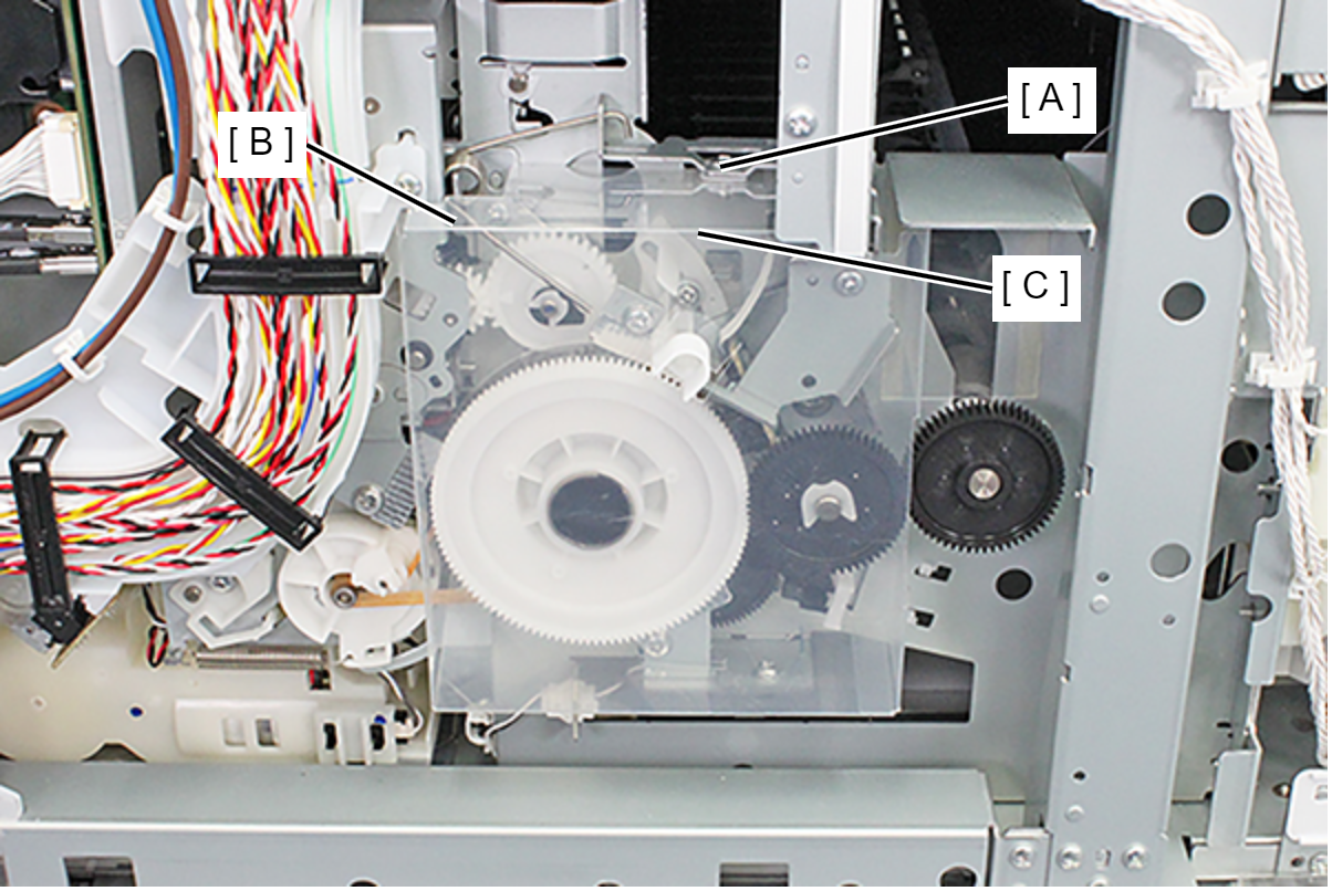
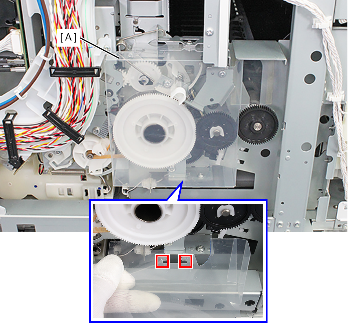
- Release the two hooks and remove the PF Scale Protection Material (A).
- Remove the screw, then remove the Left PG Cam Screw Holder (A) with the screw.
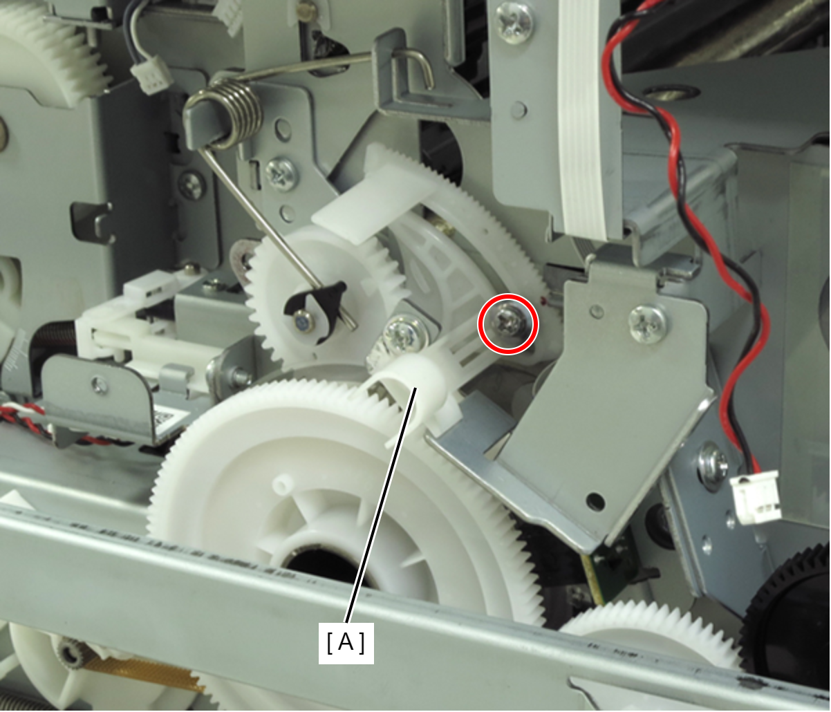
- : C.C.SCREW-3x6-F.ZN-3C
- Remove the screw, then remove the Anti Static Brush Plate (A).
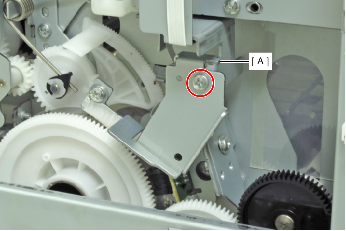
- : C.B.S-TITE-SCREW-3x6-F.ZN-3C
- Soak the Polyester Swab (A) with alcohol (Ethanol).
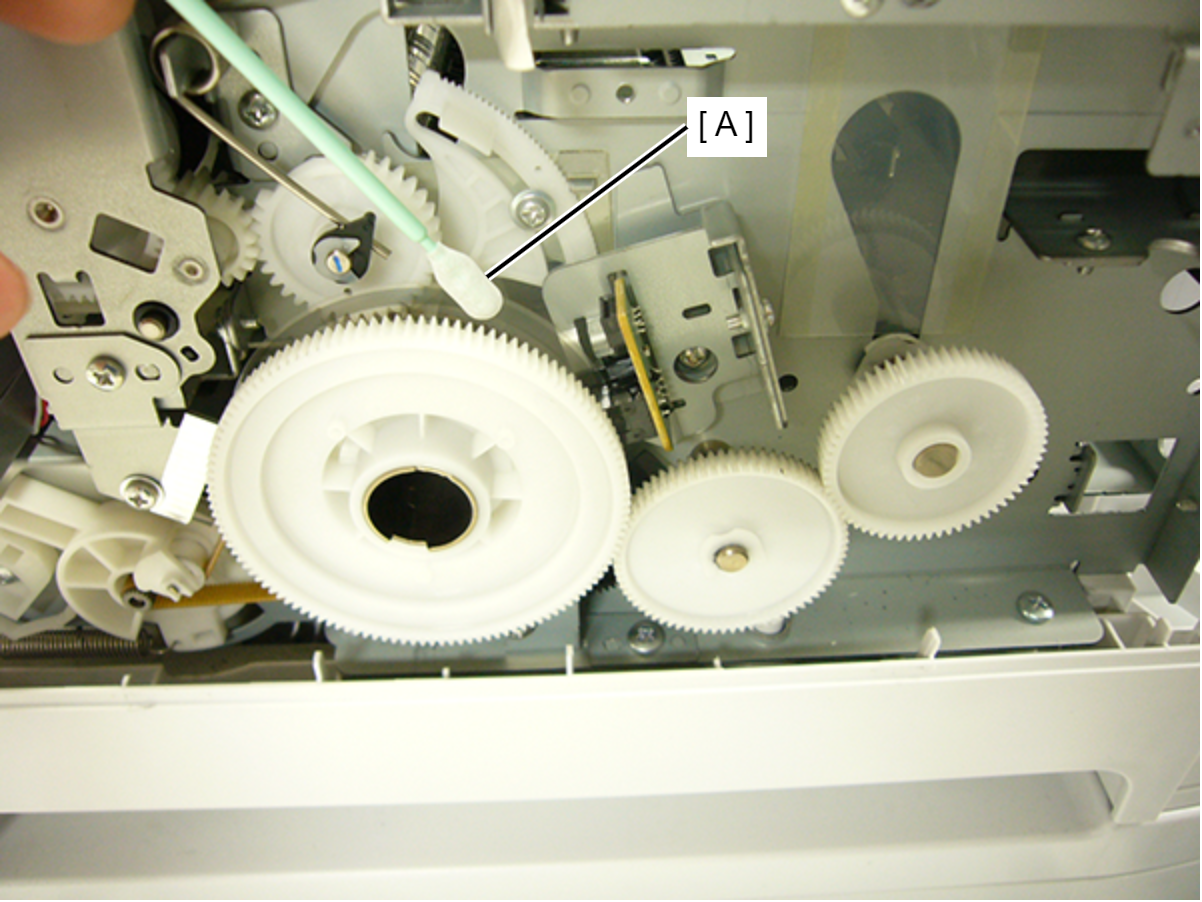
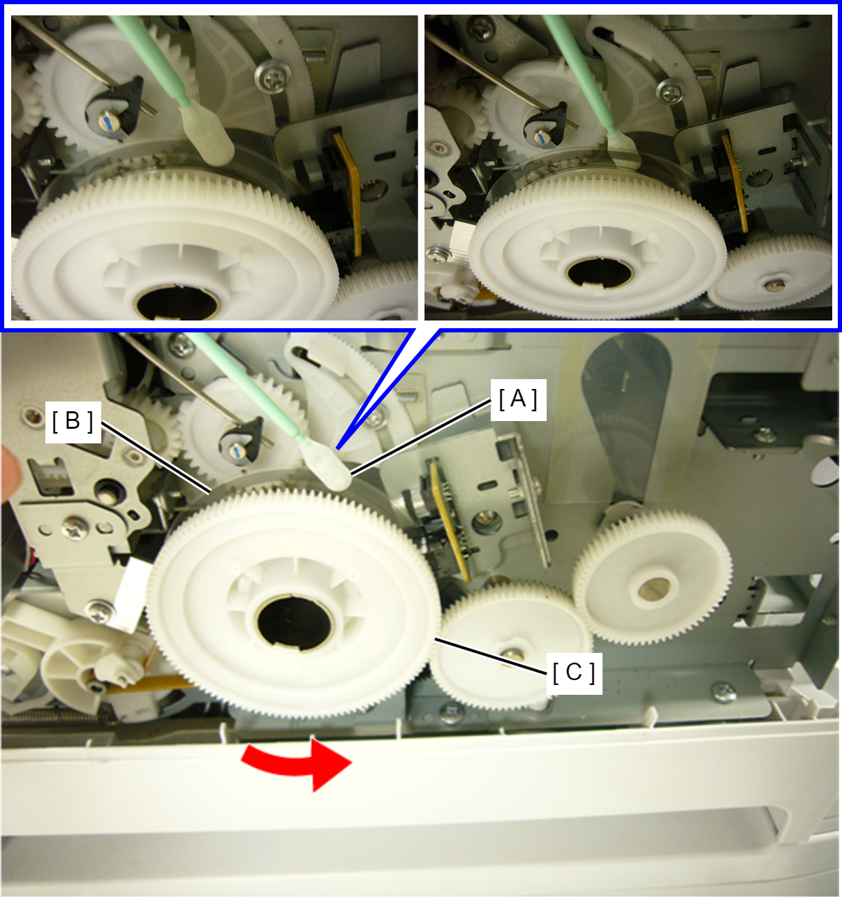
- Rotate the PF Gear (C) counterclockwise by hand and clean the scaled part on the PF Scale (B) with the Polyester Swab (A). (Clean both the front and back surfaces.)
 Caution / 注意
- Make sure not to add strong force to PF Scale.
- Clean the PF Scale until contamination does not adhere to the Polyester Swab.
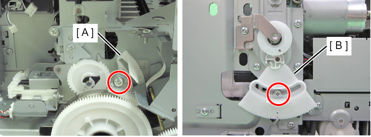
- Remove the screws of Left PG Cam (A) and Right PG Cam (B).
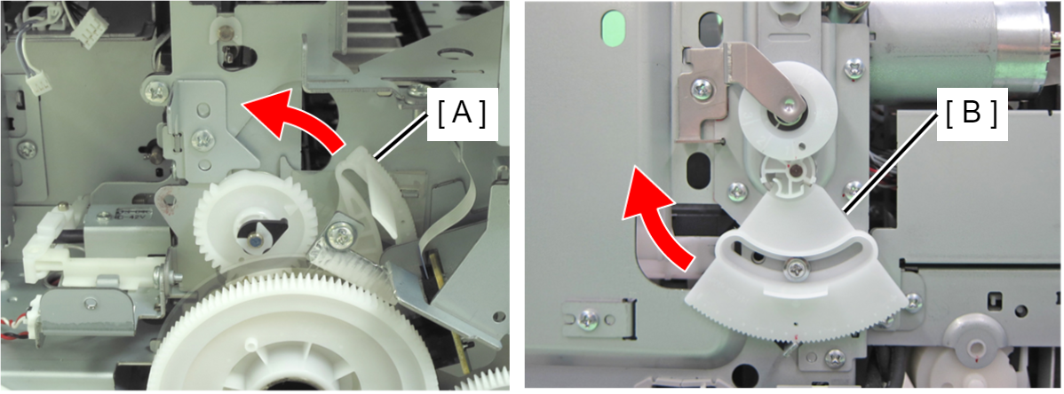
- Move the each PG Cam (A/B) one notch in the direction in which PG increases.
- Remove the four screws, then remove the Front Inner Housing Center (A) frontward.
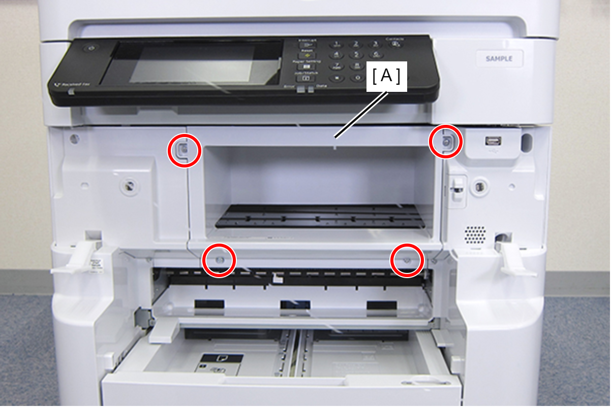
- : C.B.S-TITE-SCREW-3x8-F.ZN-3C
- Remove the three screws fastening the Front Left Housing (A).
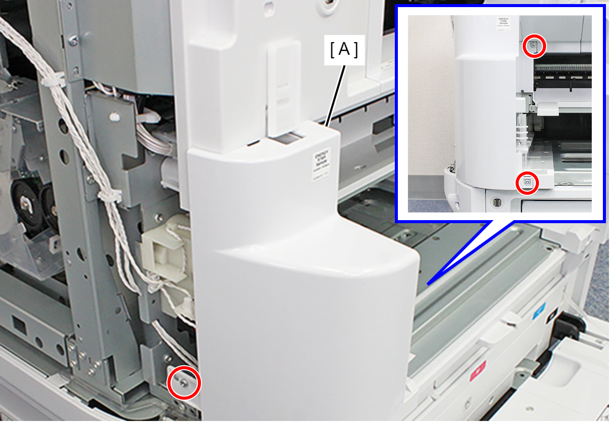
- : C.B.S-TITE-SCREW-3x8-F.ZN-3C
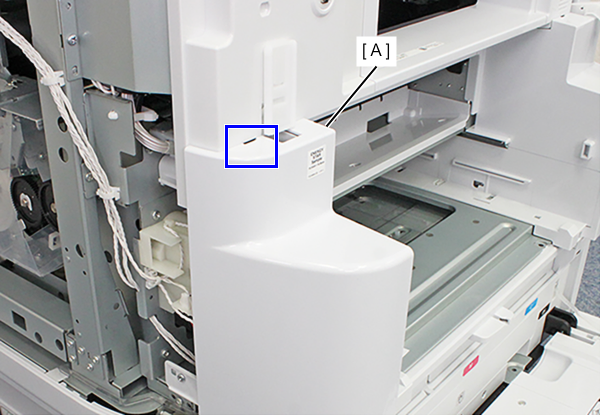
- Release the hook and remove the Front Left Housing (A).
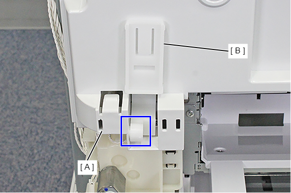
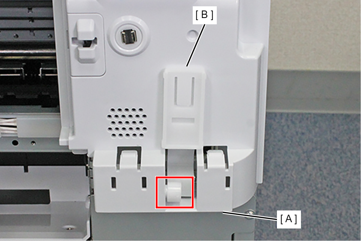
- Remove the Front Cover Hinge Left (B) from the Dowel on the Front Inner Housing Left (A).
- Open the ADF Unit.
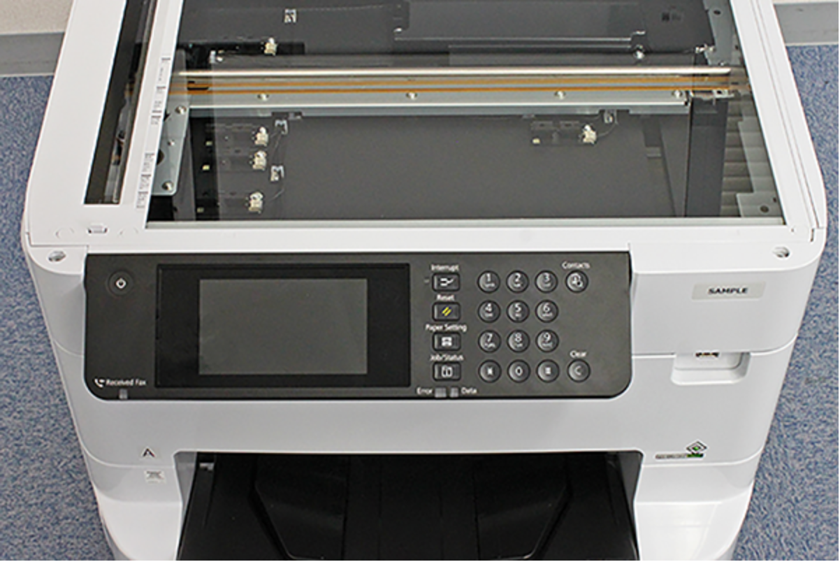
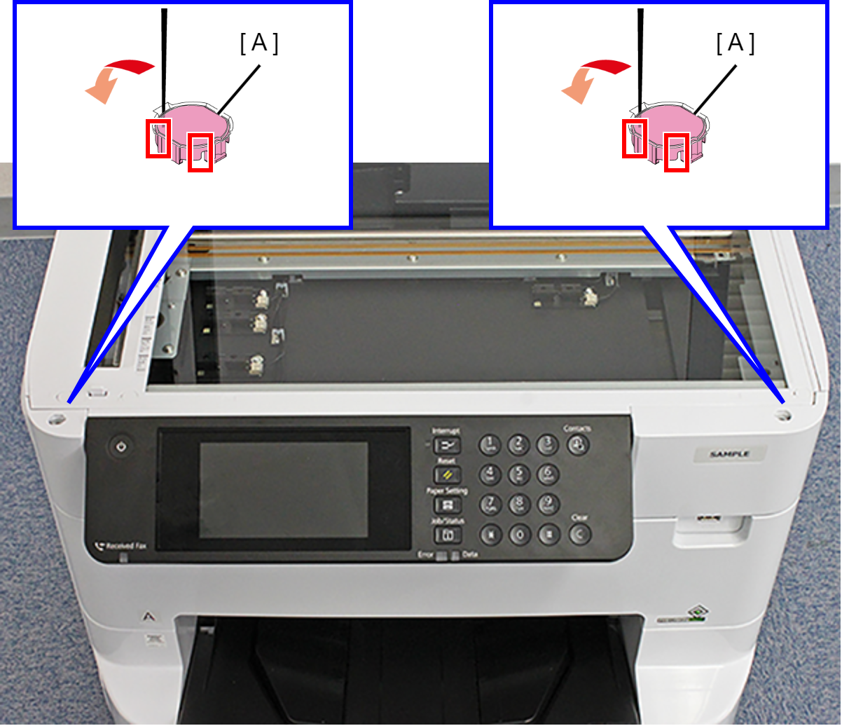
- Release the hook by inserting a narrow-tipped object, such as tweezers or the like, as shown above, and remove the two SCN Housing Caps (A).
- Remove the two screws.
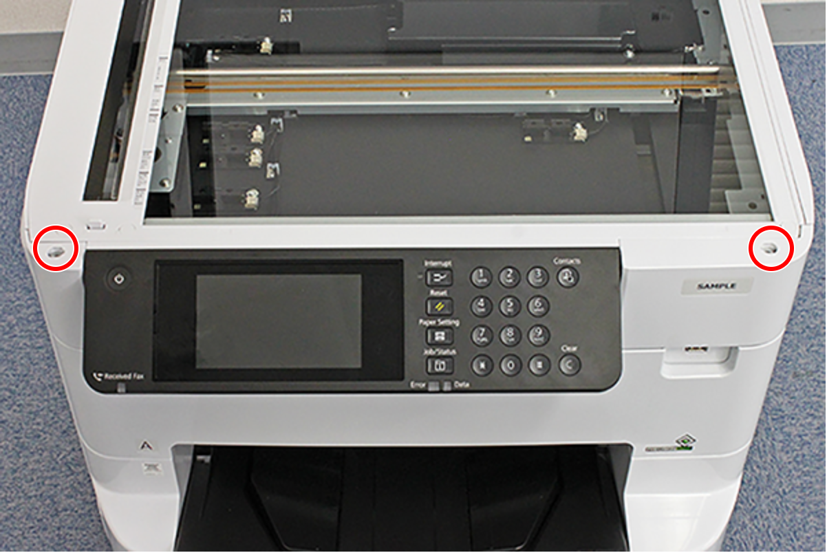
- : C.B.S-TITE-SCREW-3x8-F.ZN-3C
- Open the Panel Unit (A).
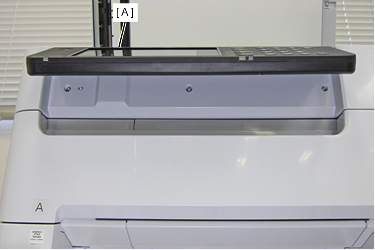
- Remove the three screws.
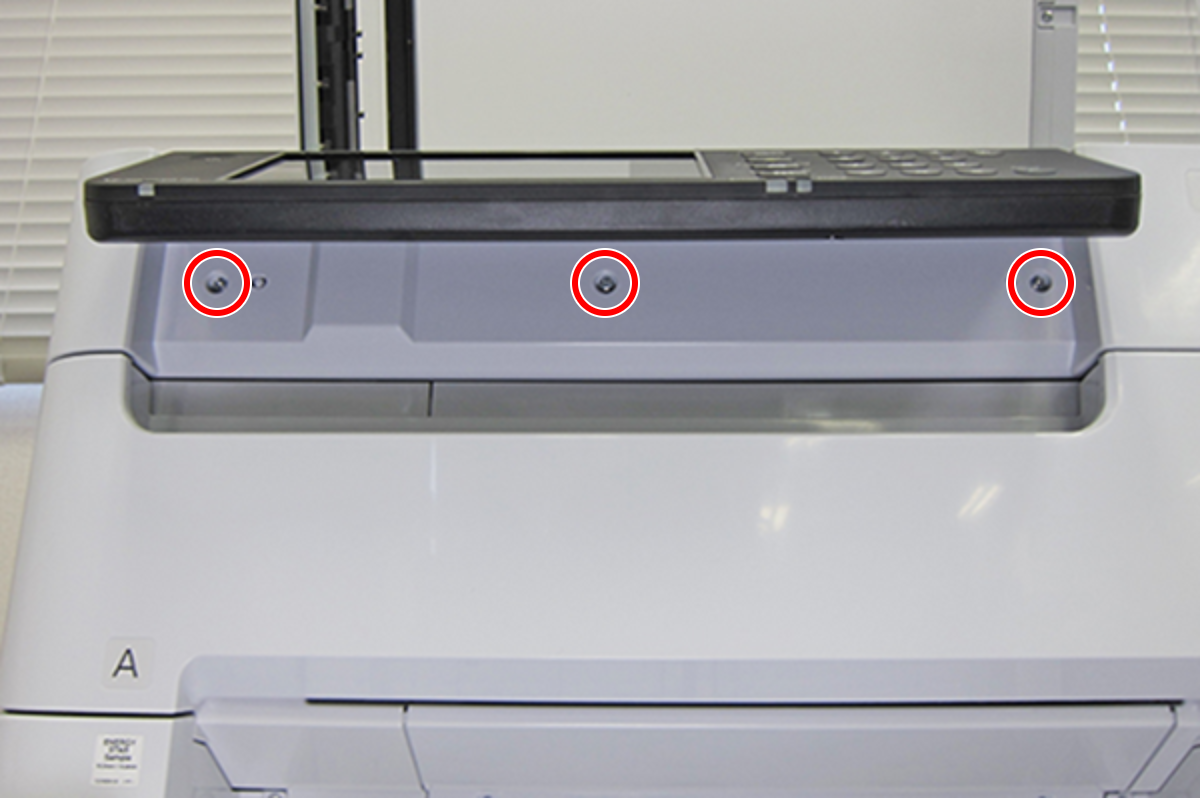
- : C.B.S-TITE-SCREW-3x8-F.ZN-3C
Check Point / チェックポイント- The three screws fastening the Front SC Cover are mounted facing downward, so it is possible to remove the screws from below the Panel Unit.
- Open the Front Cover Assy (A).
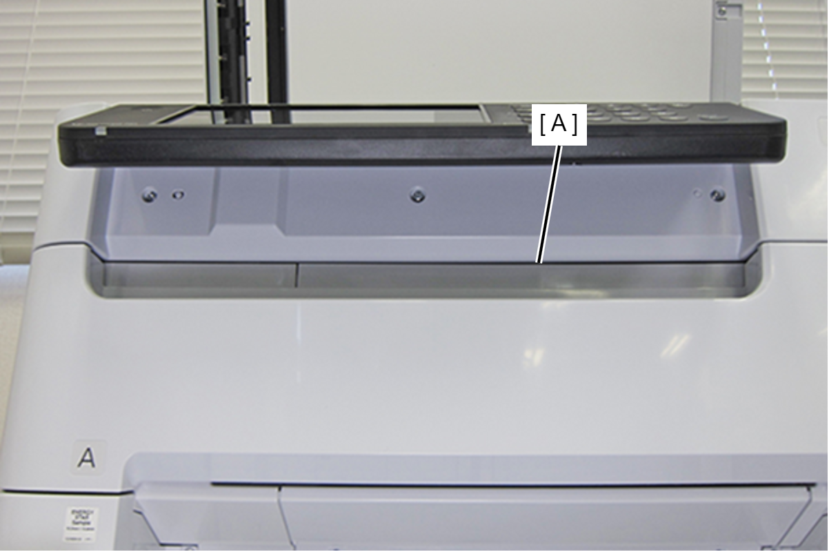
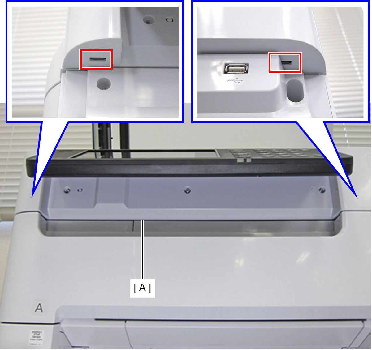
- Release the two hooks and remove the Front SC Cover (A).
- Remove the two screws fastening the Front Inner Housing Left (A).
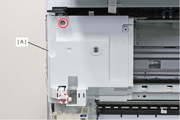
- : C.B.S-TITE-SCREW-3x8-F.ZN-3C
- Remove the Front Inner Housing Left (C) while releasing the place interfering (A) with the ADF/SCN Unit (A).
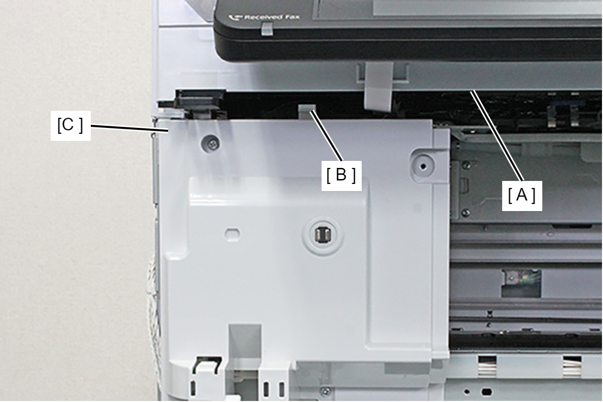
- Remove the two screws.
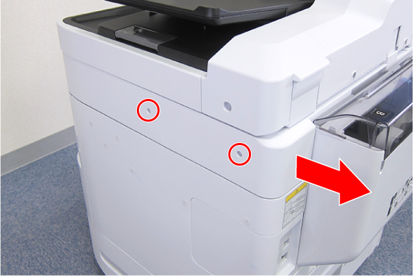
- : C.B.S-TITE-SCREW-3x8-F.ZN-3C
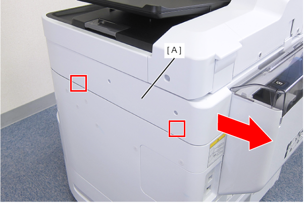
- Disengage the two hooks by sliding the Right SC Cover (A) toward the rear of the product, then remove it.
- Remove the screw.
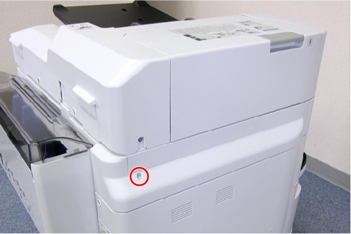
- : C.B.S-TITE-SCREW-3x8-F.ZN-3C
- Slide the Left SC Cover (A) toward the rear of the product to disengage the tab.
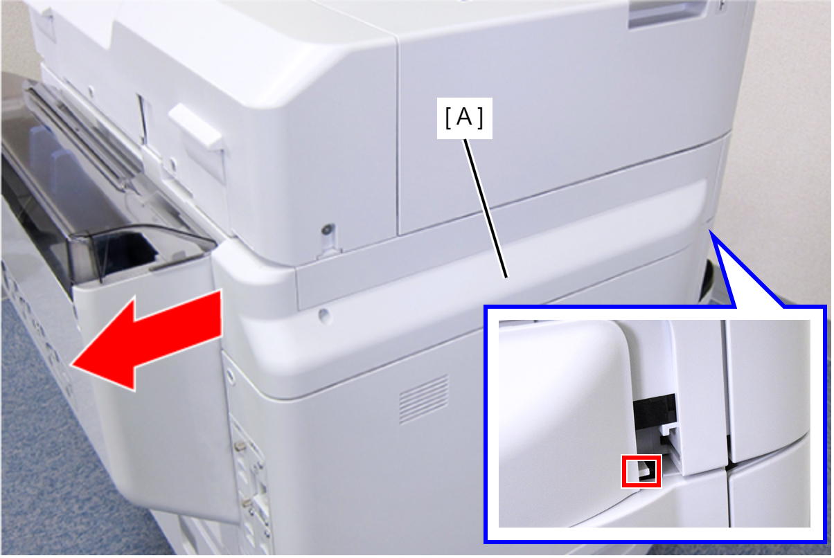
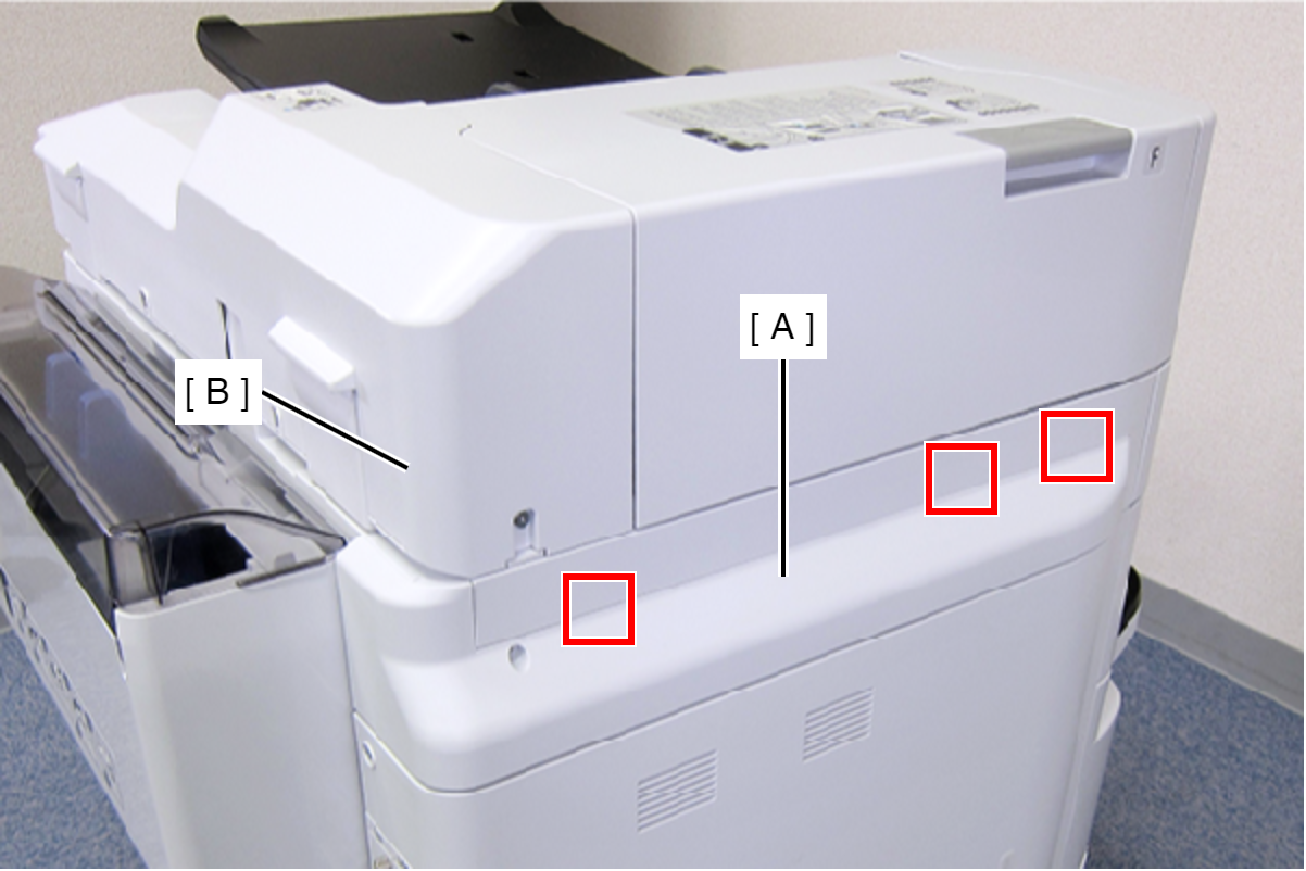
- Disengage the three tabs by inserting a flathead screwdriver into the gap between the Left SC Cover (A) and the ADF Unit (B), and then remove the Left SC Cover (A).
- Remove the two screws.
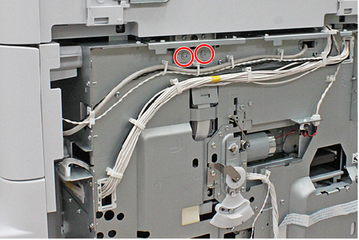
- : C.C.S-TITE-3x6-F.ZN-3C
- Raise the ADF Stopper (A) to lock the ADF Unit.
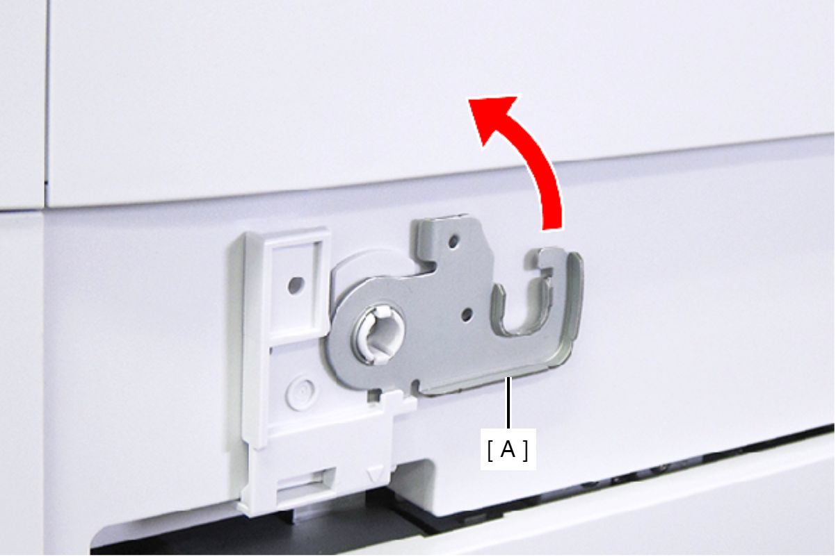
- Secure the ADF Stopper with one of the screws you removed at step 1.
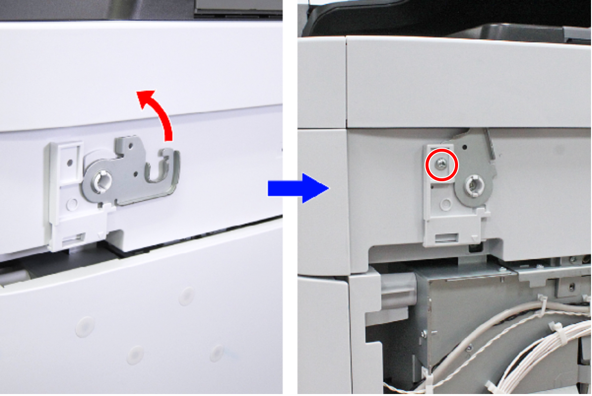
- : C.C.S-TITE-3x6-F.ZN-3C
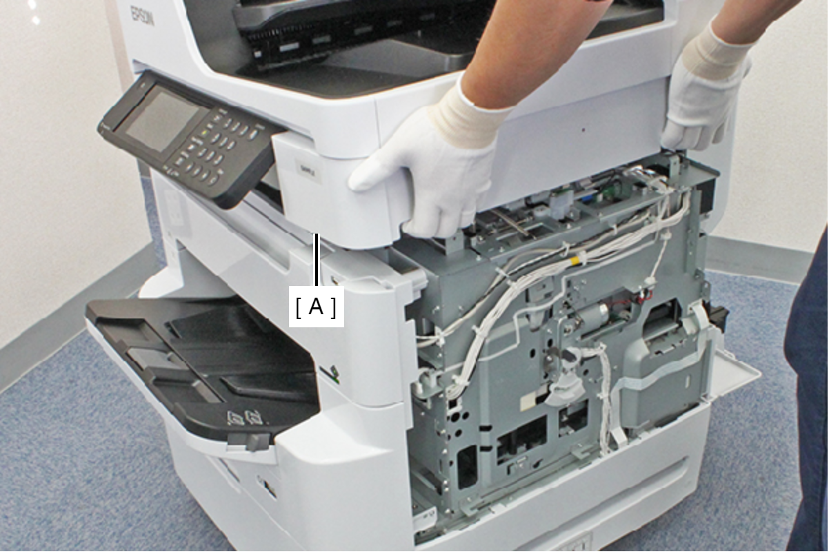
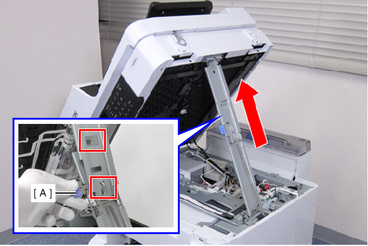
- Hold the ADF/SCN Unit (A) with both hands as shown above, and open the ADF/SCN Unit (A).
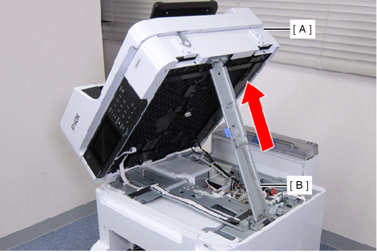
- Open the ADF/SCN Unit (A) and extend the support stand (B) as far as it goes, then support theADF/SCN Unit (A) with the support stand.
 Caution / 注意
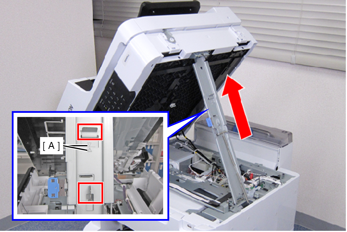
Make sure that the extended support stand is fixed with the two hooks, and the two triangle marks face to each other.
 Check Point / チェックポイント
When closing the ADF/SCN Unit, hold down the switch on the support stand and raise the ADF/SCN Unit in the direction of the arrow to disengage the two hooks, then fold the support stand.
- Remove the Front Cover Hinge Right (B) from the Dowel on the Front Inner Housing Right (A).
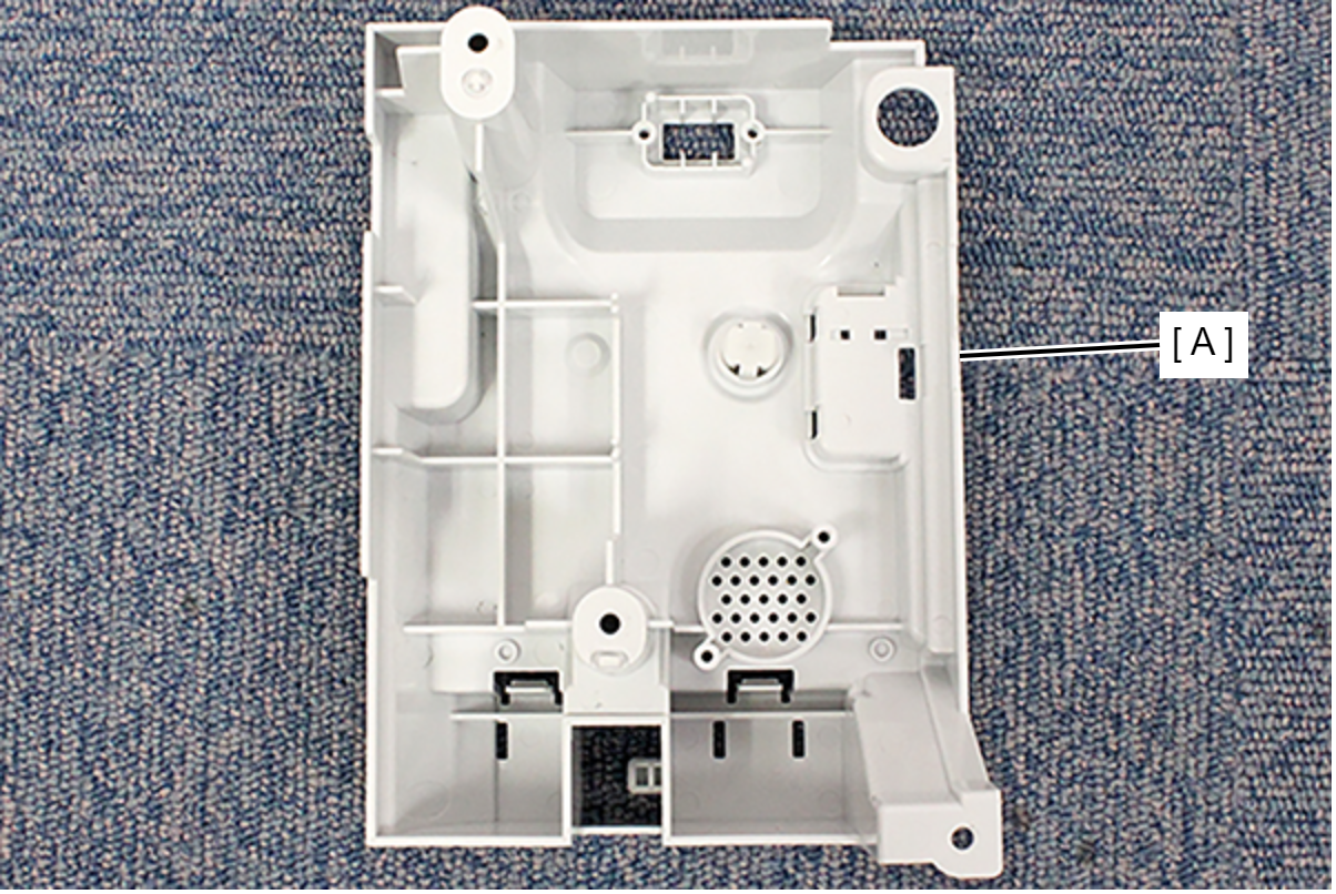
- Remove the Front Inner Housing Right (A).
- Move the CR Unit (A) to the center of the product to make it possible to access the Driven Rollers (D) on the Paper Guide Upper Left (B) and the Paper Guide Upper Right (C).
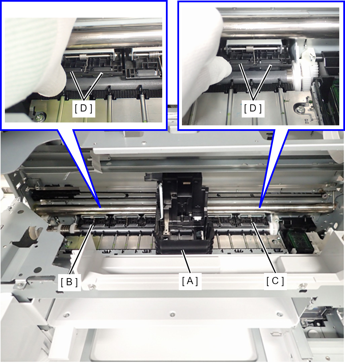
- Hold up the Paper Guide Upper Left (A) or Paper Guide Upper Right (B) by finger, and push the edge of Driven Roller (C) (two position). Remove the Driven Roller (C).
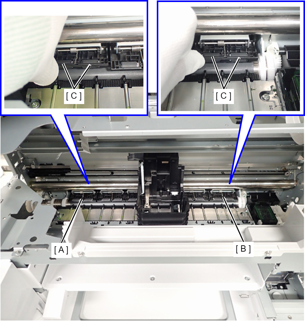 Caution / 注意
When removing the driven roller, make sure the shaft of the driven roller does not fall inside the product.
Also, confirm the check points on the next page before removing the driven roller.
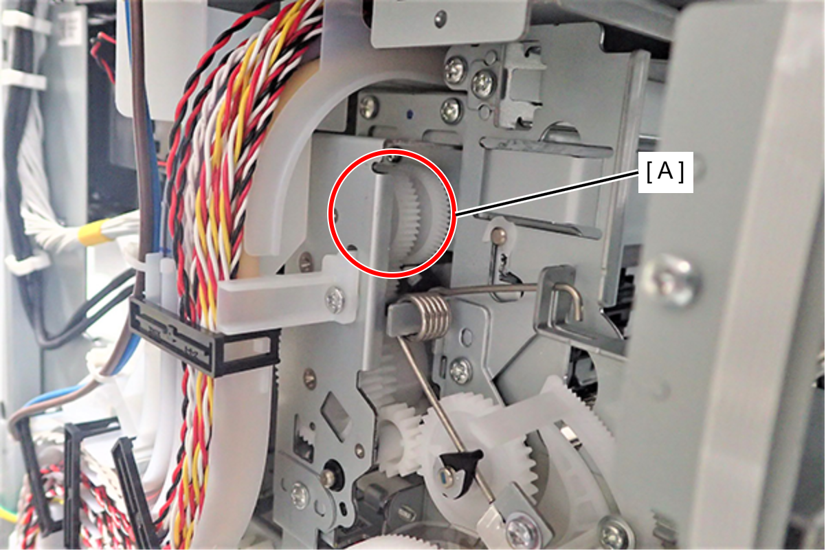
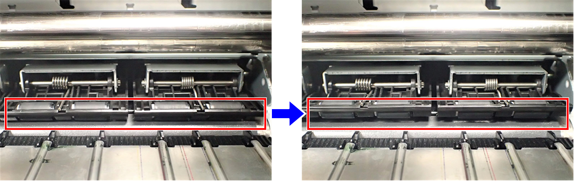
Check Point / チェックポイントBy rotating (clockwise) the gear (A) on the left side of the product, the angle of the paper guide becomes larger and the driven roller can be easily replaced.
 Assembly / 組み立て
- Put the Driven Roller (A) aligned in the Paper Guide Front.
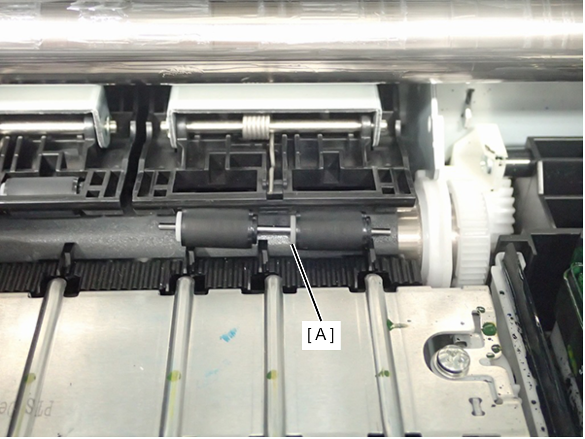
Hold up the Paper Guide Upper Left or Paper Guide Upper Right (A), and move the Driven Roller (B) to installing position.
- Push the edge (C) of Driven Roller (two position), and install the Driven Roller (B).
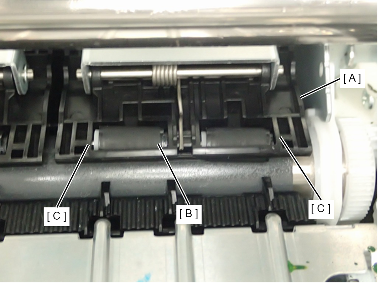
Caution / 注意Driven Roller has installation direction. Therefore, make sure to install the Drive Roller correct direction. (The white part of Drive Roller faces the center)
- Put the Driven Roller (A) aligned in the Paper Guide Front.
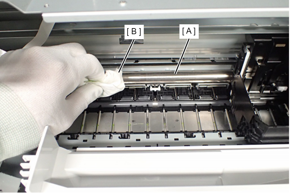
- Wipe off the lubricant on the CR Shaft (A) using a dust-free cloth (B).
 Check Point / チェックポイント
Make sure to wipe off the back side of the CR Shaft as well.
The CR Shaft can be rotated by turning the gear of the APG Drive Assy (A) by hand.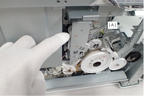
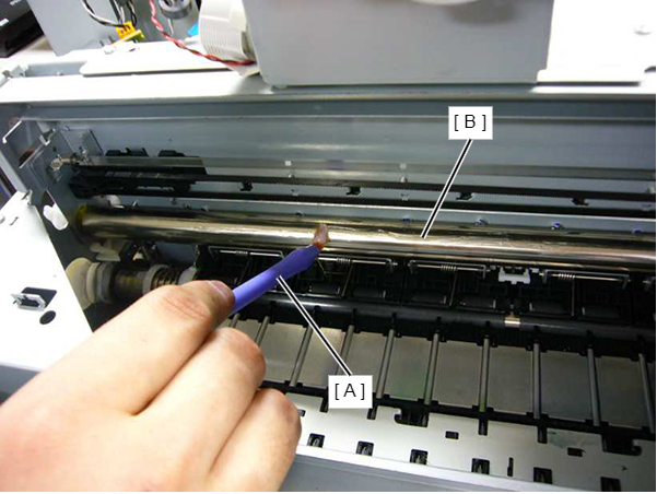
- Move the CR Unit (A) to the home position side (right side of the printer).
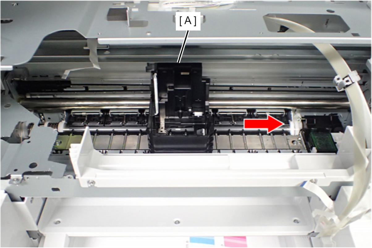
- Lubricate the CR Shaft (B) with a brush (A).
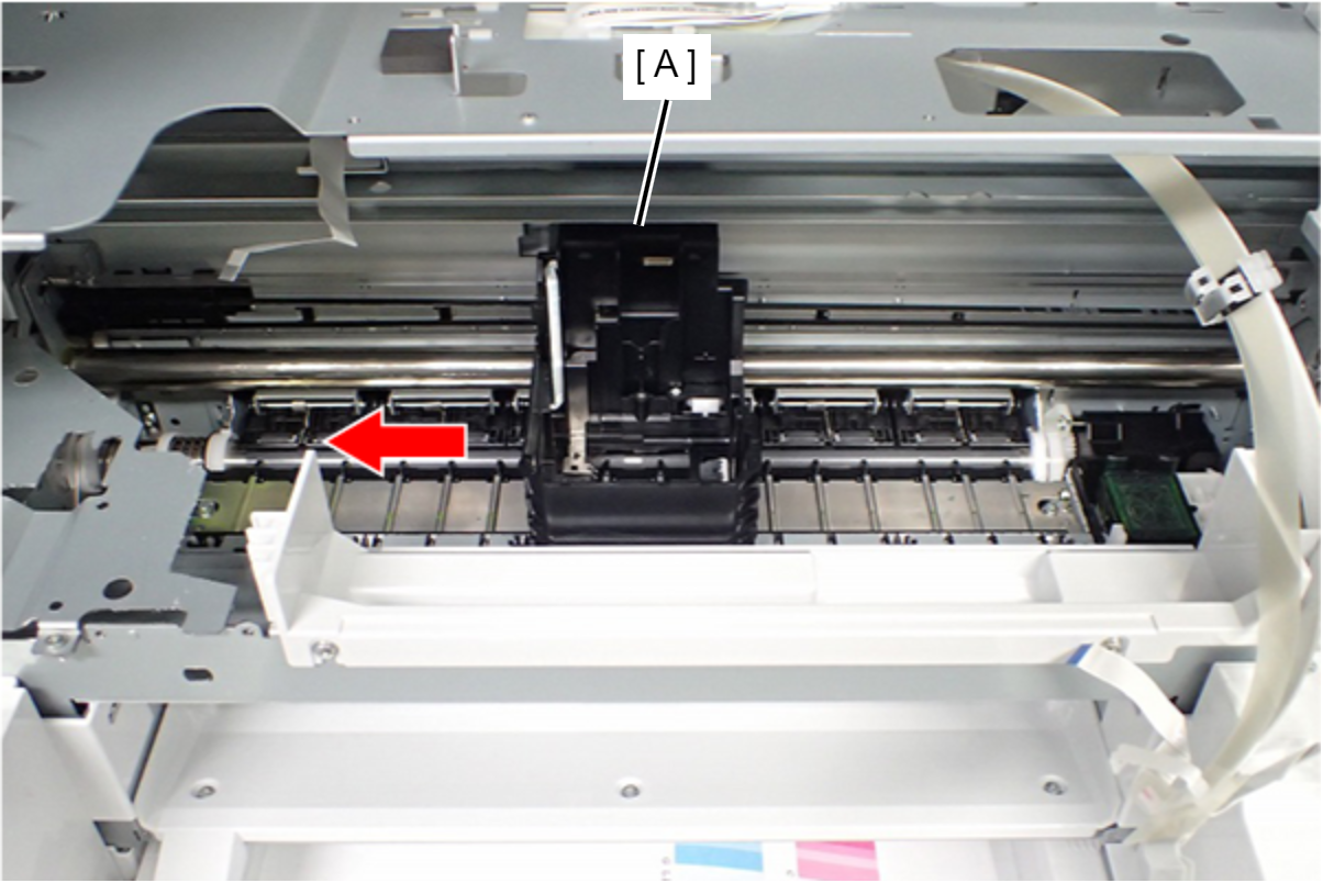
- Move the CR Unit (A) to the Full side (left side of the printer) and lubricate the CR Shaft.
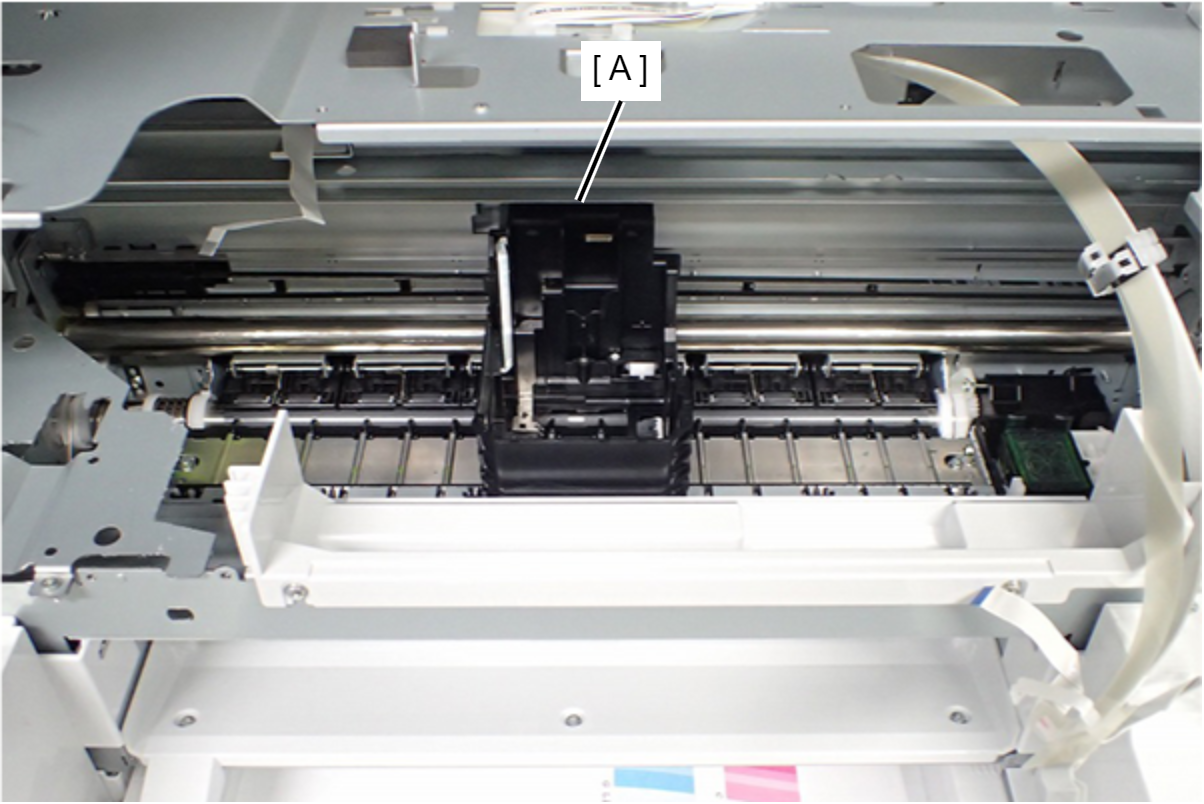
- Rotate the gear of the APG Drive Assy (A), and make the back side of the CR Shaft visible.
- Lubricate the back surface of the CR Shaft in the same manner as above.
- Move the CR Unit (A) to the center of the printer.
- Lubricate one circumference of the shaft at two points on the CR Shaft.
Regarding the lubrication amount, refer to above figure.
- Full side (Left side of printer): Position (A) is between the Paper Guide Upper Left and the Paper Guide Upper Center.
- Home position side (Right side of printer): Position (B) is between the Paper Guide Upper Right and the Paper Guide Upper Center.
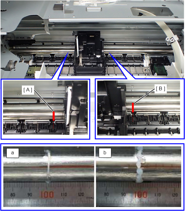
a: Minimum lubrication amount
b:Maximum lubrication amount
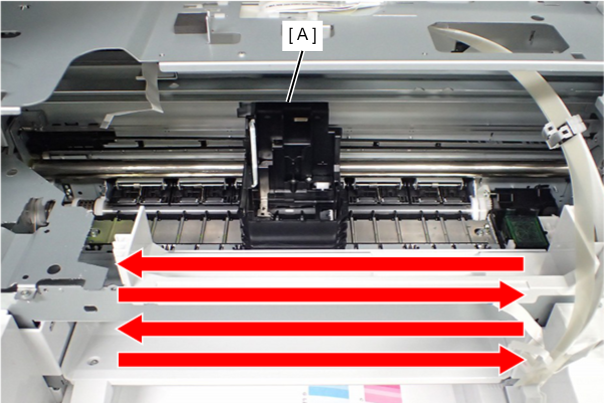
- Move the CR Unit (A) side to side twice to spread the lubricant.
- Check the bearing (B) of the CR Unit (A) and both ends (C) of the CR Shaft to ensure that there is no lubricant accumulation.
The photo in the callout box shows the maximum application amount.
If there is a lubricant accumulation, remove it using a cleaner stick or dust-free cloth.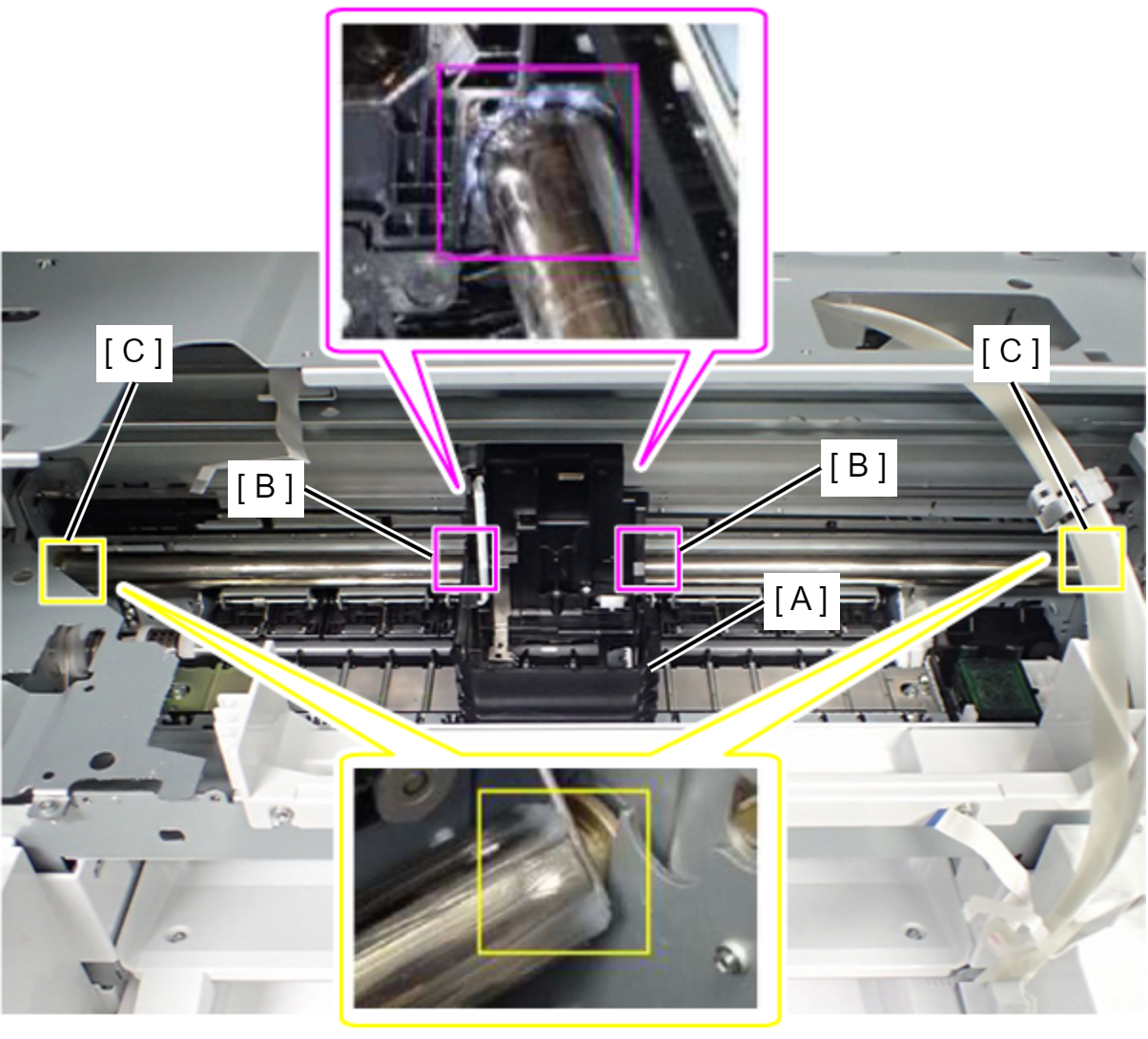
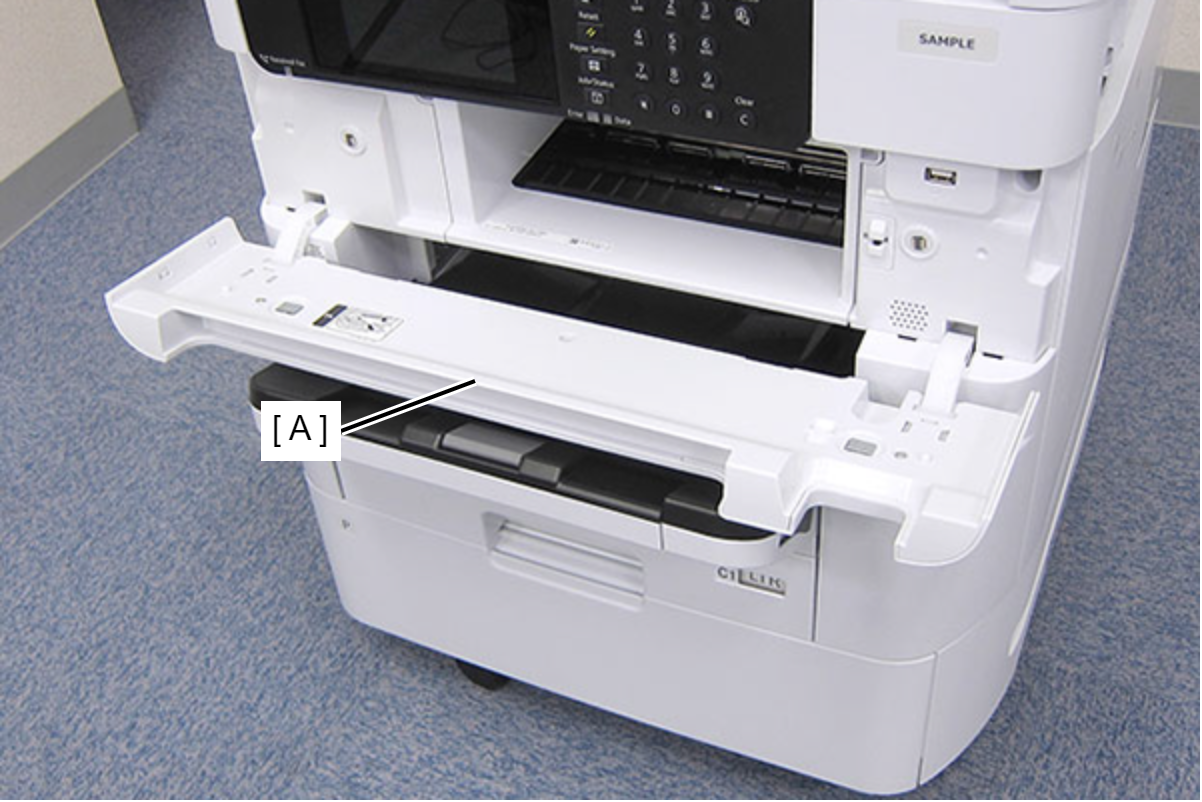
- Open the Front Cover (A).
- Clean the PE Sensor (A) with a cotton wool bud moistened with alcohol.
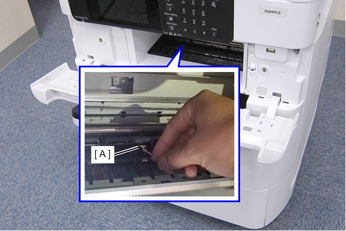 Check Point / チェックポイント
Clean the PE Sensor by wiping in the vertical angled direction as shown in the figure until ink no longer sticks to the cotton wool bud.
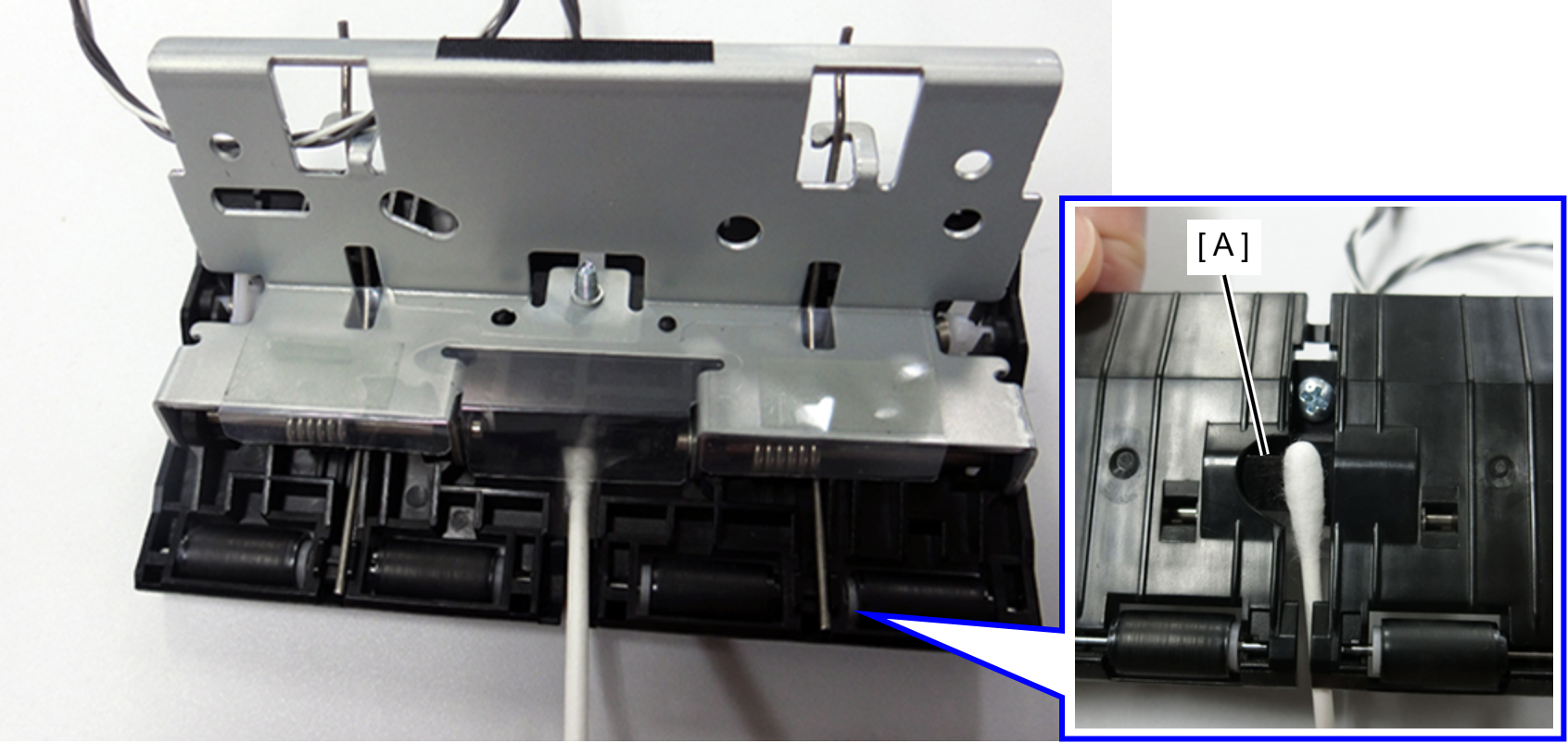
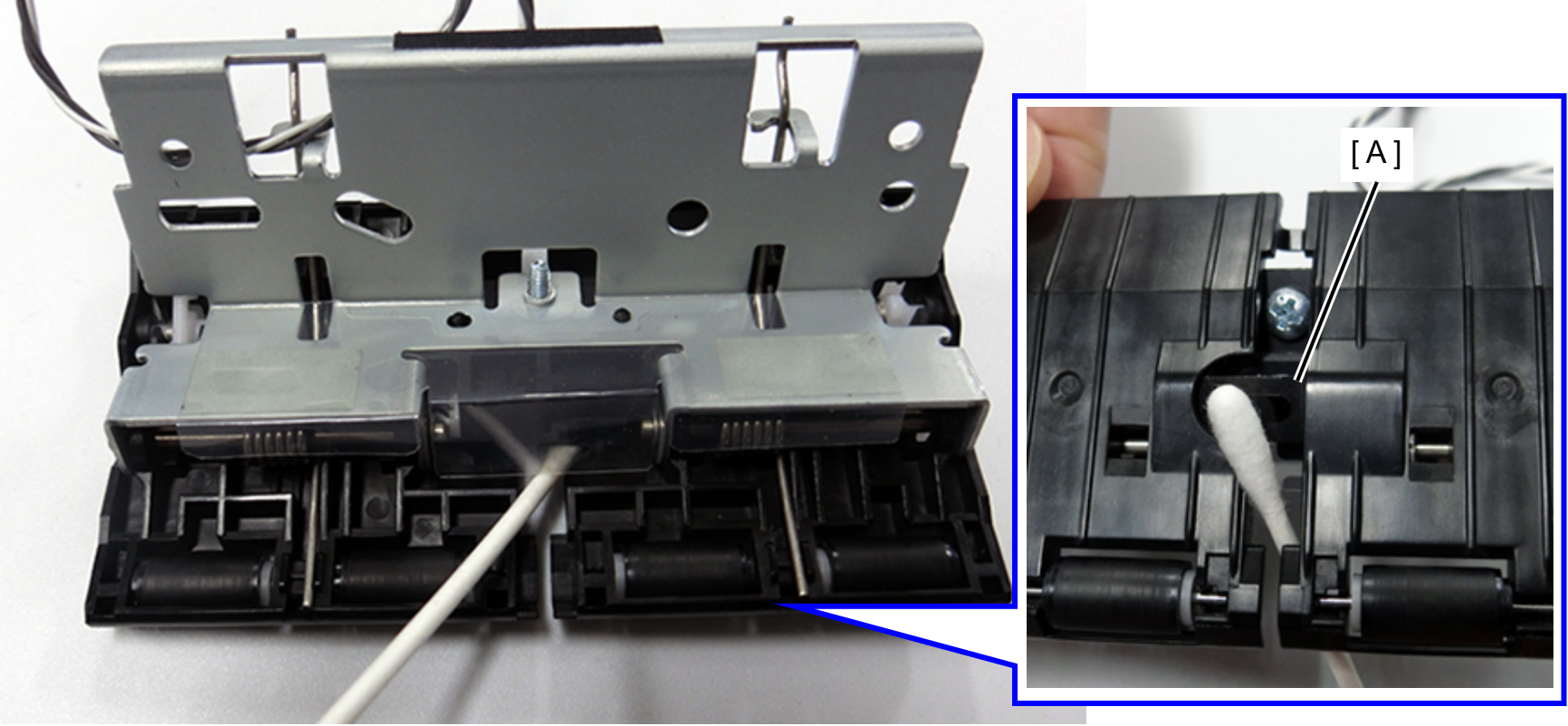
- Print a PE Sensor check pattern.
20114 PE Sensor Check Pattern Print - Perform “3020205 PE Sensor” of Failure Verification.
30202 Sensor - Open the rear cover, and remove the Duplex Print Unit.
- Place the part printed with the PE Sensor check pattern (A) directly underneath the PE Sensor (B), and check that the sensor state changes from OFF to ON.
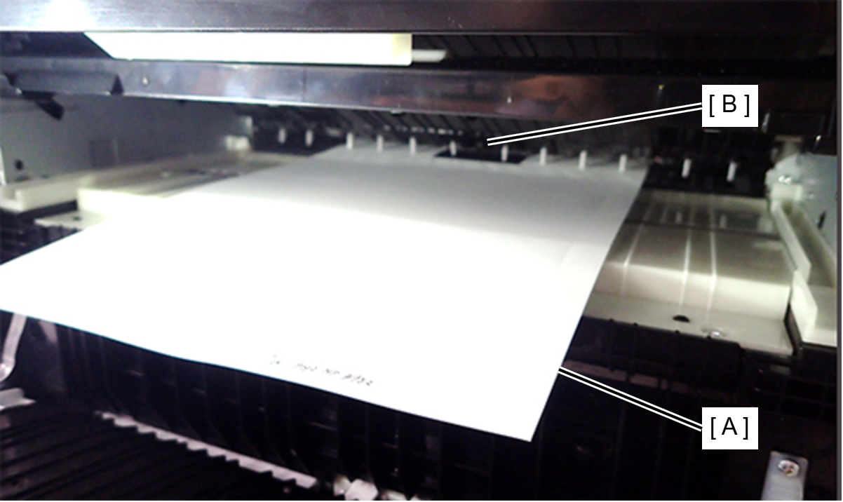
- PE Sensor Check Pattern

- PE Sensor Check Pattern
When there is no change in the sensor state, perform cleaning again.
- Assemble the product up to the product state (state where it can be activated).
- Start the product in service support mode. (Starting Service Support Mode)
- Select "04 Maintenance" from the service support mode menu.
- Select “410 Regular Maintenance”.
- Select ”41002 After performed”.