
Main Board
 Adjustment / 調整 Adjustment / 調整 |
When replacing this part, you need to run the menu from the service support mode before replacing it. |
- Remove the two screws.
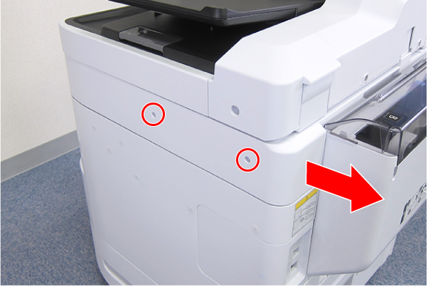
 : C.B.S-TITE-SCREW-3x8-F.ZN-3C
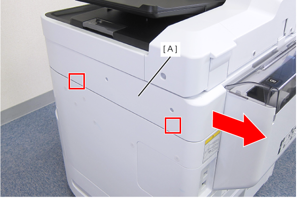
- Disengage the two hooks by sliding the Right SC Cover (A) toward the rear of the product, then remove it.
- Remove the screw.
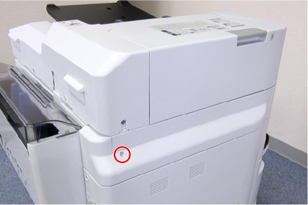
- : C.B.S-TITE-SCREW-3x8-F.ZN-3C
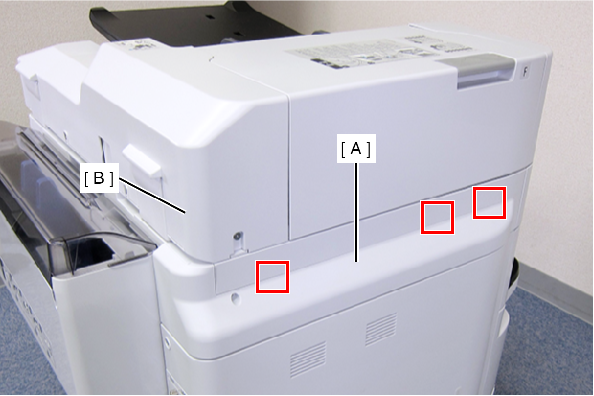
- Slide the Left SC Cover (A) toward the rear of the product to disengage the tab.
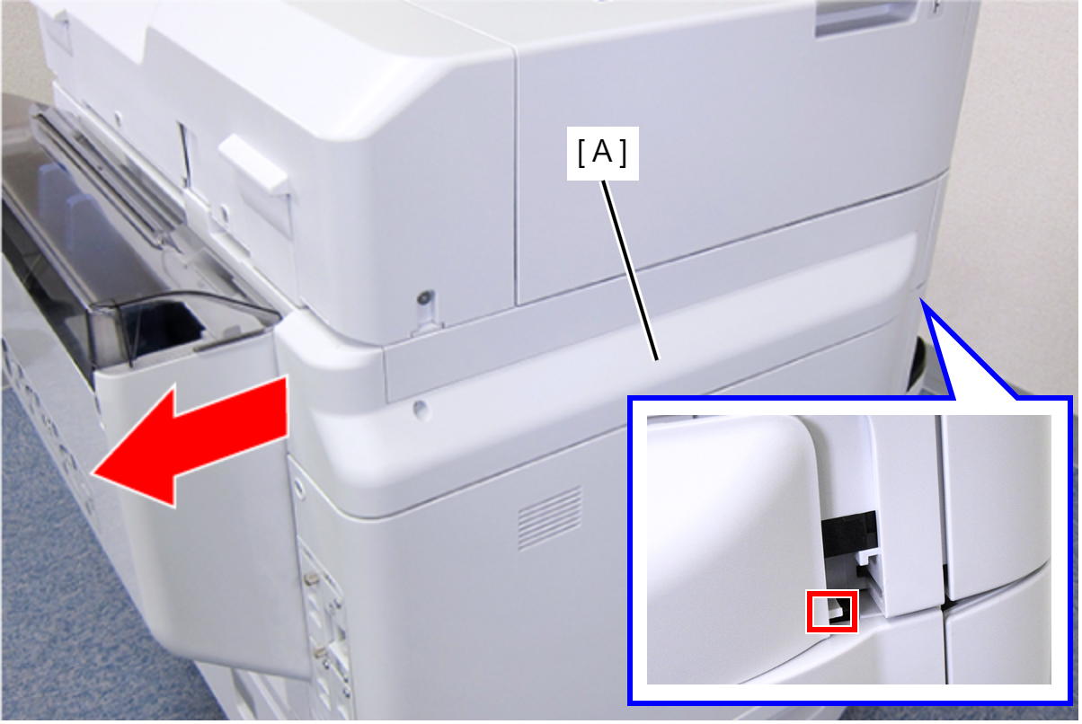
- Disengage the three tabs by inserting a flathead screwdriver into the gap between the Left SC Cover (A) and the ADF Unit (B), and then remove the Left SC Cover (A).
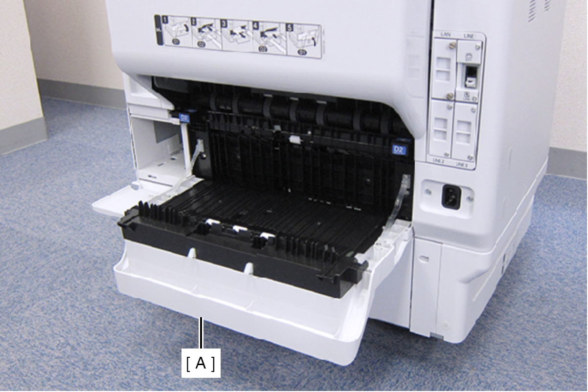
- Open the Duplex Print Cover (A).
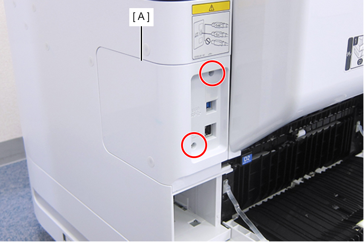
- Remove the two screws, then remove the Connector Cover (A).
- : C.B.S-TITE-SCREW-3x8-F.ZN-3C
- Remove the two screws, then remove the Right Housing Assy (A) toward the rear of the product.
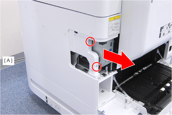
- : C.B.S-TITE-SCREW-3x8-F.ZN-3C
- Remove the two screws.
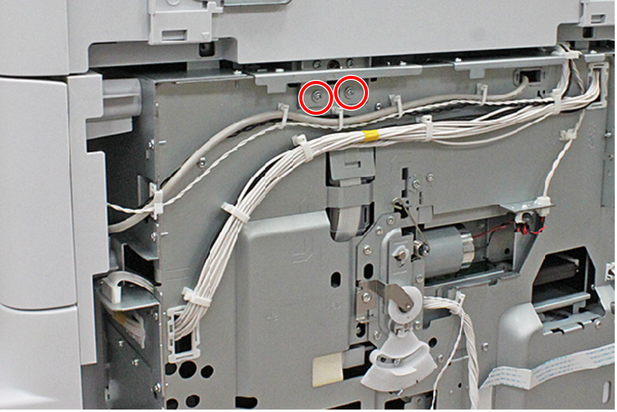
- : C.C.S-TITE-3x6-F.ZN-3C
- Raise the ADF Stopper (A) to lock the ADF Unit.
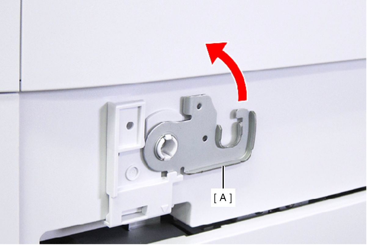
- Secure the ADF Stopper with one of the screws you removed at step 1.
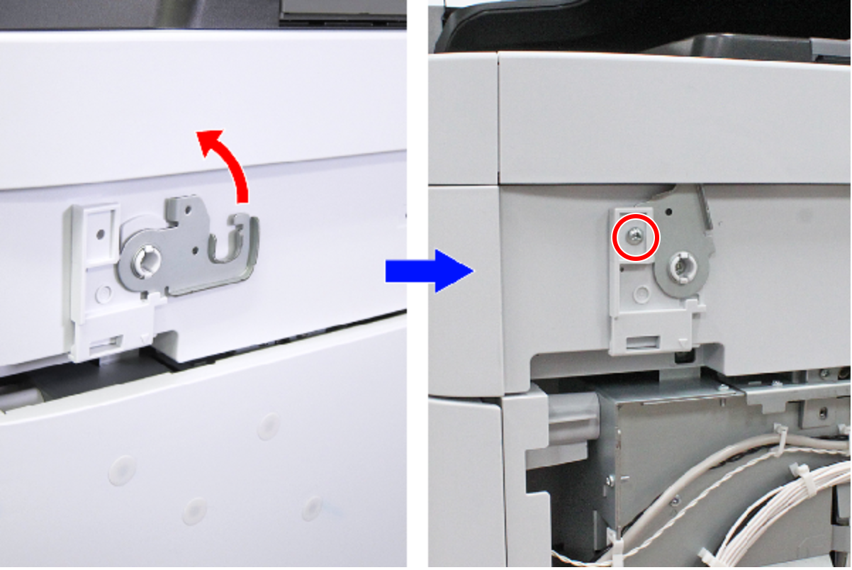
- : C.C.S-TITE-3x6-F.ZN-3C
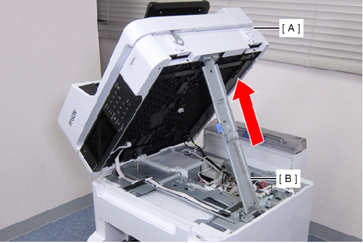
- Hold the ADF/SCN Unit (A) with both hands as shown above, and open the ADF/SCN Unit (A).
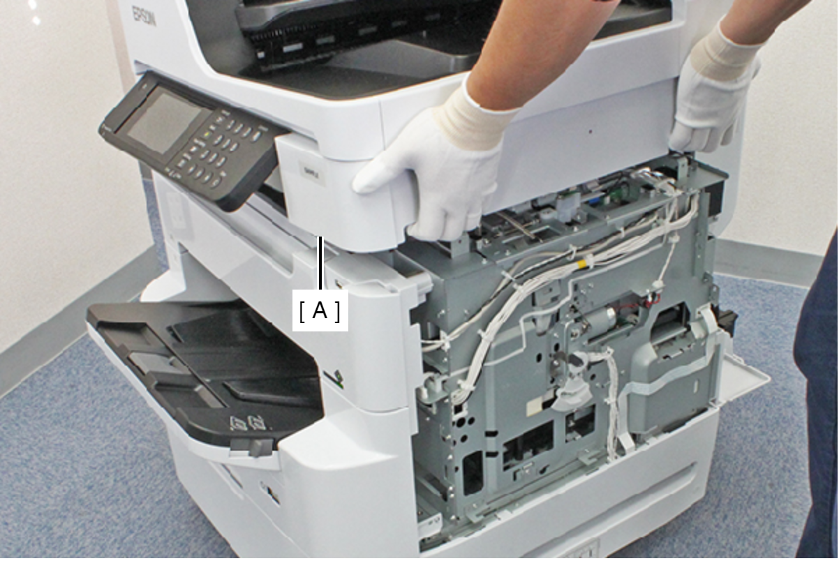
- Open the ADF/SCN Unit (A) and extend the support stand (B) as far as it goes, then support theADF/SCN Unit (A) with the support stand.
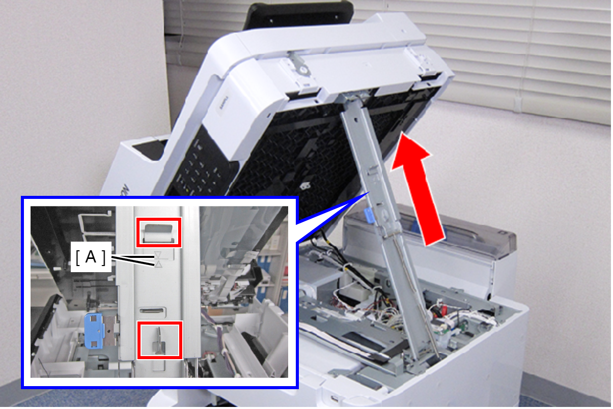
 Caution / 注意
Make sure that the extended support stand is fixed with the two hooks, and the two triangle marks face to each other.
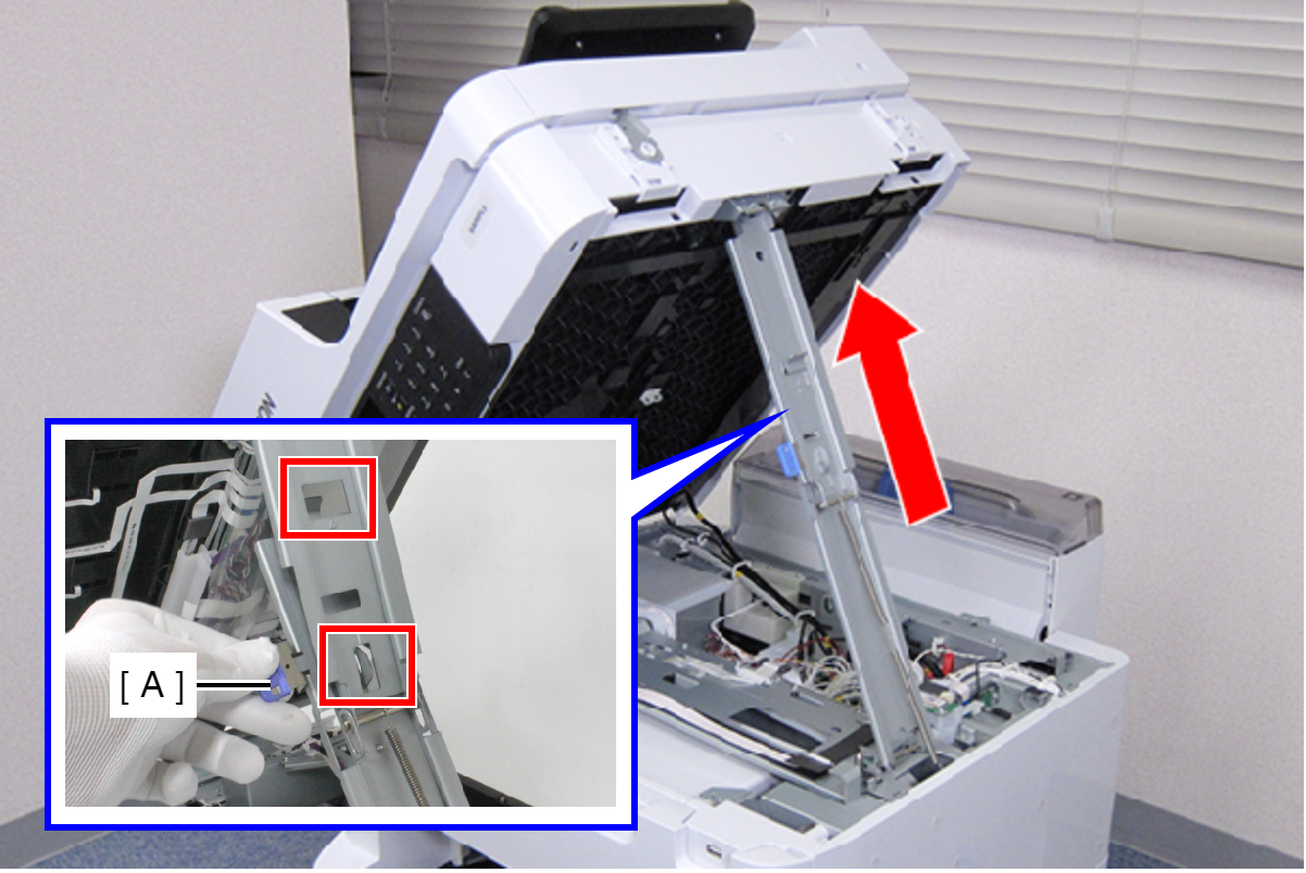
 Check Point / チェックポイント
When closing the ADF/SCN Unit, hold down the switch on the support stand and raise the ADF/SCN Unit in the direction of the arrow to disengage the two hooks, then fold the support stand.
- Remove the screw, then remove the PS Harness Holder (A).
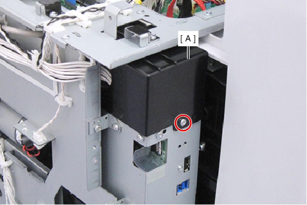
- : C.B.S-TITE-SCREW-3x8-F.ZN-3C
Disconnect the following cables and FFC from the Main Board.
- Power Supply Unit Cable (CN210) (With hook)
- Cable (CN211)
- USB Host Cable (CN106)
- Cable (CN504)
- Panel FFC (CN302)
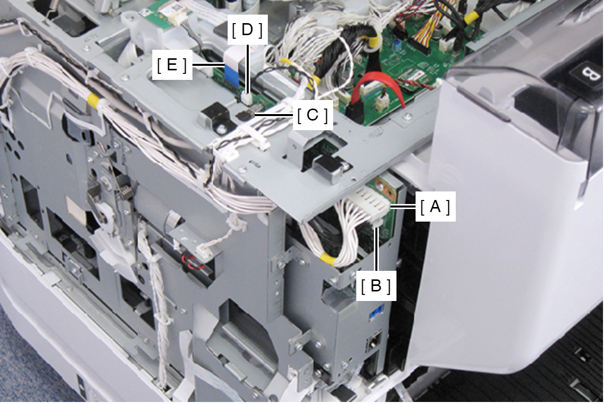
- Disconnect the CRCM FFC (B) from CN705 connector (A) on the Main Board, and then release the FFC from the clamp (C).
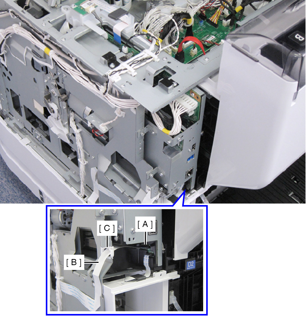
- Disconnect the MB CSIC FFC (B) from CN707 connector (A) on the Main Board, and then put the FFC under the holder (C).
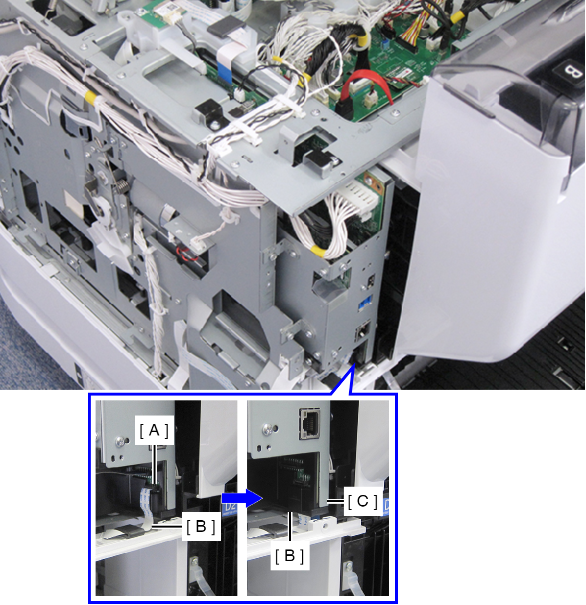
- Disconnect the cable (B) from CN102 connector (A) on the Main Board.
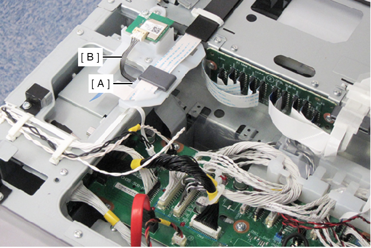
- Remove the two screws, then remove the panel cable guide (A).
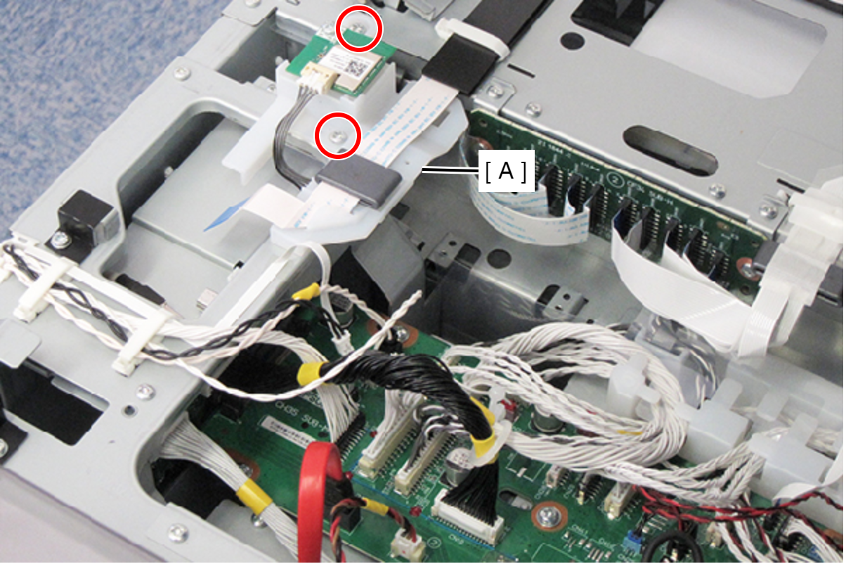
- : C.B.S-TITE-SCREW-3x8-F.ZN-3C
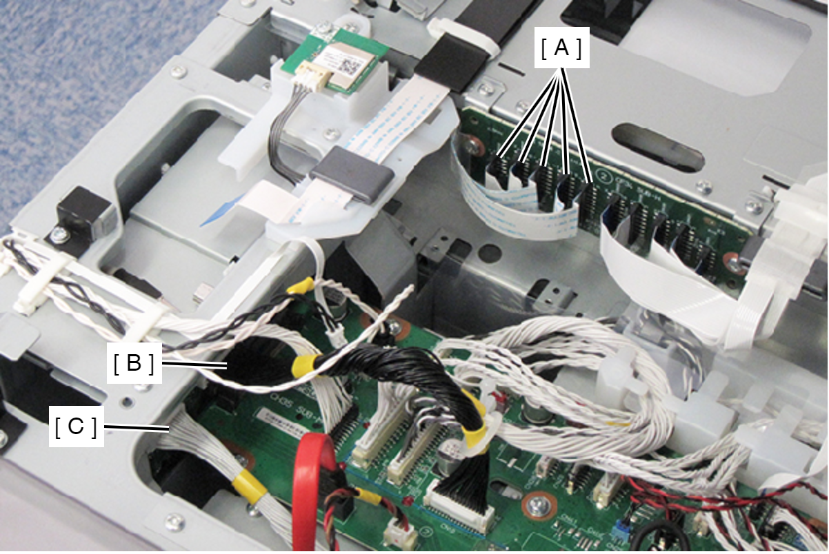
- Disconnect the following cables and FFCs.
- Head Relay FFC (CN101, CN102, CN103, CN104, CN109)
- Cable (CN501) (With hook)
- Cable (CN503) (With hook)
- Remove the screw that secures the Relay Harness Cover (A).
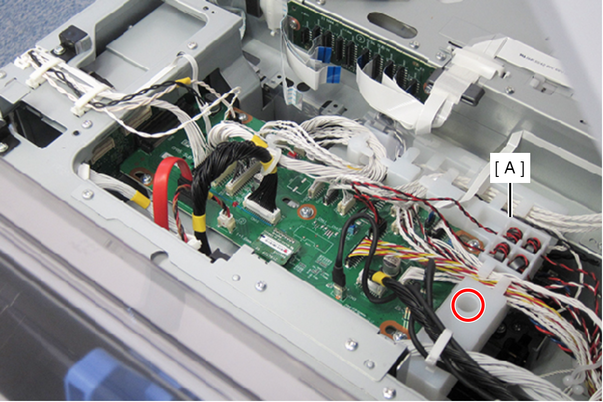
- : C.B.S-TITE.P4.SCREW-3x8-F.ZN-3C
- Remove the screw that secures the PCB Mechanism Relay Board (A).
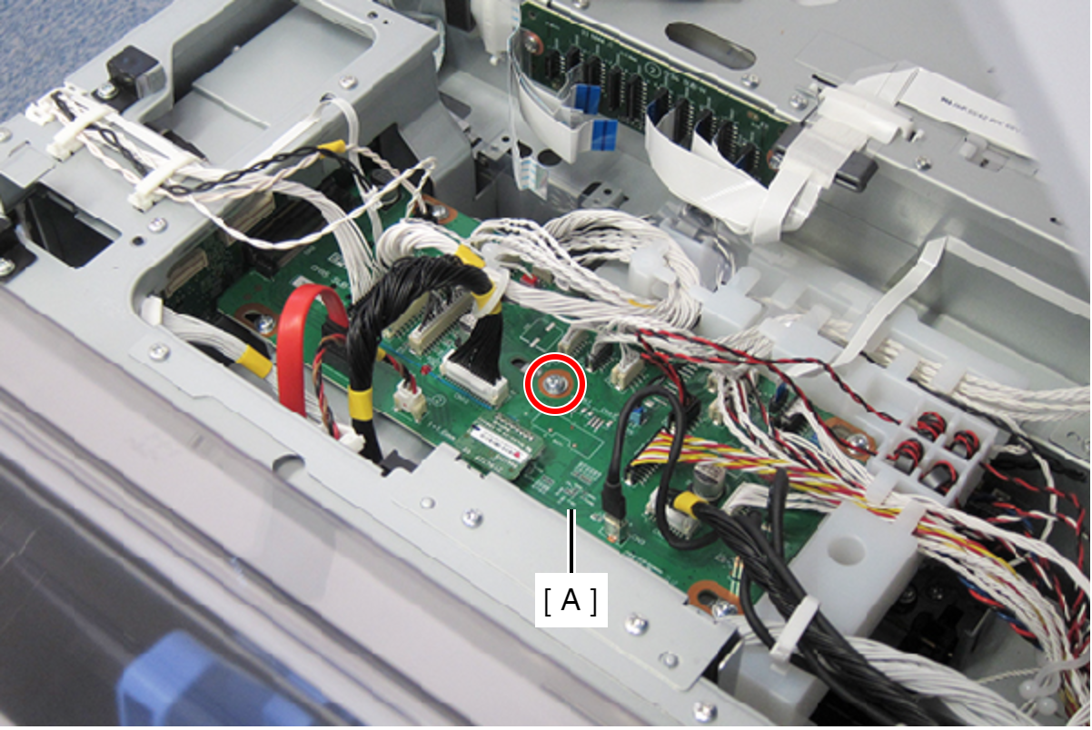
- : C.B.S-TITE.P4.SCREW-3x8-F.ZN-3C
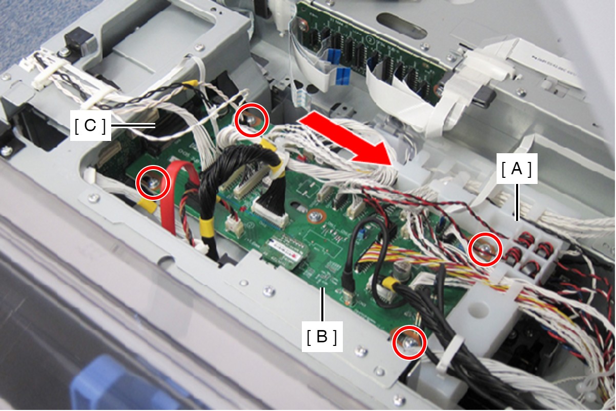
- Loosen the four screws to slide the Relay Harness Cover (A) and the PCB Mechanism Relay Board (B) in the direction of the arrow, and then disconnect the cable of PCB Mechanism Relay Board (B) from CN502 connector (C) on the Main Board.
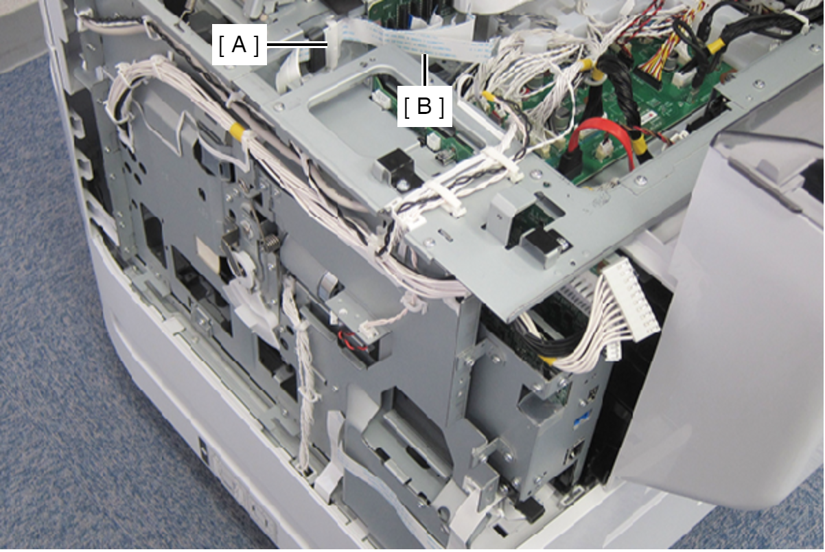
- Remove the FFC clamp (A), then release the head relay FFC (B).
- Remove the three screws, and then remove the Main Board Unit (A) in the direction of the arrow.
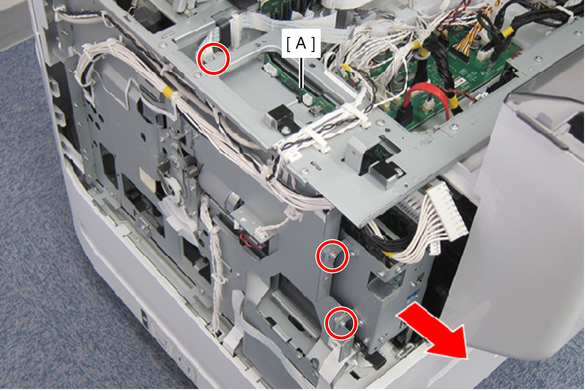
- : C.B.S-TITE-SCREW-3x8-F.ZN-3C
 Assembly / 組み立て
Connect the Head Relay FFC by the following procedure.
- Remove the FFC clamp (A) and the acetate tape.
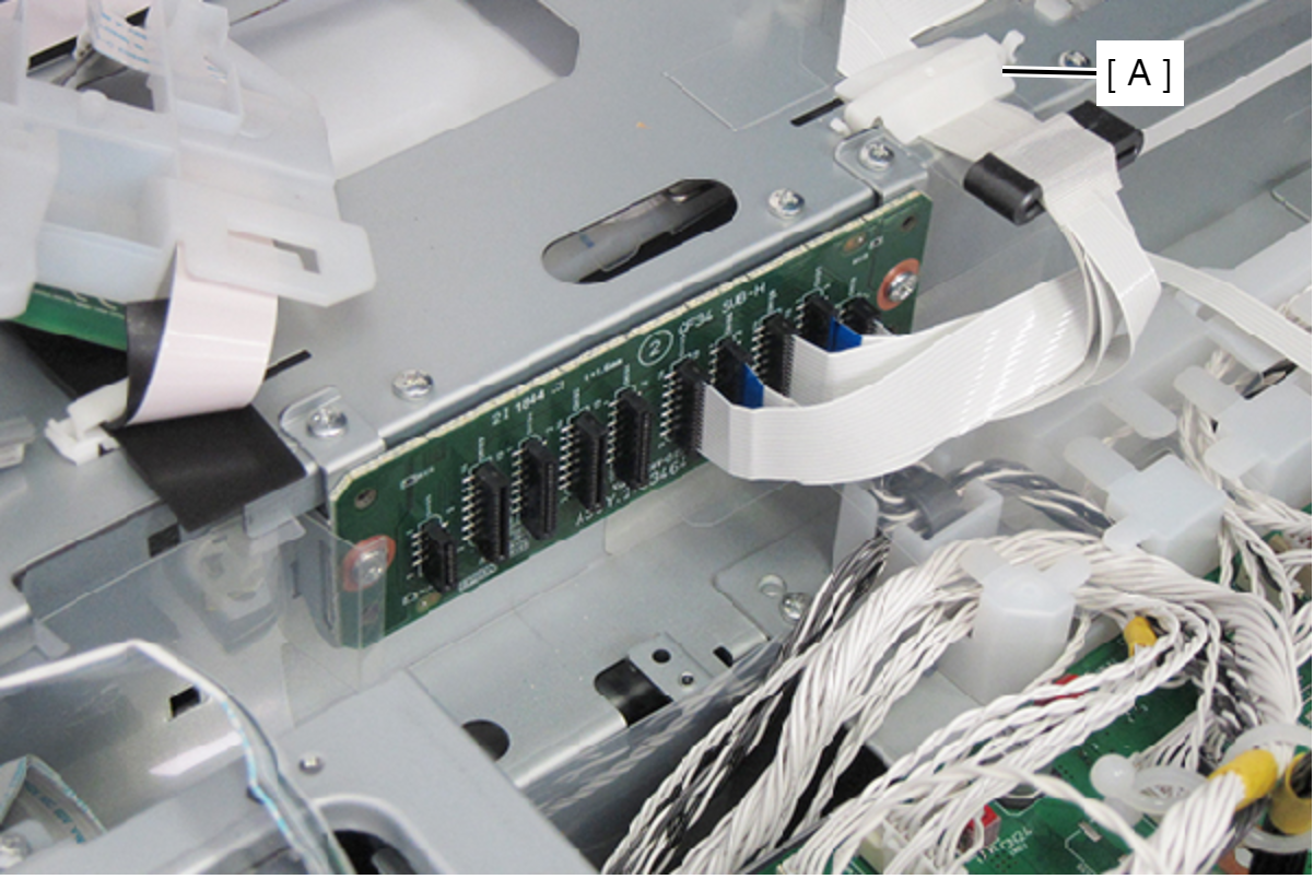
- Remove the two screws, then remove the Relay Board Assy (A).
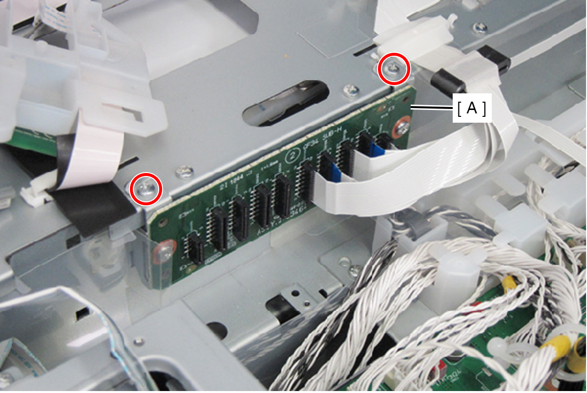
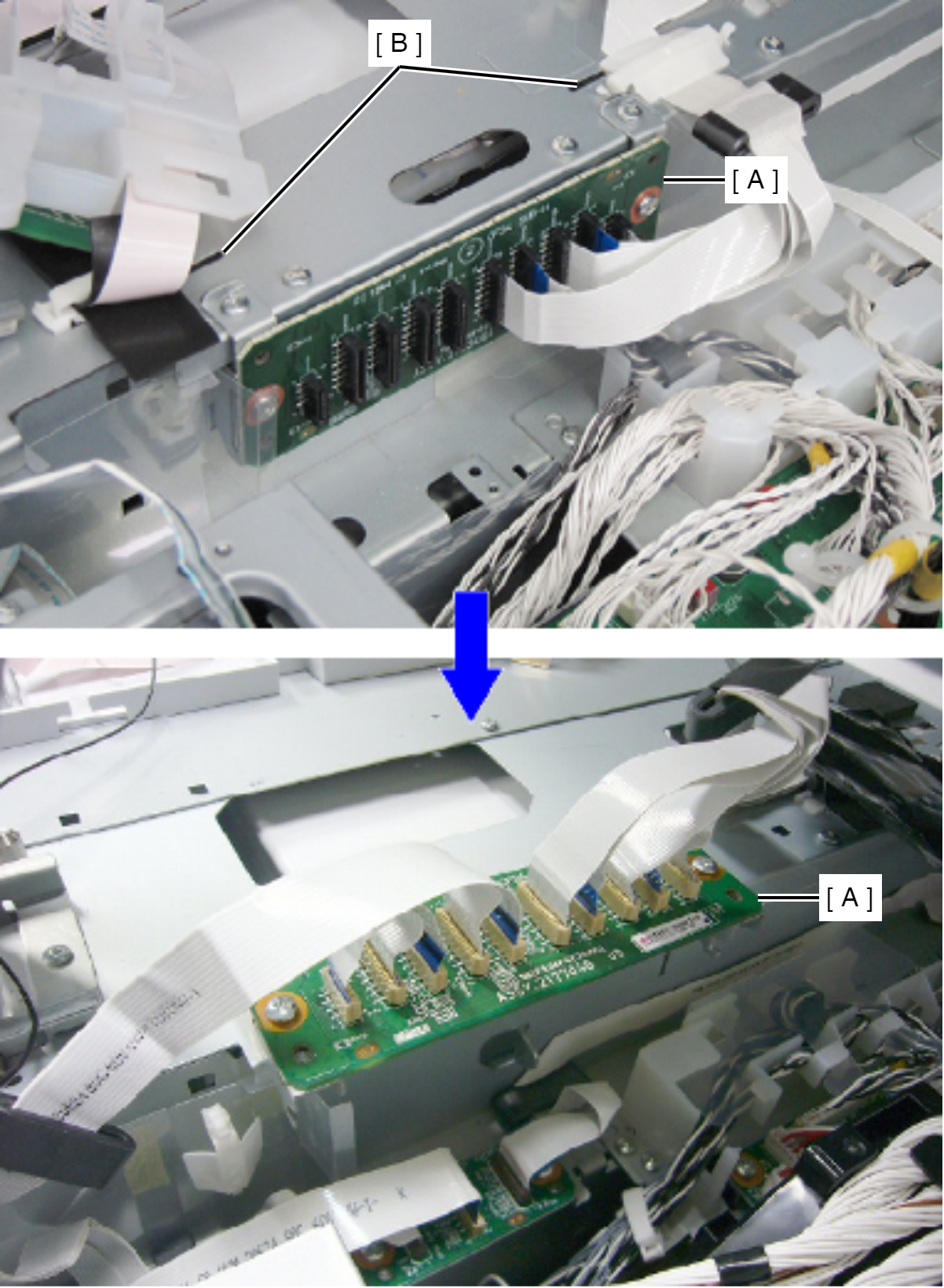
- Insert the two tabs of the Relay Board Assy (A) frame into the holes (B) on the main frame to temporarily secure the Relay Board Assy (A) with the assy facing upward.
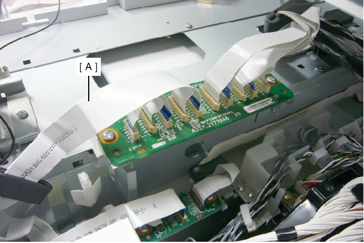
- Connect the head relay FFC. (Take care not to connect obliquely.)
- Remove the seven screws, then remove the Shieldplate MB Upper (A).
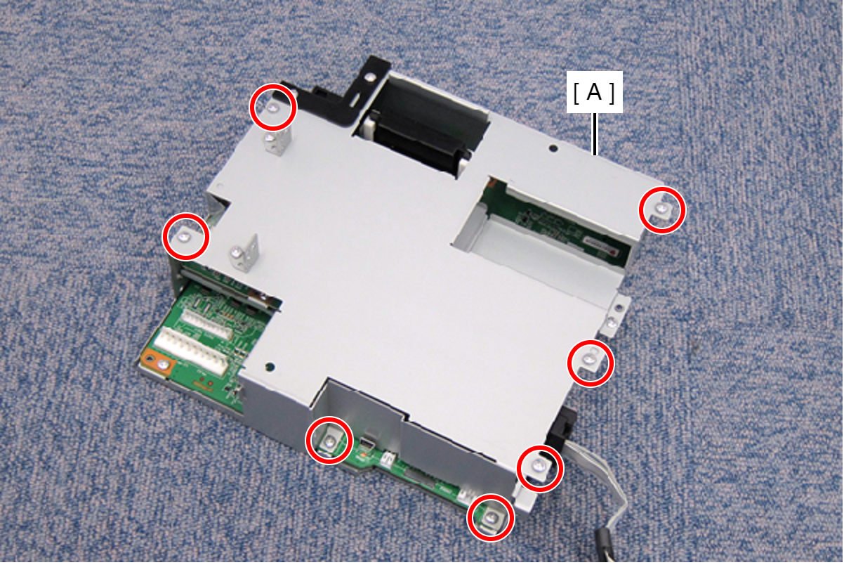
- : C.B.S-TITE-SCREW-3x8-F.ZN-3C
- Disconnect the FFC from CN107 connector (B) on the Main Board (A).
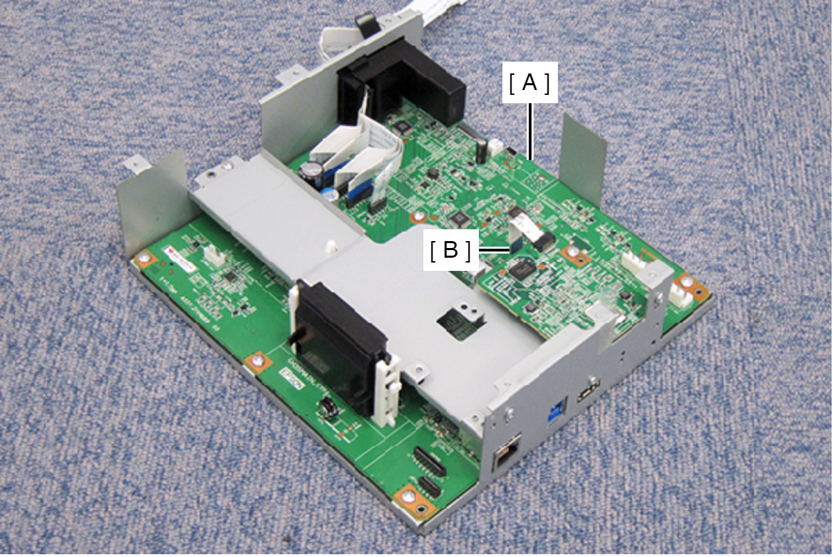
- Remove the three screws, then remove the PDL FAX Assy (A).
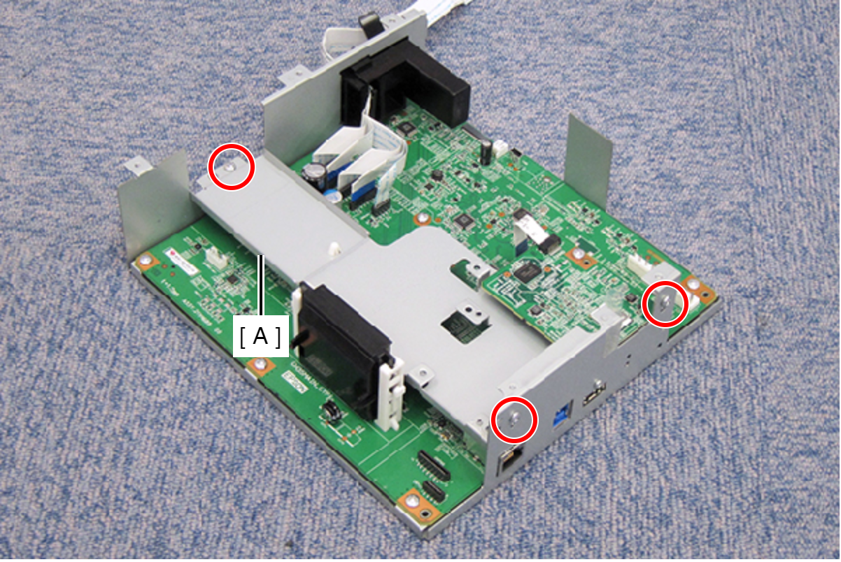
- : C.B.S-TITE-SCREW-3x8-F.ZN-3C
- Remove the PCB ROM (B) from the Main Board (A).
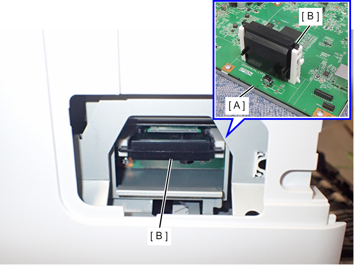
Caution / 注意In the event of PCB ROM malfunction, necessary data must be written to the PCB ROM (this is not possible at the repair site), so please contact the Epson Service Support department. For recovery, the PCB ROM and the Main Board installed at the time of malfunction will be required. Do not dispose of the removed PCB ROM or Main Board.
Check Point / チェックポイントThe PCB ROM retains all data within the printer. Therefore, the data can be easily transferred by replacing the PCB ROM.
- Remove the Main Board (A).
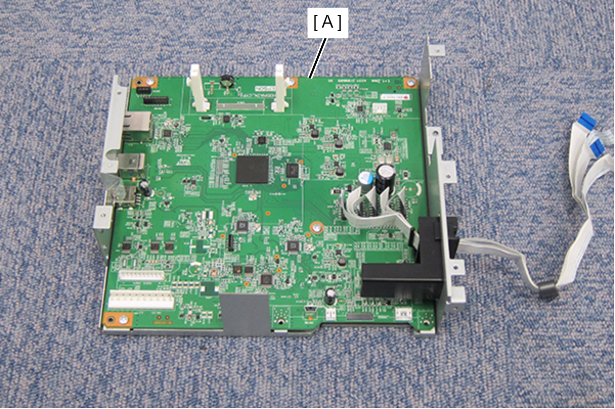
Assembly / 組み立てDuring assembly, be sure to install the PCB ROM that was used, in which the printer data is stored, to the Main Board.
| Adjustment / 調整 |
After replacing this part, you need to run the menu from the service support mode. (If you ran the Before-replacement menu before replacing the part, it will start automatically when you turn the power on.) |