
Upper Connector
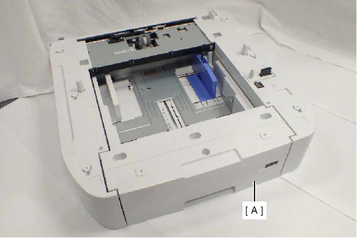
- Remove the Printer Main Unit from Option Cassette Unit (A).
- Remove the four screws, then remove the Option Right Cover (A).
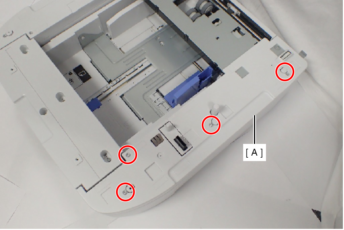
 : C.B.P-TITE-SCREW-3x10-F.ZN-3C
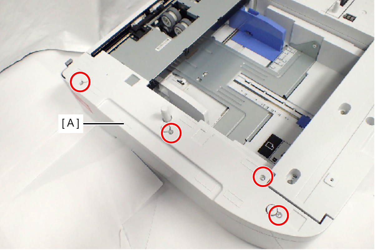
- Remove the four screws, then remove the Option Left Cover (A).
- Remove the two screws, then remove the Option Rear Fitting Frame (A).
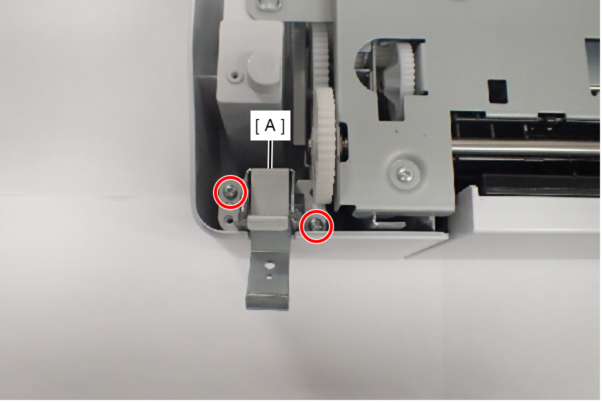
- : C.B.P-TITE-SCREW-3x10-F.ZN-3C
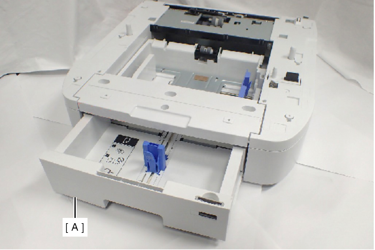
- Remove the Option Paper Cassette (A).
- Remove the two screws, and remove the Grounding Frame Assy (A).
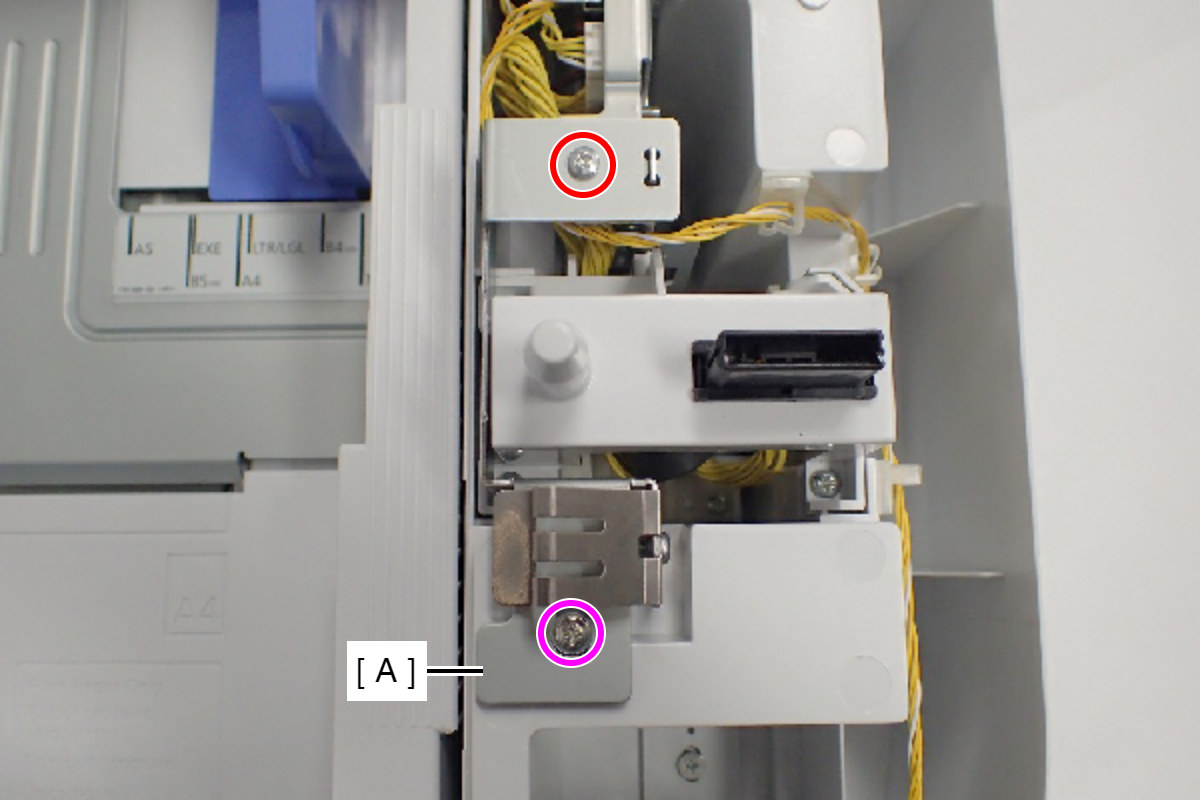
- : C.B.S-TITE-SCREW-3x6-F.ZN-3C
 : C.C.P-TITE-SCREW-3x8-F.ZN-3C
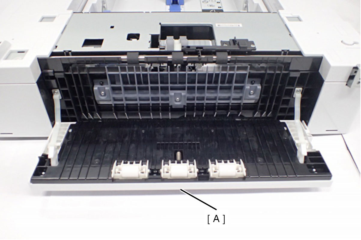
- Open the Option Rear Cover (A).
- Remove the five screws fixing the Cassette Drawers.
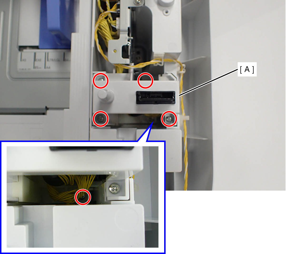
- : C.B.P-TITE-SCREW-3x10-F.ZN-3C
- Remove the five screws fixing the Option Drive Frame Assy (A).
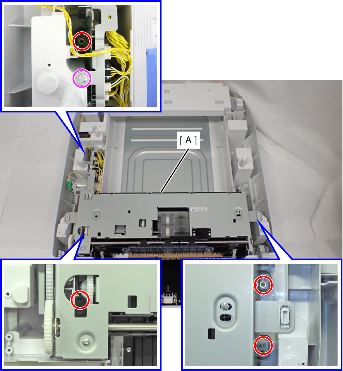
- : C.POLWAVE.D-TITE-A-SCREW-3x6-F.ZN3C
- : C.C.P-TITE-SCREW-3x8-F.ZN-3C
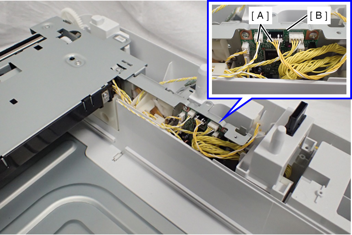
- Disconnect the two cables (A) from the Option Cassette Board (B).
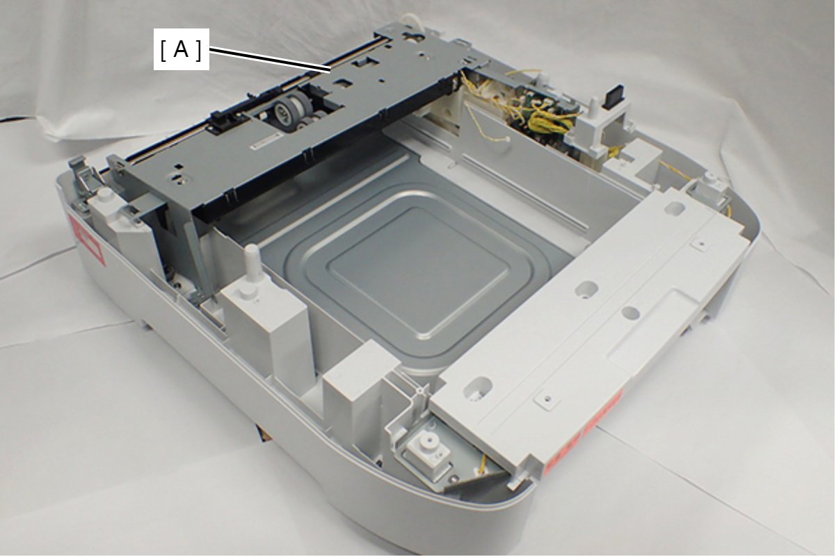
- Remove the Option Drive Frame Assy (A).
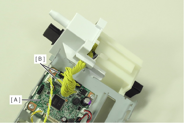
- Remove the cable from the connector (CN1, CN2) (B) of the board (A).
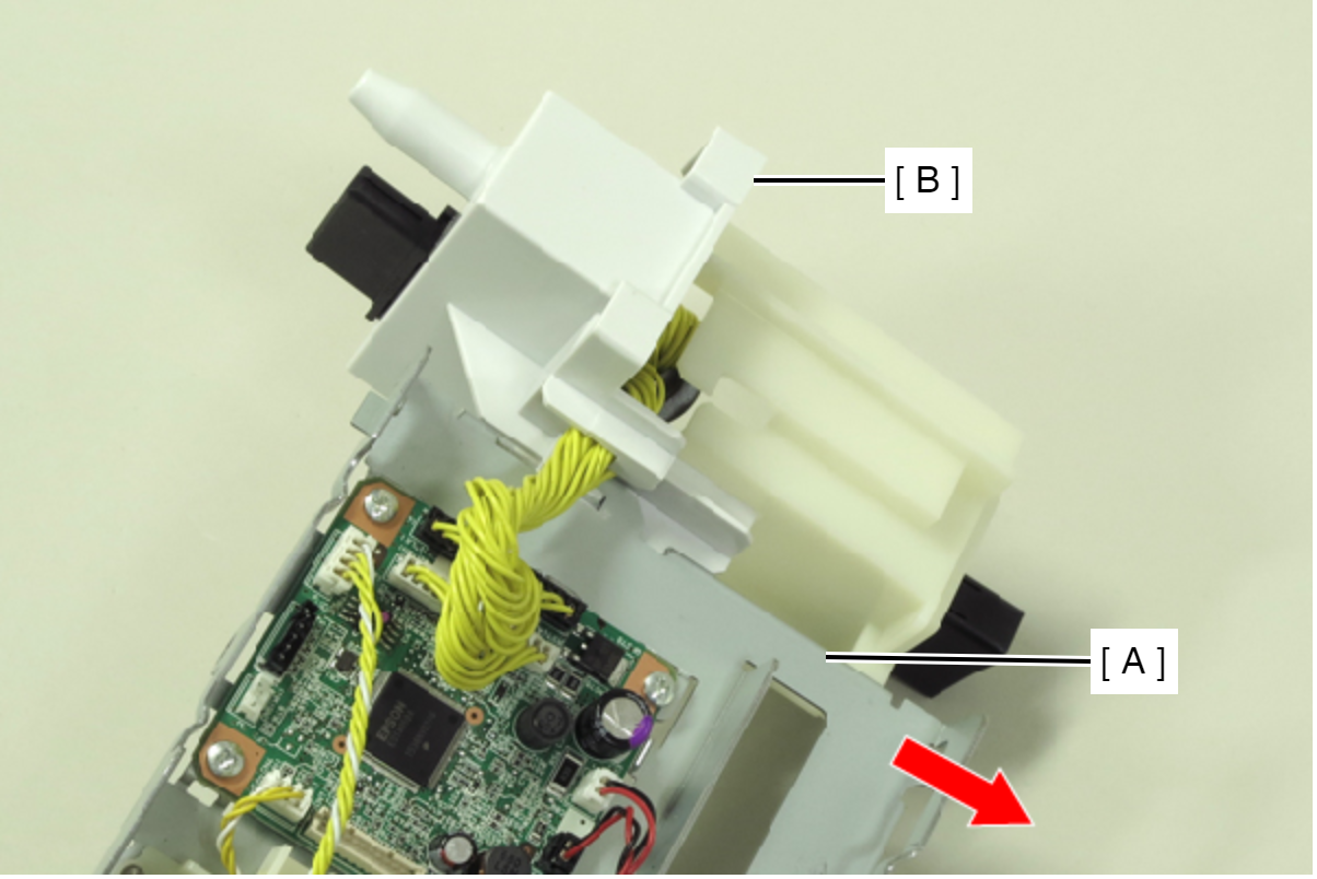
- Slide the Option Drive Frame Assy (A) in the direction of the arrow, and remove the Connector Assy (B).
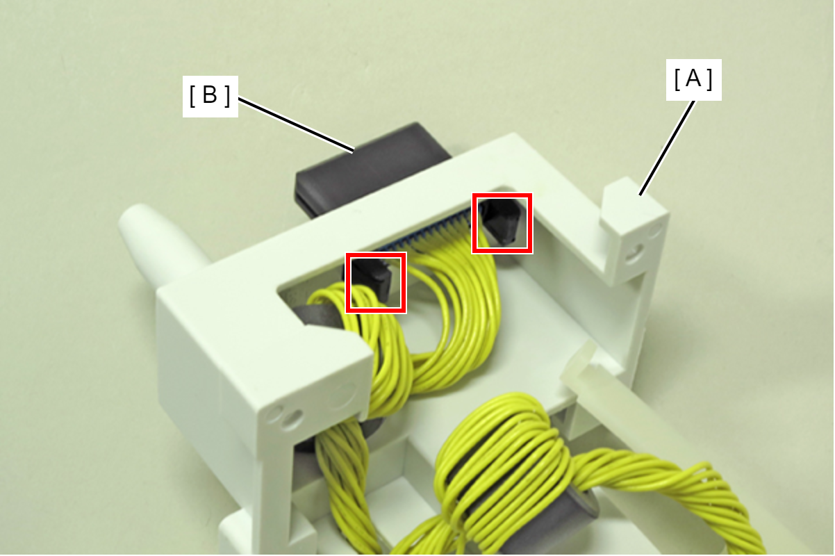
- Disengage the two hooks, then remove the Upper Connector (B) from the Cassette Assy (A).
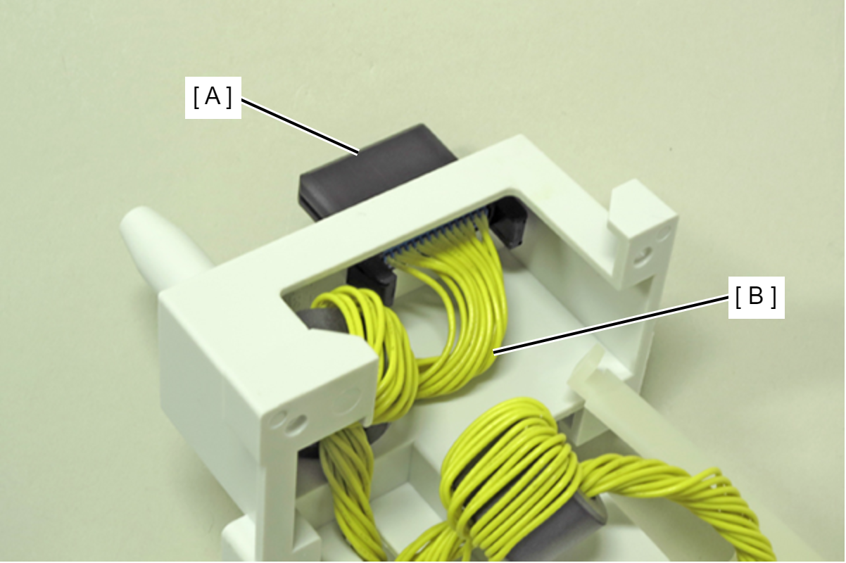
- Disconnect the cables (B) from the Upper Connector (A).
-
 : C.B.P-TITE-SCREW-3x10-F.ZN-3C