
APG Drive Assy
 Adjustment / 調整 Adjustment / 調整 |
When replacing this part, you need to run the menu from the service support mode before replacing it. |
- Remove the three screws, then remove the Left Housing Assy (A) toward the rear of the product.
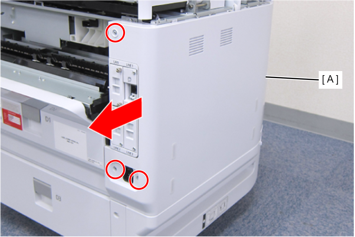
 : C.B.S-TITE-SCREW-3x8-F.ZN-3C
- Remove the screw on the rear side of the product, then remove the Paper Jam Clear Cover Holder (A).
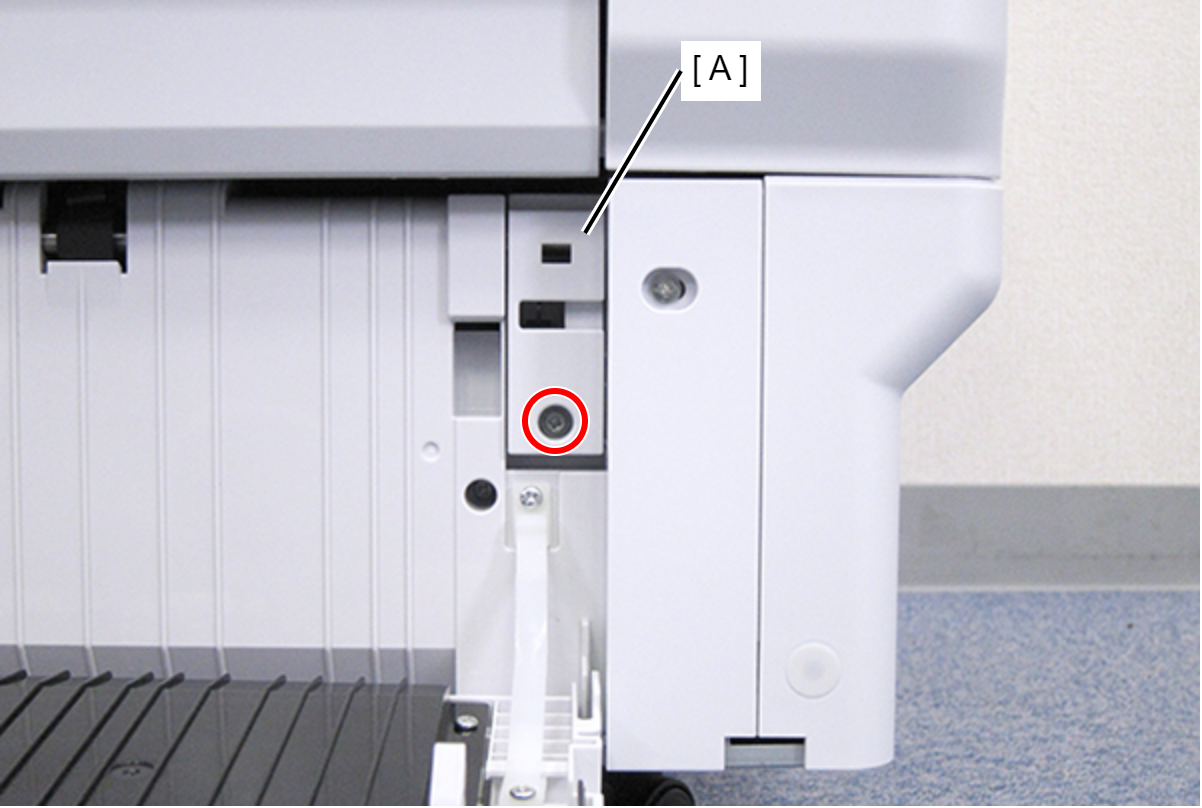
- : C.B.S-TITE-SCREW-3x8-F.ZN-3C
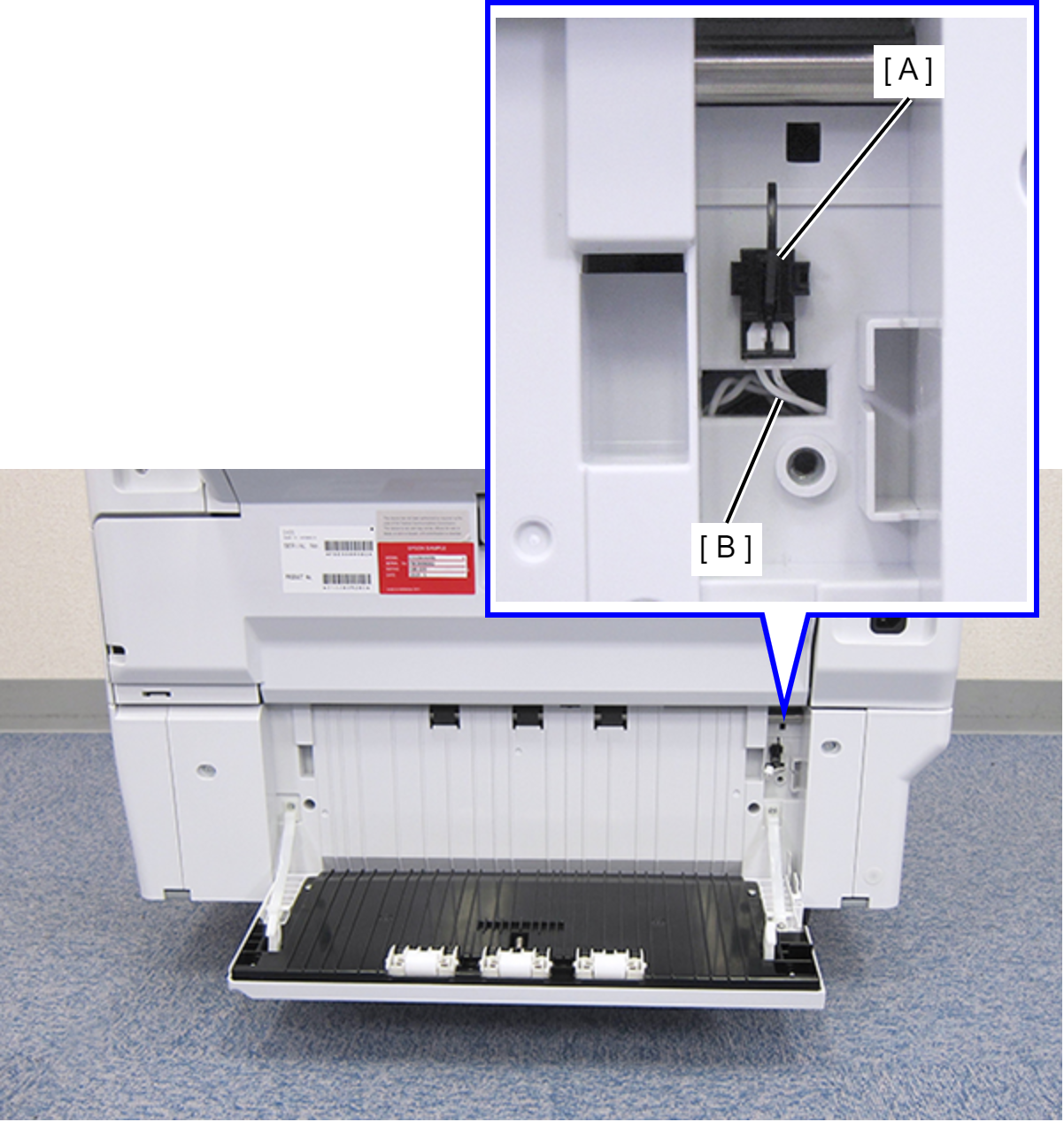
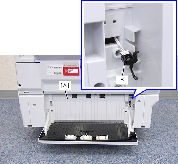
- Disconnect the cable (B) from the connector of the Paper Jam Clear Cover Sensor (A).
- Remove the four screws that secure the Rear RIPS Housing Assy (A).
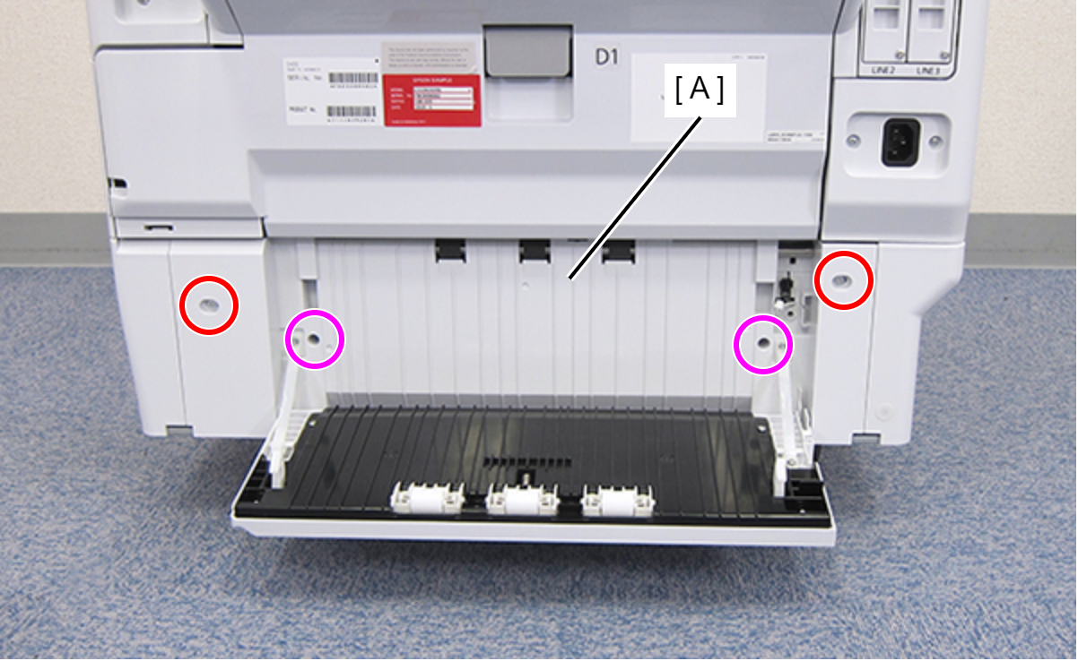
 : C.SHOULDER S-TITE,3X5
 : C.B.P-TITE-SCREW-3x10-F.ZN-3C
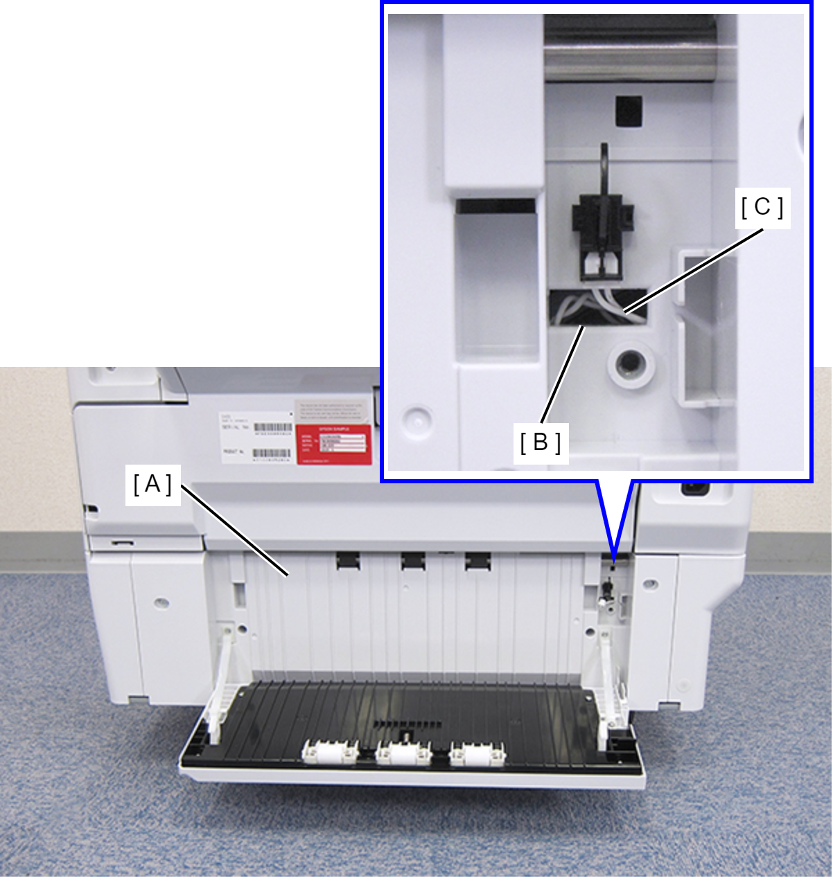
- Remove the Rear RIPS Housing Assy (A) pulling out the cable (C) through the hole (B) of the assy.
 Assembly / 組み立て
Before reinstalling the Rear RIPS Housing Assy (A), remove the Paper Jam Clear Cover Sensor (B). After connecting the cable, install the sensor to the Rear RIPS Housing Assy.
- Remove the two screws on each side.
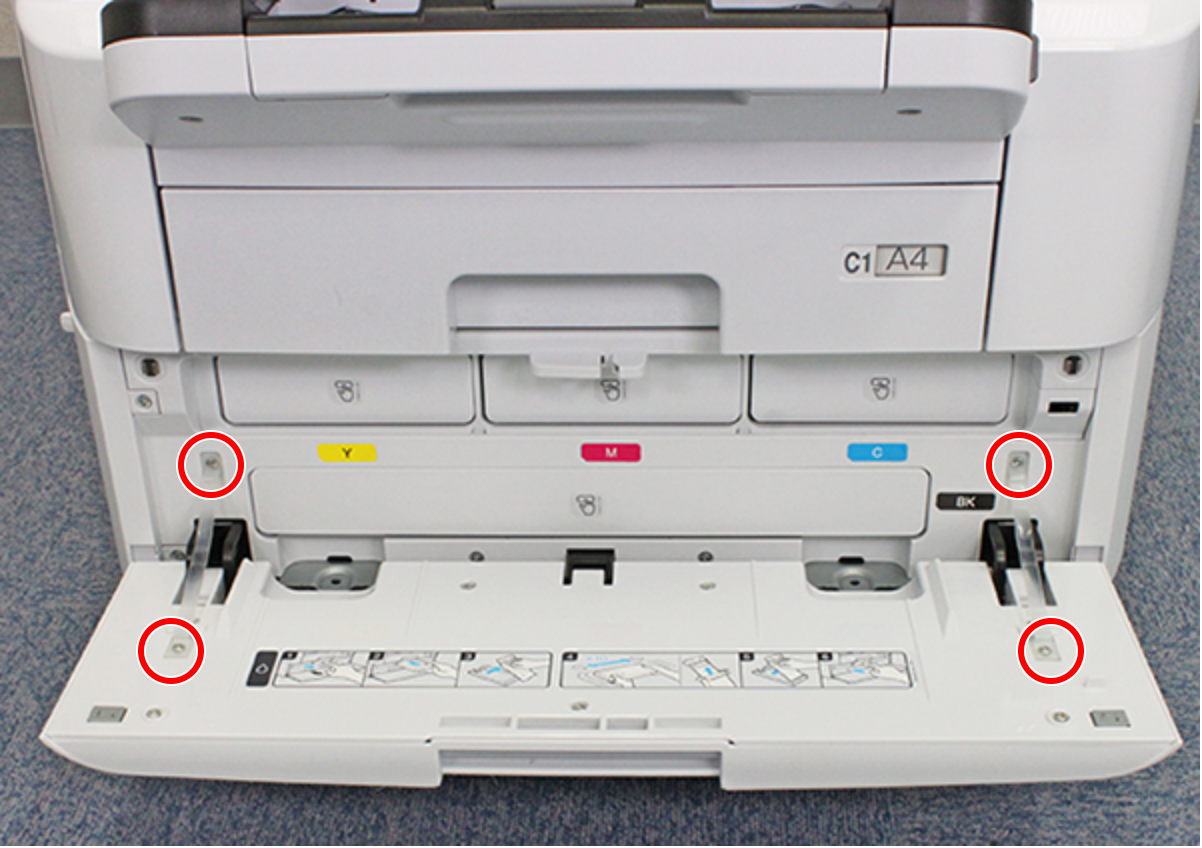
- : C.B.P-TITE-SCREW-3x10-F.ZN-3C
- Release the two hooks on each side and remove the two Ink Pack Cover Belts (A).
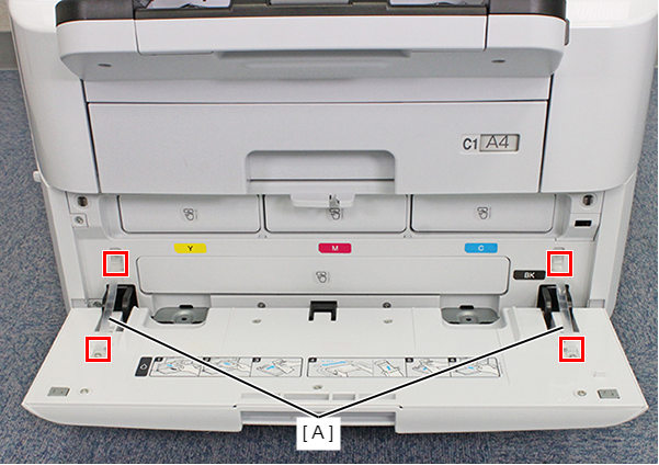
- Release each hook and remove the two Hinge Covers (A).
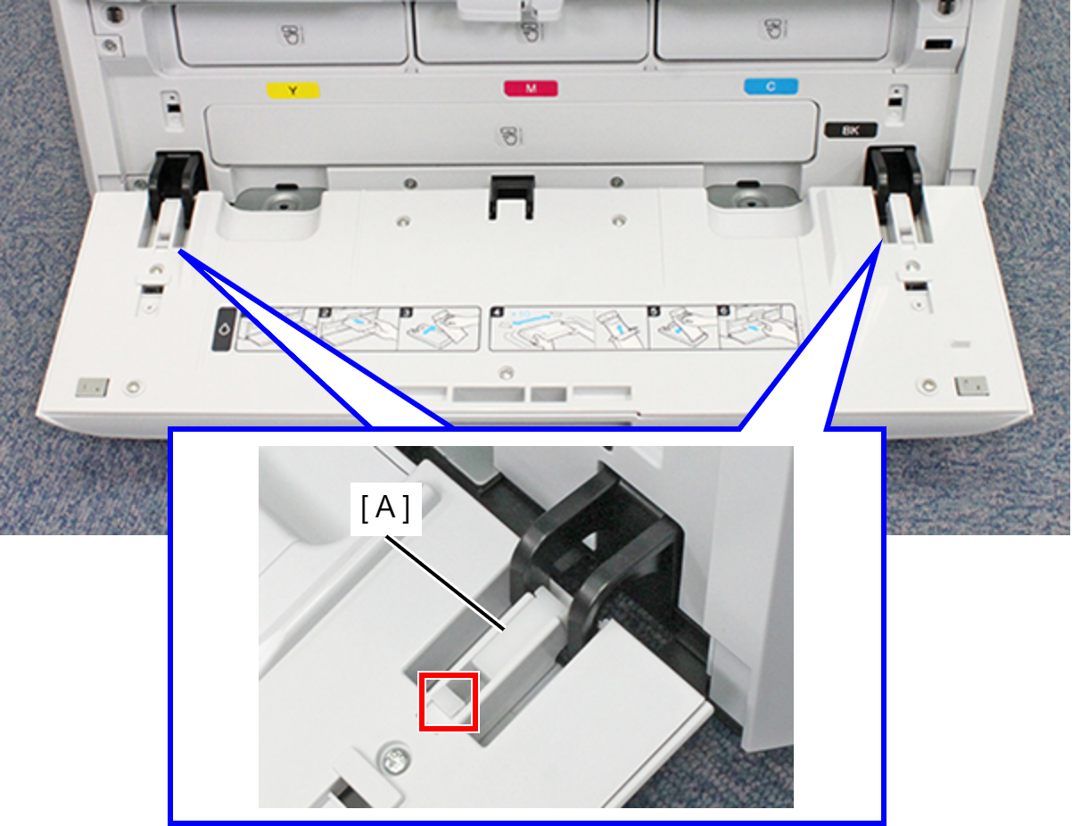
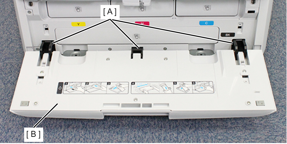
- Remove the Ink Pack Cover (B from the three hinges (A).
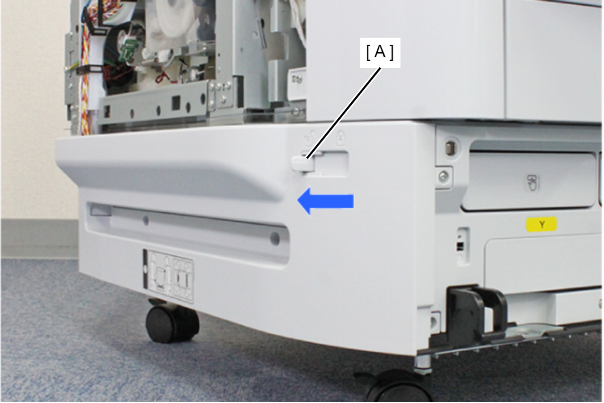
- Move the Lock Lever (A) in the direction of the arrow to set the Ink Pack Cover lock in the released state.
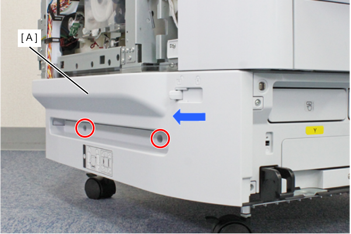
- Remove the two screws fastening the Left RIPS Housing Assy (A).
- : C.SHOULDER S-TITE,3X5
- Remove the two screws fastening the Left RIPS Housing Assy (A).
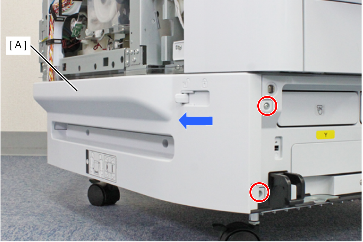
- : C.B.P-TITE-SCREW-3x10-F.ZN-3C
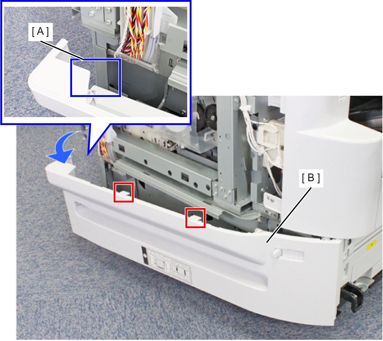
- Lift the Left RIPS Housing Assy (B) and rotate in the direction of the arrow while releasing the two hooks to release the interfering unit (A) behind the Left RIPS Housing Assy (B).
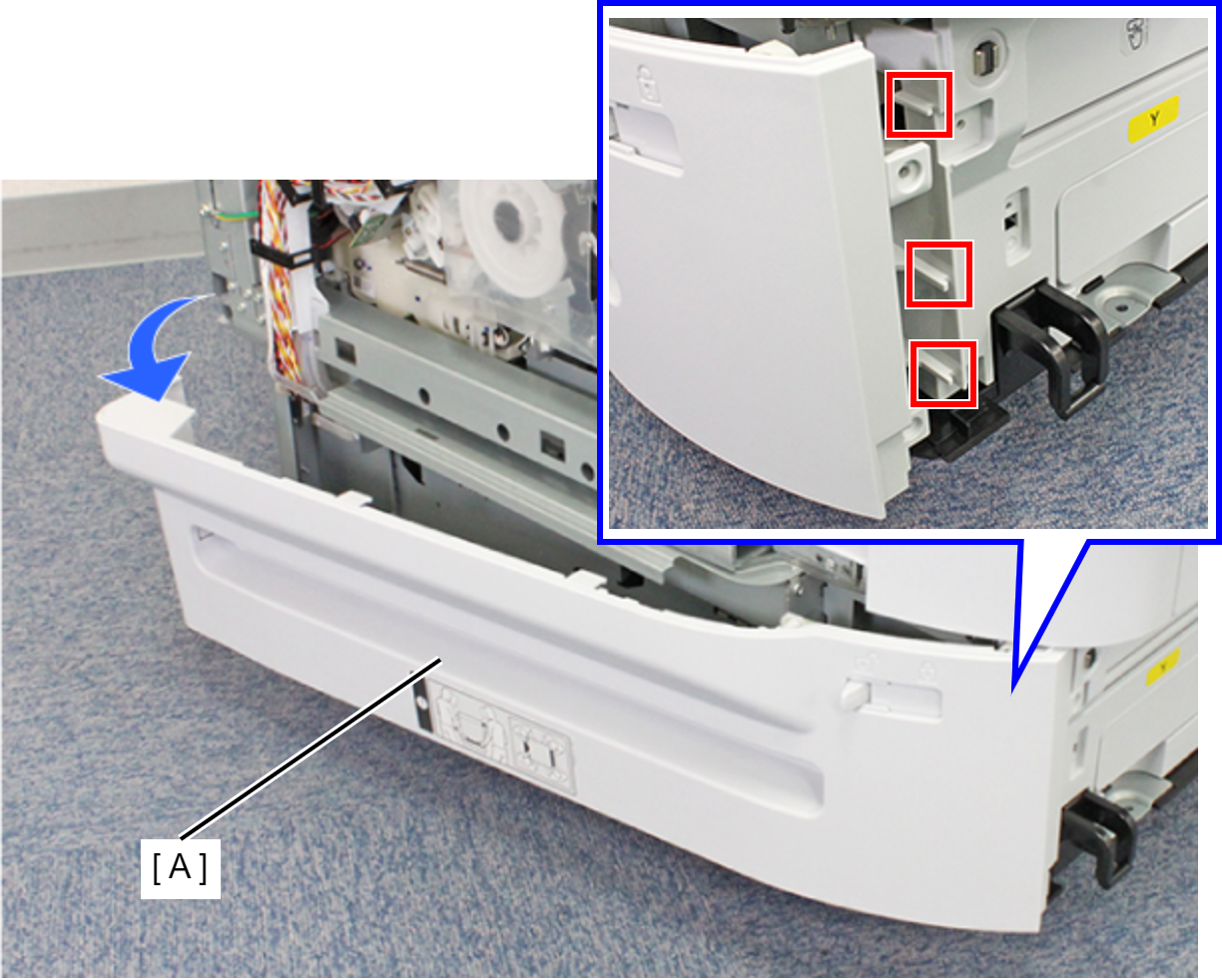
- Remove the three ribs and remove the Left RIPS Housing Assy (A).
 Assembly / 組み立て
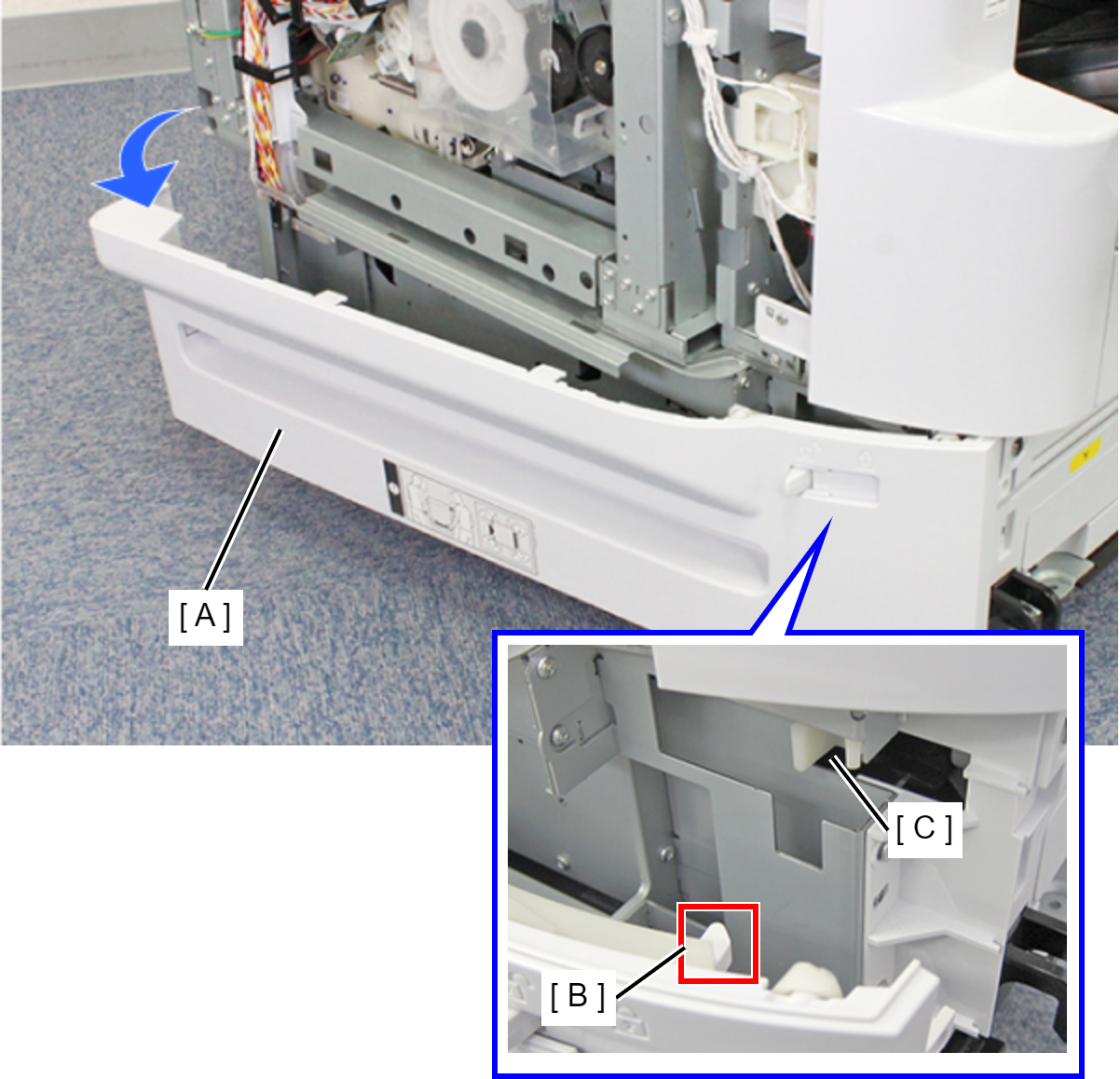
When mounting the Left RIPS Housing Assy (A), mount by aligning the Lock Lever Shaft (B) and the receiving part (C).
- Remove the two screws, then remove the Rear ASF Unit (A).
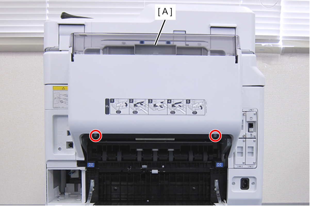
- : C.SHOULDER S-TITE,3X5
- Remove the two screws, and remove the I/F Housing Bracket (A).
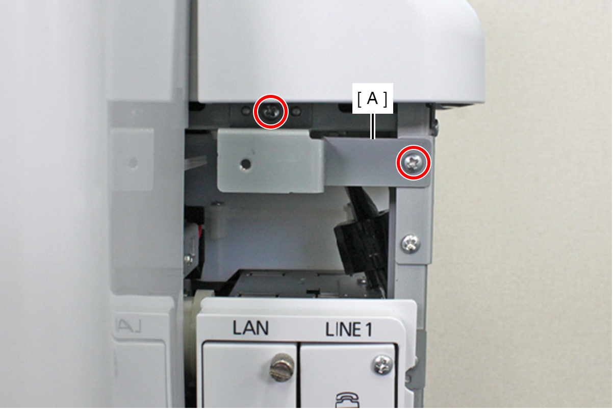
- : C.B.S-TITE-SCREW-3x8-F.ZN-3C
Remove the cable from the connector (CN7) (B) of the I/F Port Assy (A) while releasing the hook.
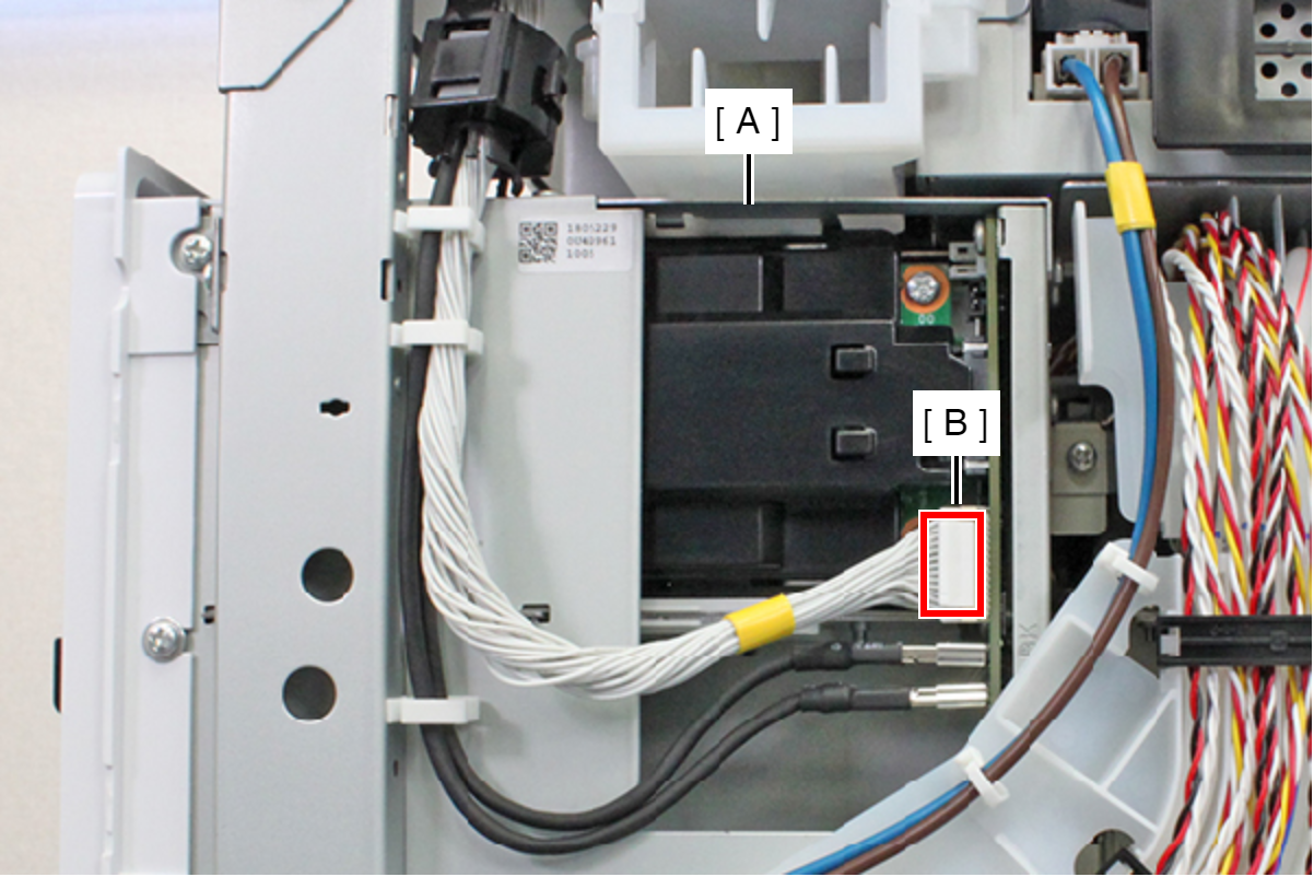
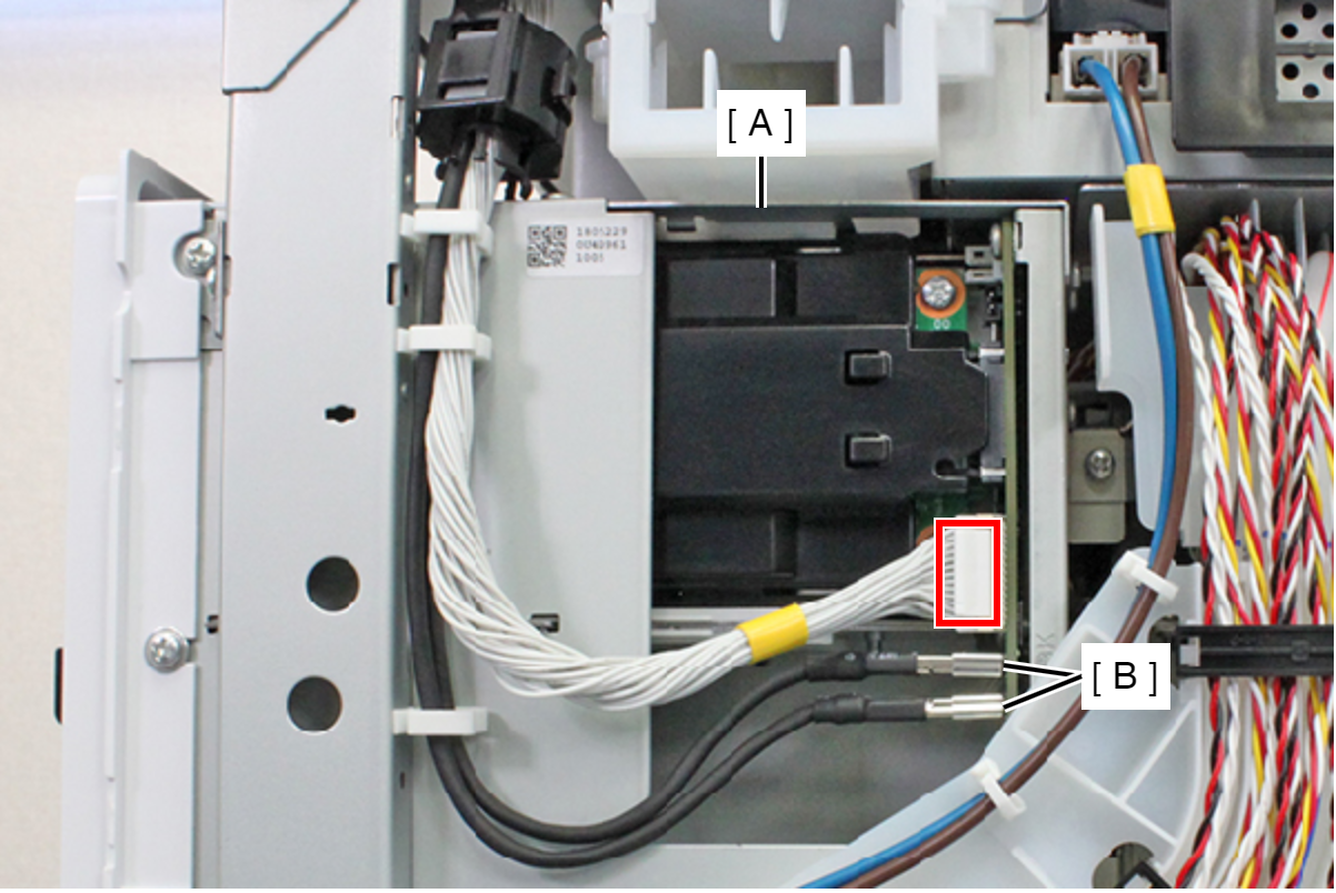
- Remove the cable from the connectors (CN5, CN6) (B) of the I/F Port Assy (A).
- Remove the four screws, and remove the I/F Port Assy (A).
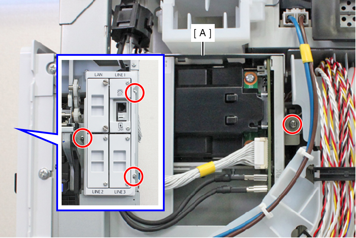
- : C.B.S-TITE-SCREW-3x8-F.ZN-3C
- Remove the screw, and retract the Tube Guide to the back face side.
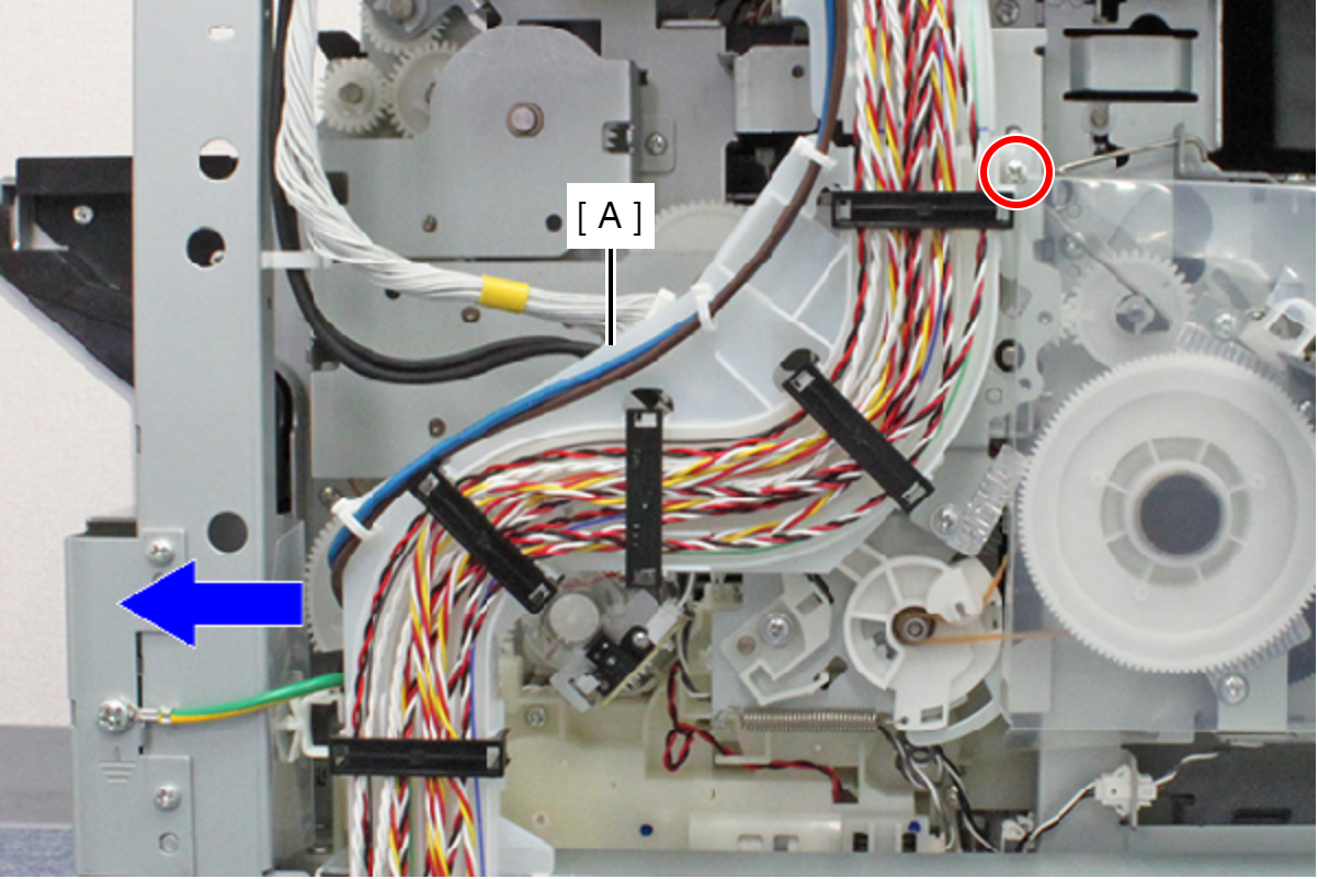
- : C.B.S-TITE-SCREW-3x8-F.ZN-3C
- Remove the hole from the screw feet (A) and pull out the folded portion (C) of the PF Scale Protection Material (B).
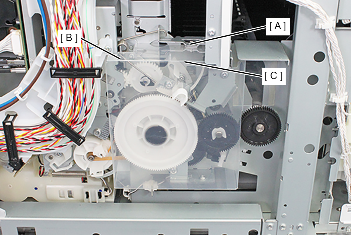
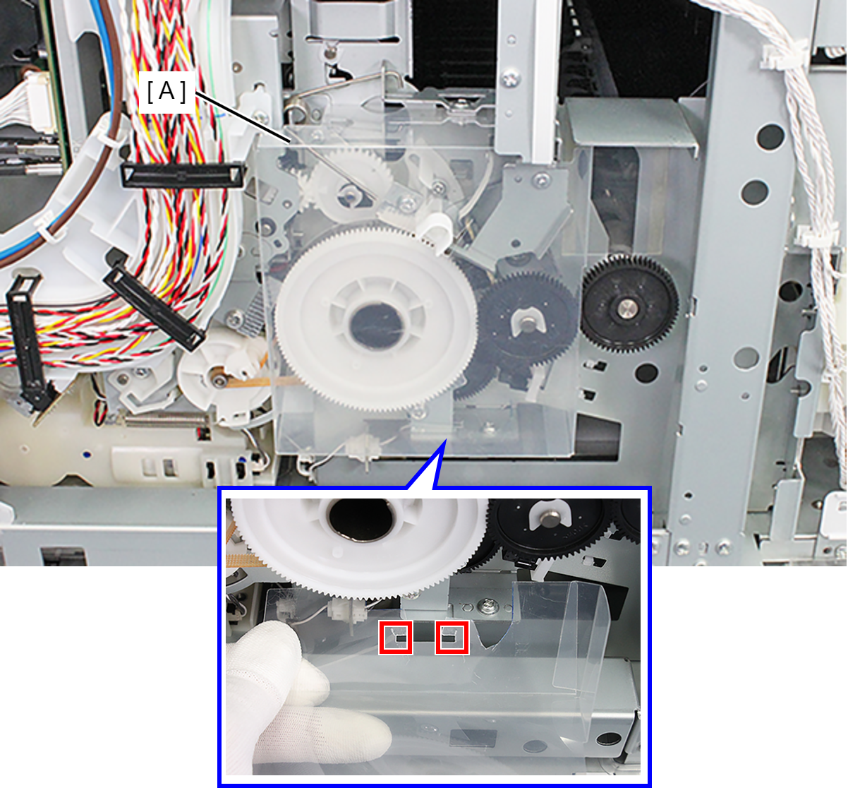
- Release the two hooks and remove the PF Scale Protection Material (A).
- Remove the screw, then remove the PF Brush Assy (A).
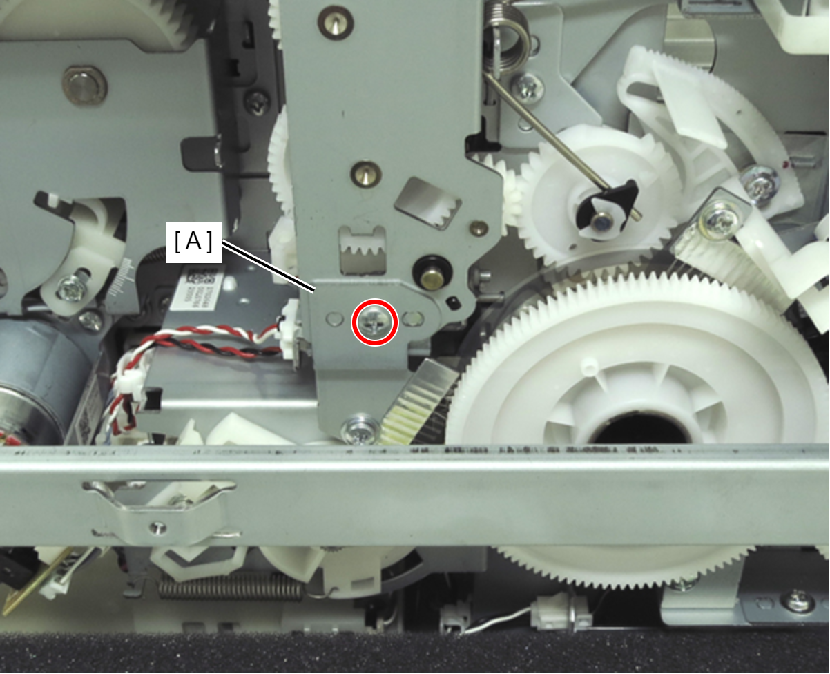
- :C.B.S-TITE-SCREW-3x6-F.ZN-3C
- Remove the two screws, then remove the APG Drive Unit.
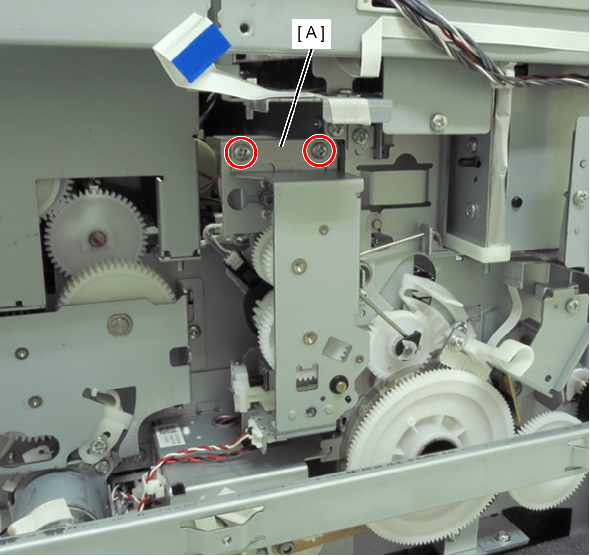
- : C.B.S-TITE-SCREW-3x6-F.ZN-3C
- Disconnect the cable (B) from the connector (A) of the sensor.
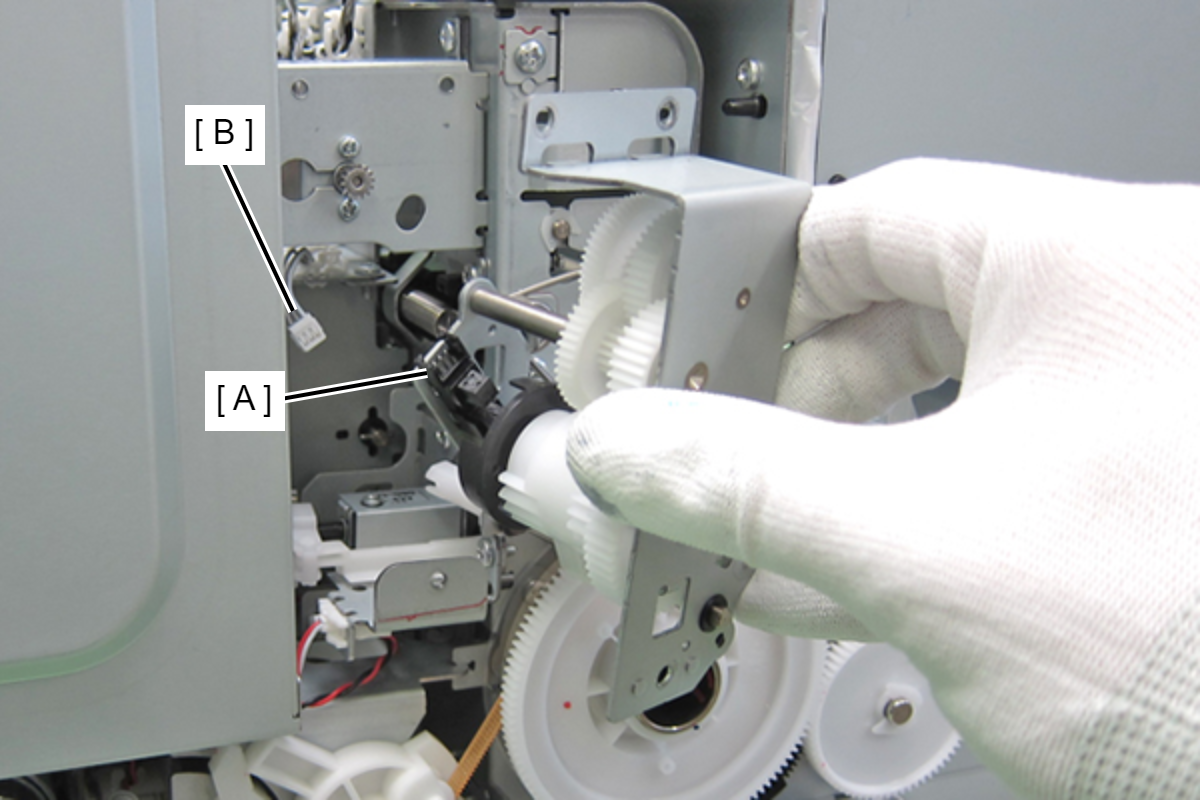 Assembly / 組み立て
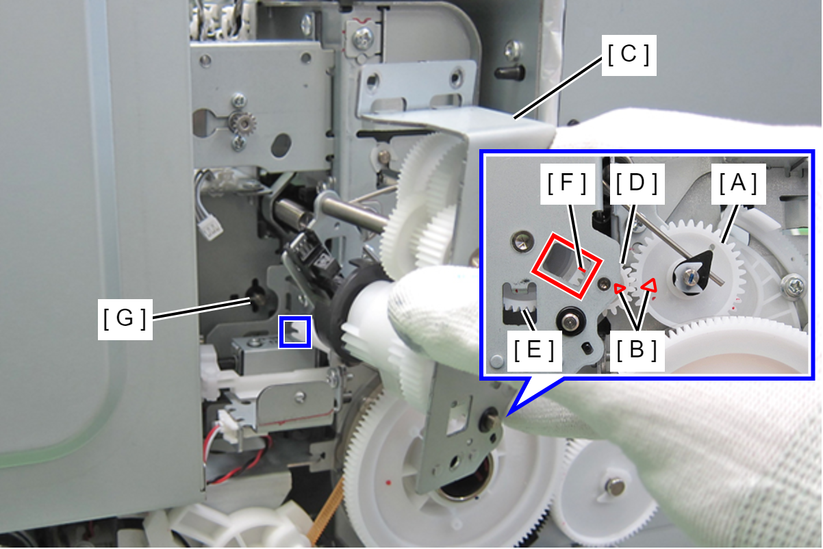
- Align the triangle mark (B) on the left APG cam (A) with the triangle mark (B) on the spur gear 14.4 (D) on the APG Drive Assy (C). At this point, make sure the mark (F) on the combination gear (E) can be seen through the hole on the APG Drive Assy (C).
- Insert the pin on the upper paper guide (G) into the groove on the release shaft holder of the APG Drive Unit.
- Release the four hooks and remove the APG Phase Sensor (A).
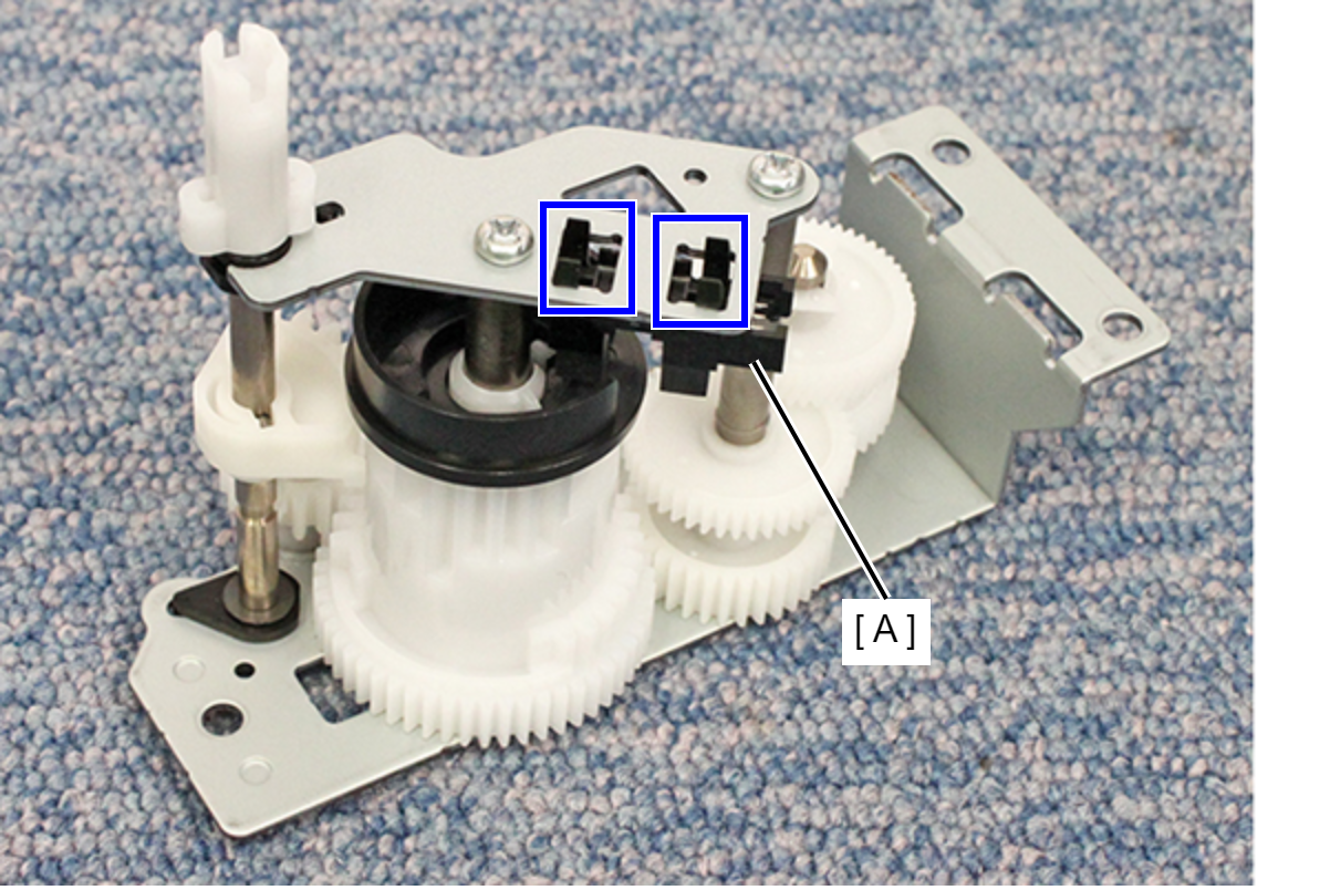
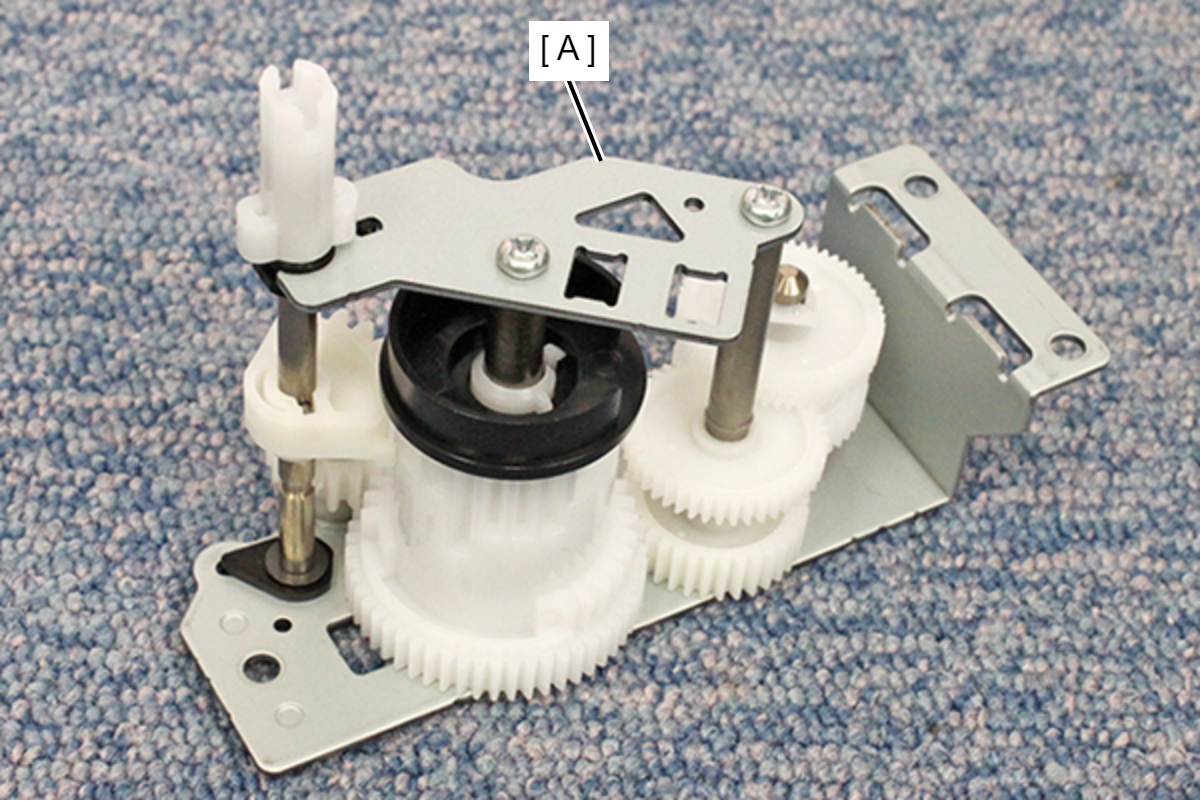
- Remove the APG Drive Assy (A).
| Adjustment / 調整 |
After replacing this part, you need to run the menu from the service support mode. (If you ran the Before-replacement menu before replacing the part, it will start automatically when you turn the power on.) |