
Paper Guide Upper Center Right
 Adjustment / 調整 Adjustment / 調整 |
When replacing this part, you need to run the menu from the service support mode before replacing it. |
- Remove the two screws.
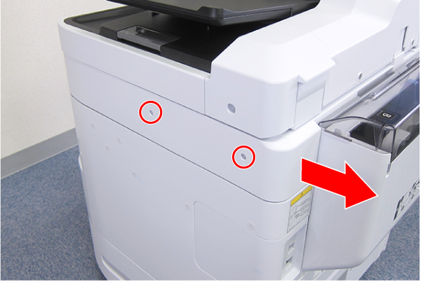
 : C.B.S-TITE-SCREW-3x8-F.ZN-3C
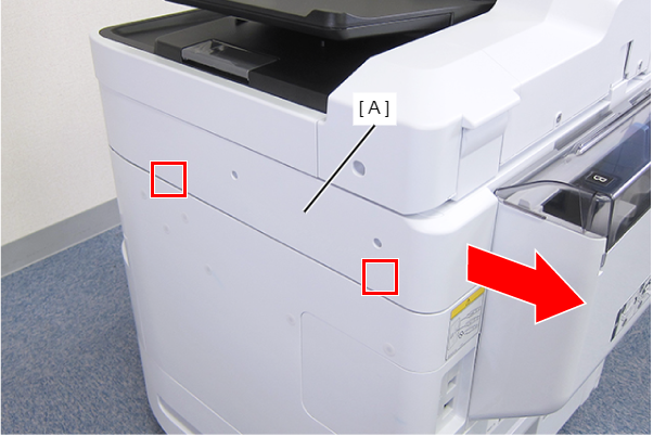
- Disengage the two hooks by sliding the Right SC Cover (A) toward the rear of the product, then remove it.
- Remove the screw.
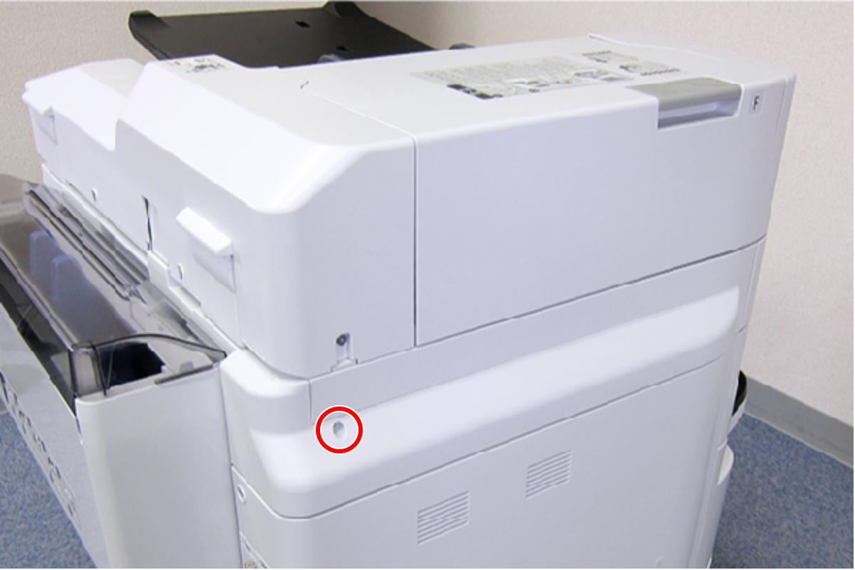
- : C.B.S-TITE-SCREW-3x8-F.ZN-3C
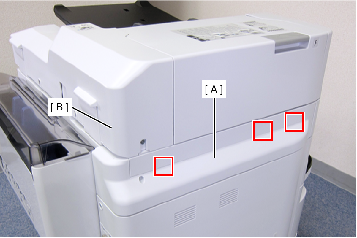
- Slide the Left SC Cover (A) toward the rear of the product to disengage the tab.
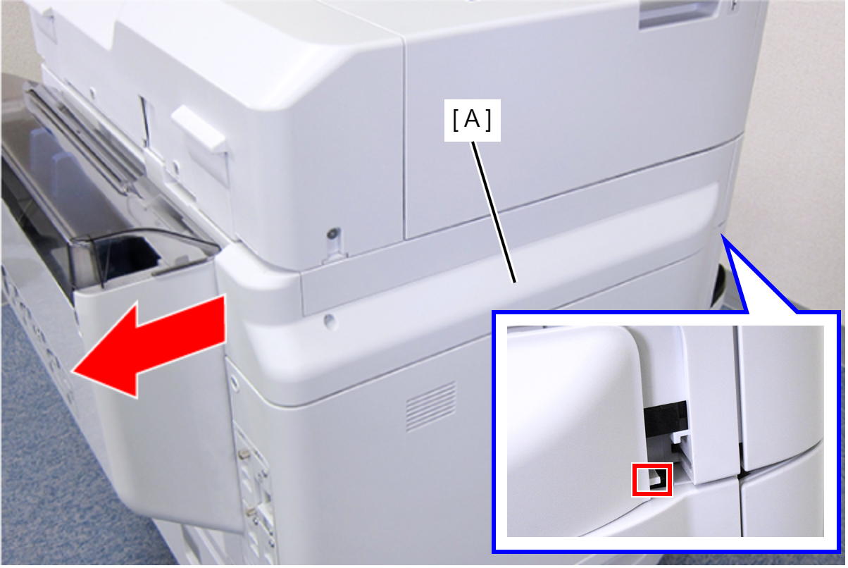
- Disengage the three tabs by inserting a flathead screwdriver into the gap between the Left SC Cover (A) and the ADF Unit (B), and then remove the Left SC Cover (A).
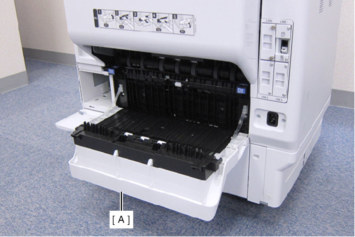
- Open the Duplex Print Cover (A).
- Remove the two screws, then remove the Connector Cover (A).
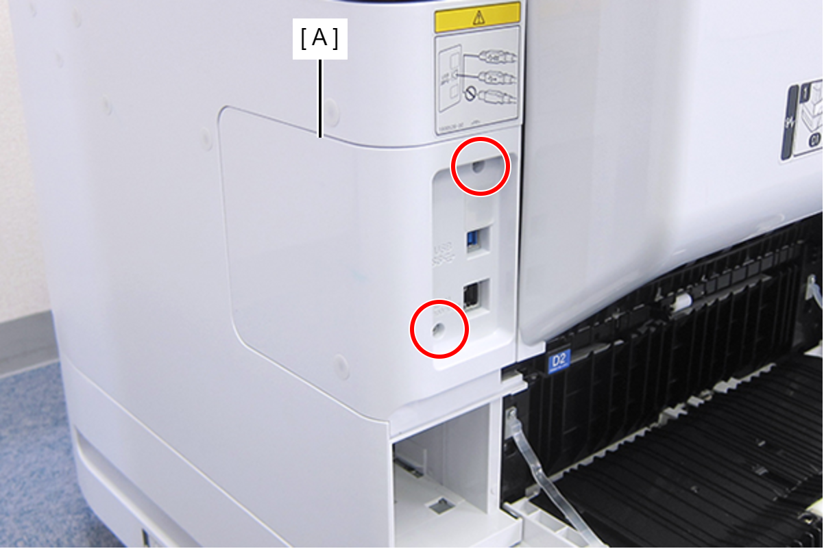
- : C.B.S-TITE-SCREW-3x8-F.ZN-3C
- Remove the two screws, then remove the Right Housing Assy (A) toward the rear of the product.
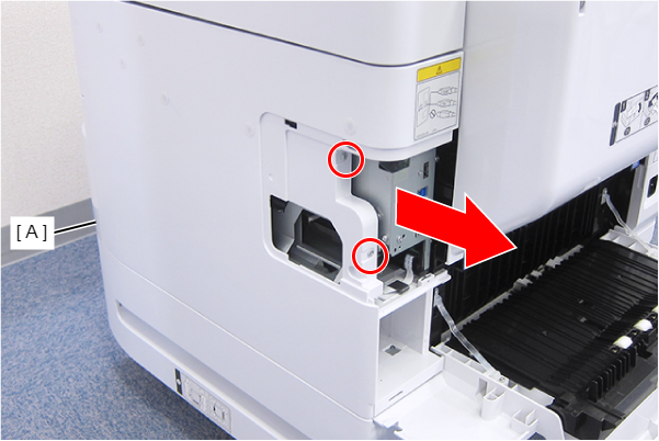
- : C.B.S-TITE-SCREW-3x8-F.ZN-3C
- Remove the three screws, then remove the Left Housing Assy (A) toward the rear of the product.
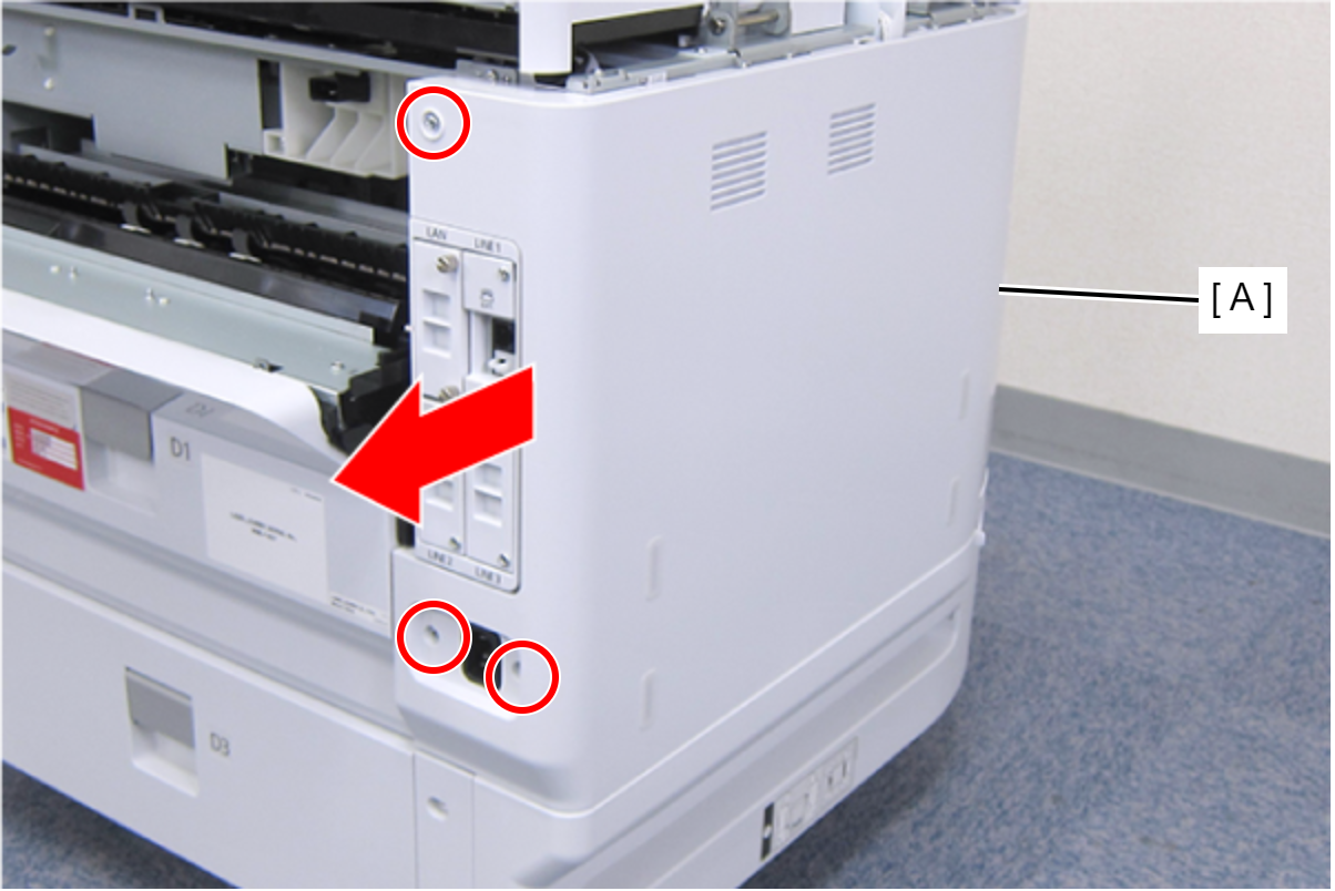
- : C.B.S-TITE-SCREW-3x8-F.ZN-3C
- Remove the two screws.
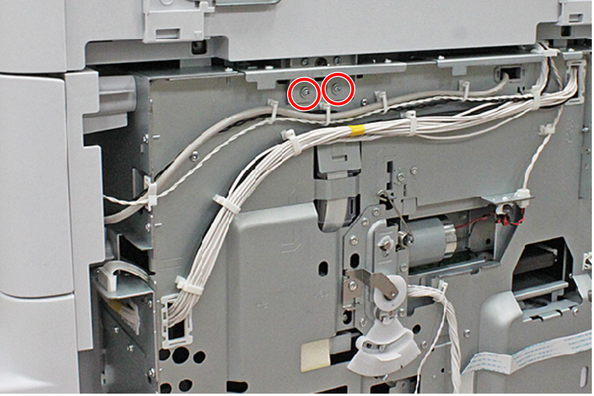
- : C.C.S-TITE-3x6-F.ZN-3C
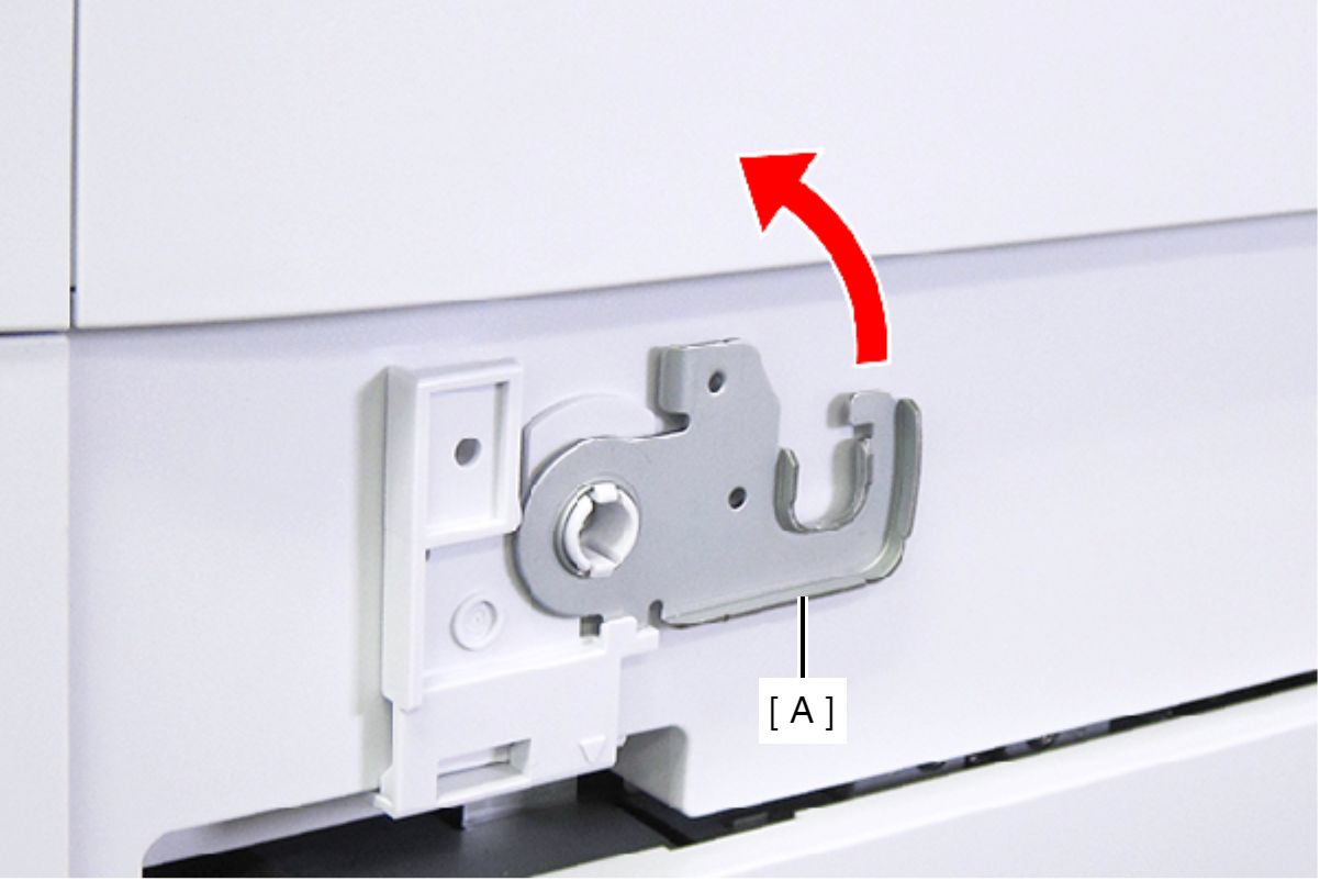
- Raise the ADF Stopper (A) to lock the ADF Unit.
- Secure the ADF Stopper with one of the screws you removed at step 1.
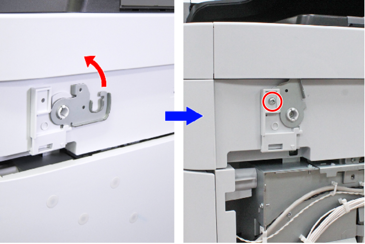
- : C.C.S-TITE-3x6-F.ZN-3C
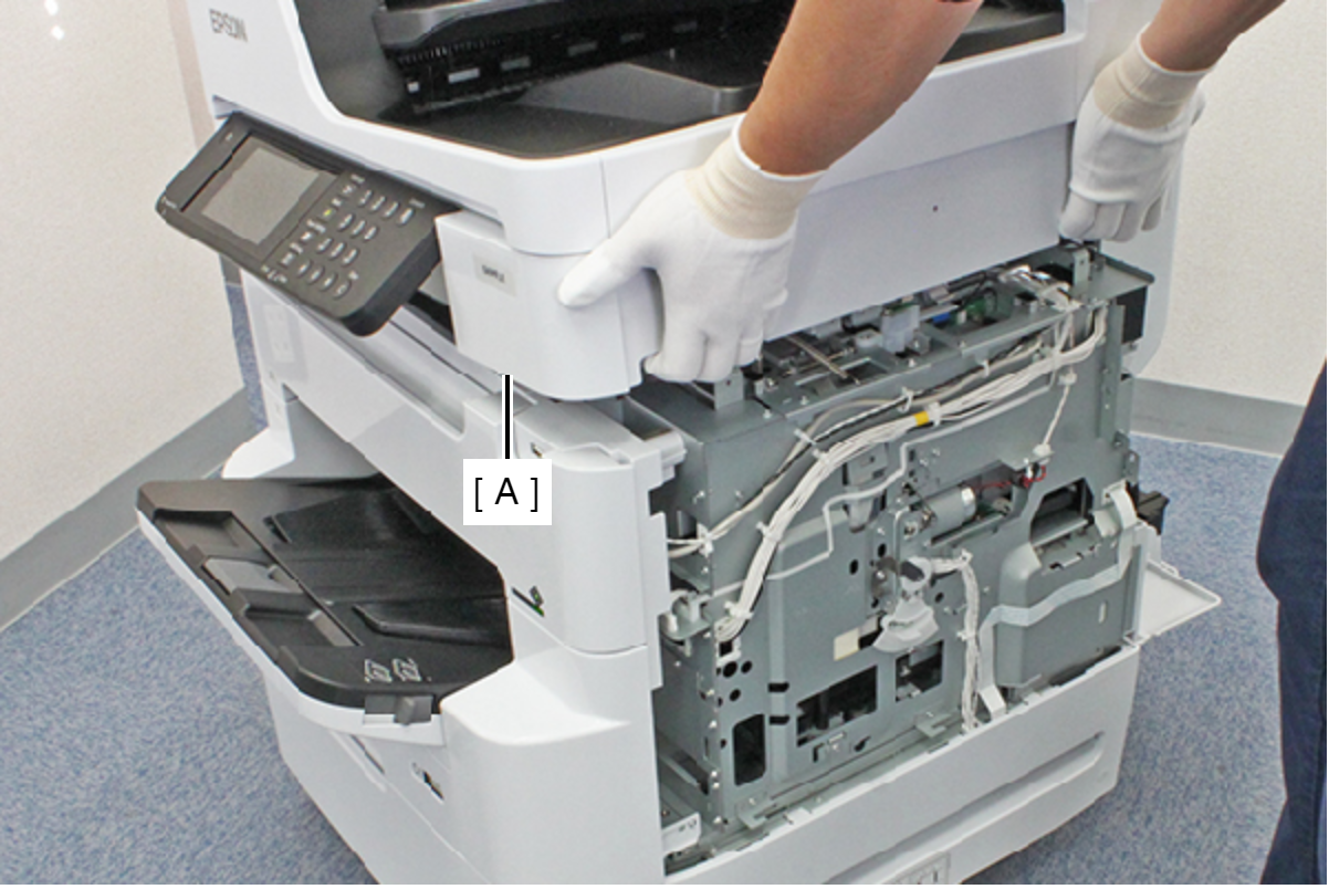
- Hold the ADF/SCN Unit (A) with both hands as shown above, and open the ADF/SCN Unit (A).
- Open the ADF/SCN Unit (A) and extend the support stand (B) as far as it goes, then support theADF/SCN Unit (A) with the support stand.
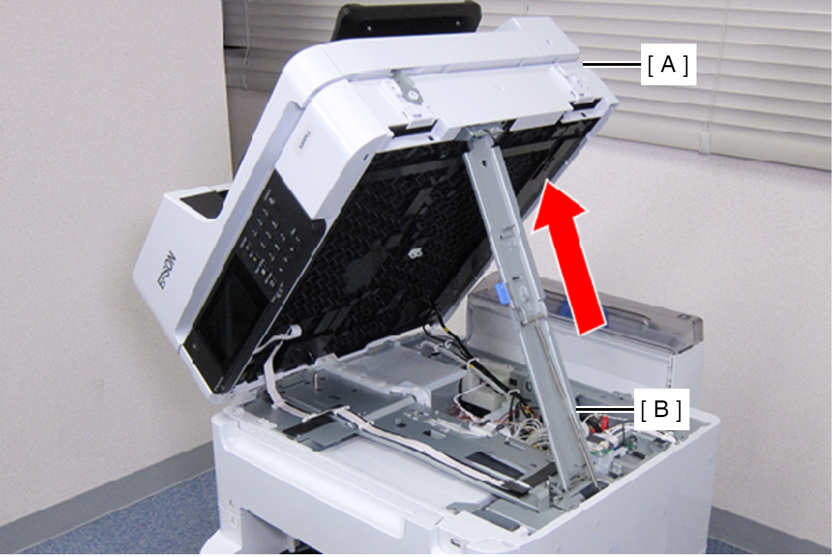
 Caution / 注意
Make sure that the extended support stand is fixed with the two hooks, and the two triangle marks face to each other.
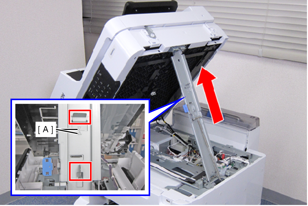
 Check Point / チェックポイント
When closing the ADF/SCN Unit, hold down the switch on the support stand and raise the ADF/SCN Unit in the direction of the arrow to disengage the two hooks, then fold the support stand.
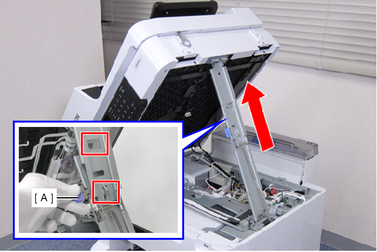
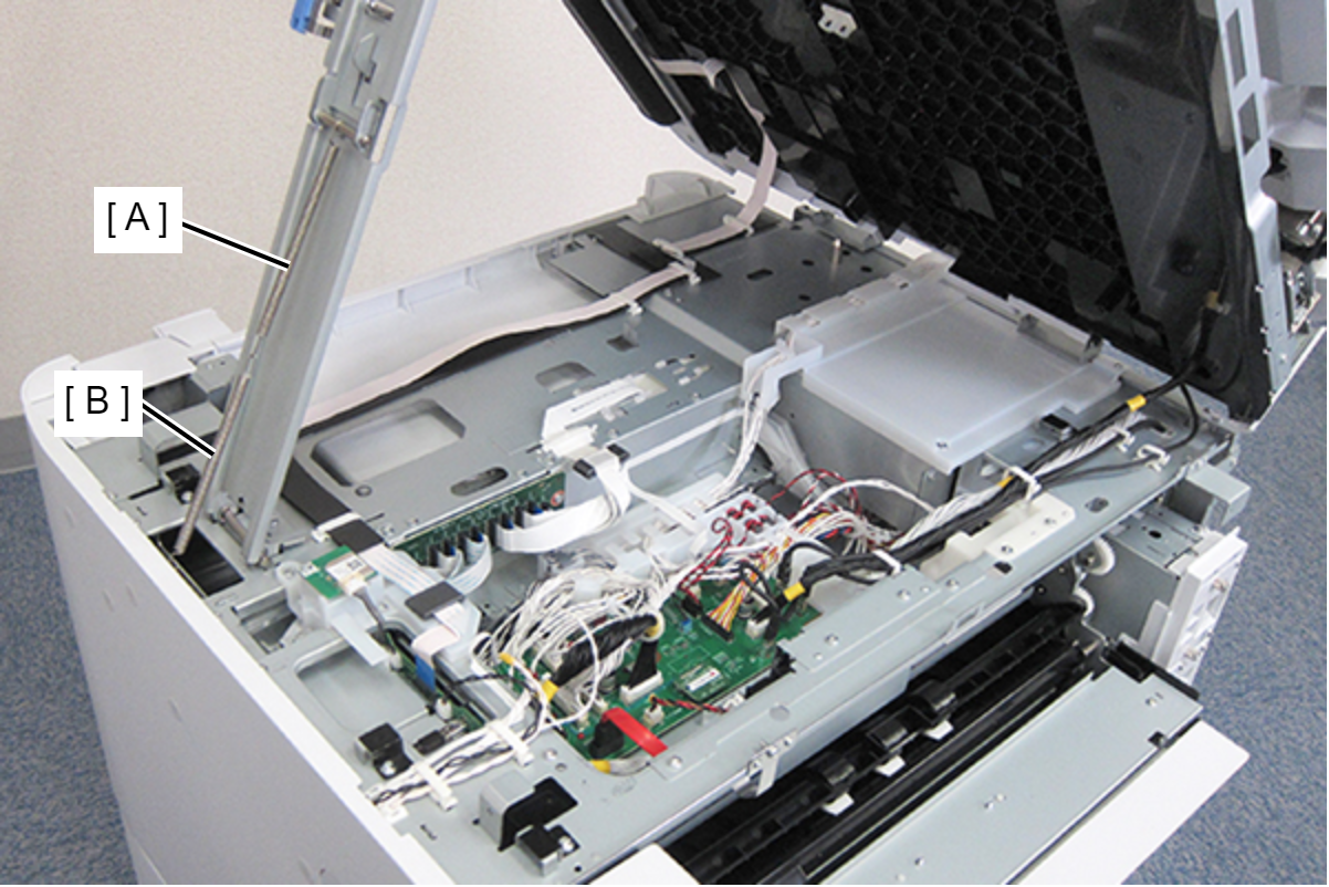
- Separate the upper spring (A) and lower spring (B).
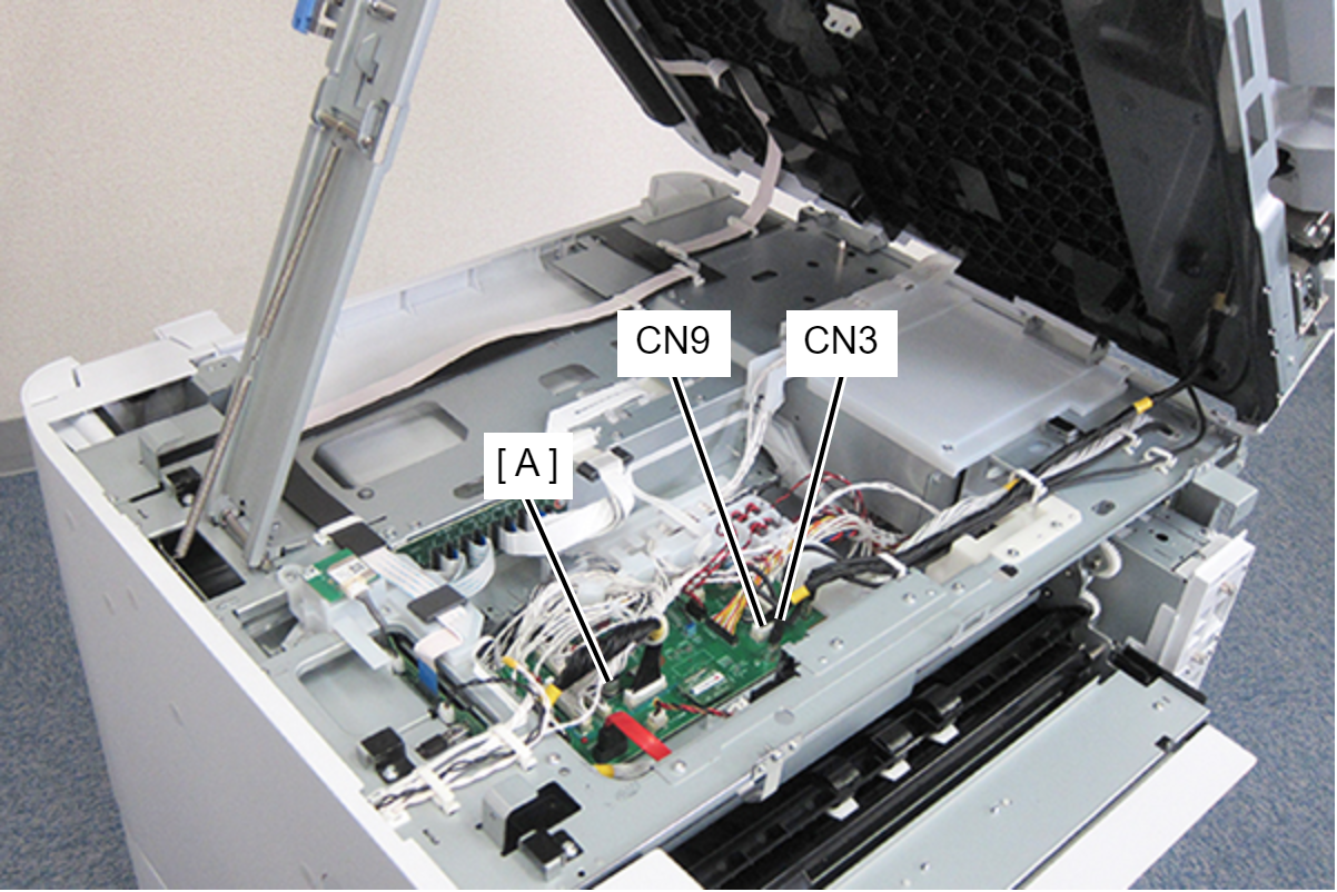
- Disconnect the following cables from the PCB Mechanism Relay Board (A).
- Cable (USB) (CN3)
- Cable (CN9) (With hook)
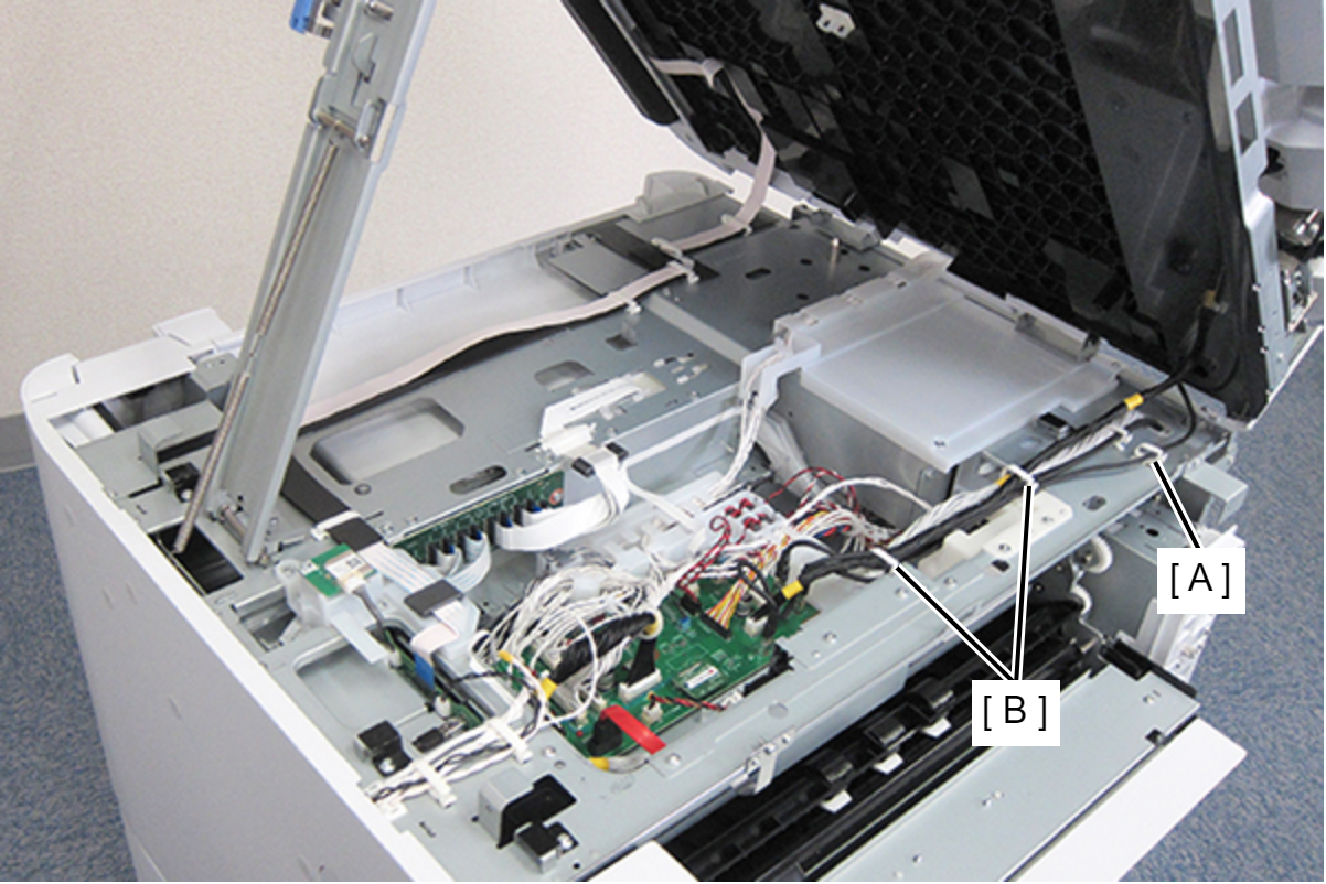
- Release the two cable from the three clamps (A, B). (Only the cable (USB) is routed through the clamp (A).)
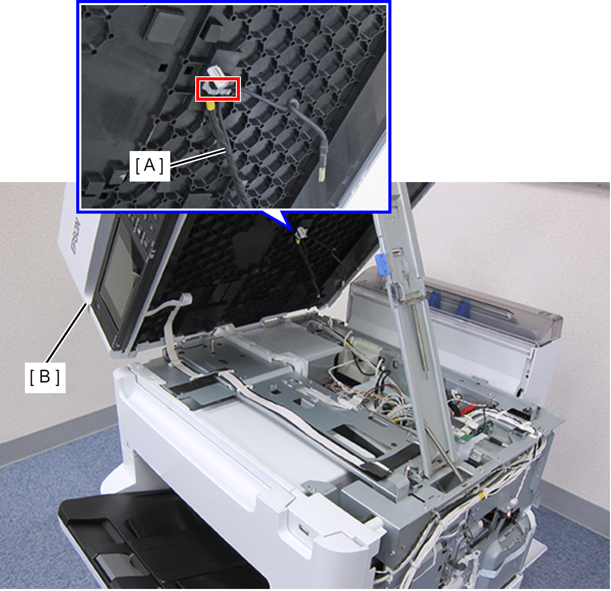
- Secure the two cables (A) with the two hooks on the ADF/SCN Unit (B).
- Disconnect the Panel FFC (A) from CN302 connector on the Main Board.
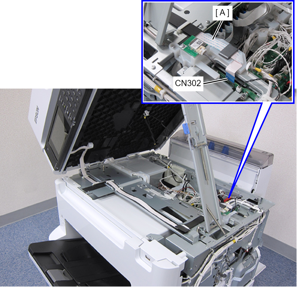
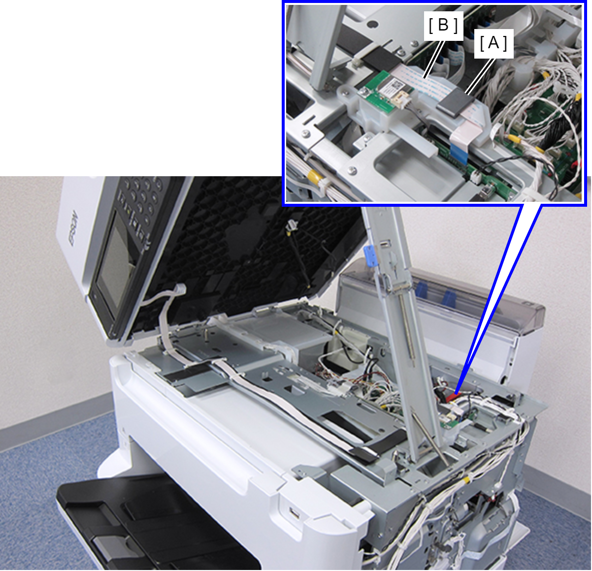
- Remove the Panel FFC (B) from the ferrite core (A).
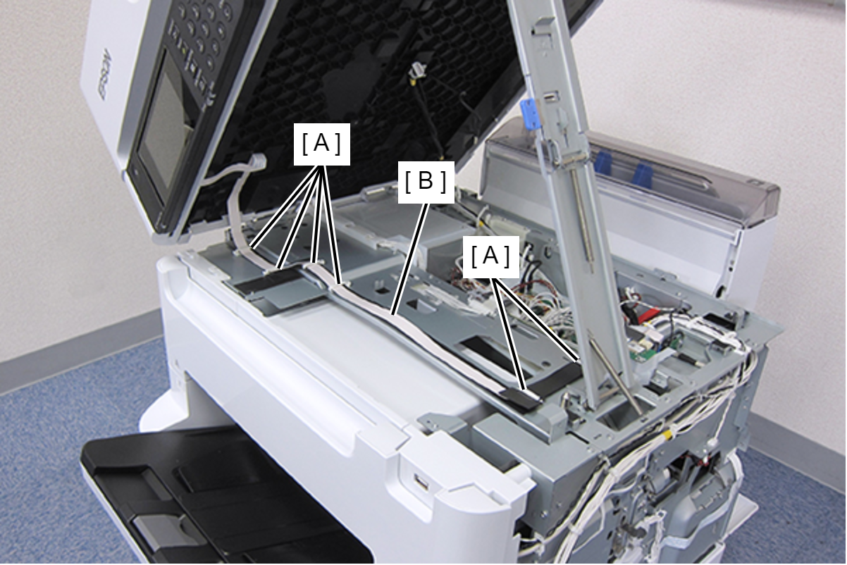
- Release the Panel FFC (B) from the six clamps (A).
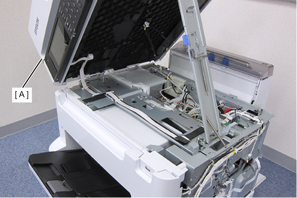
- Close the ADF/SCN Unit (A).
 Assembly / 組み立て
When opening the ADF/SCN Unit with the upper and lower springs separated, carefully open it because the support stand does not automatically extend.
- Remove the six screws.
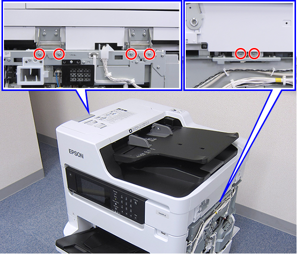
- : C.B.S-TITE-SCREW-3x8-F.ZN-3C
Check Point / チェックポイントThe screws to be removed have a triangle mark.
- Pull the ADF/SCN Unit (A) upward to remove it.
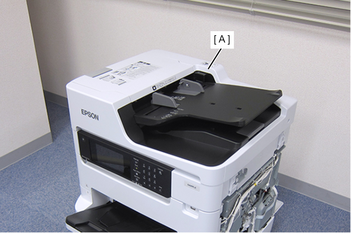
 WARNING / 警告
After replacing the ADF/SCN Unit, a fatal error (1000050) may occur due to a difference in version between the printer firmware and the scanner firmware.
Make sure to update the firmware after replacing the ADF/SCN Unit. - Remove the cable/FFC from all connectors of the PCB Mechanism Relay Board (A).
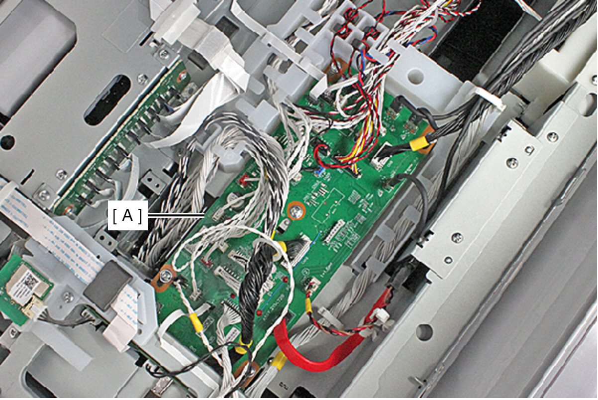 Check Point / チェックポイント
PCB Mechanism Relay Board Connectors: Cables connected to CN7, CN9, CN10, CN26, CN37, and CN38 are fastened by the connector lock.
- Release all cable/FFC routed in the Relay Harness Cover (A).
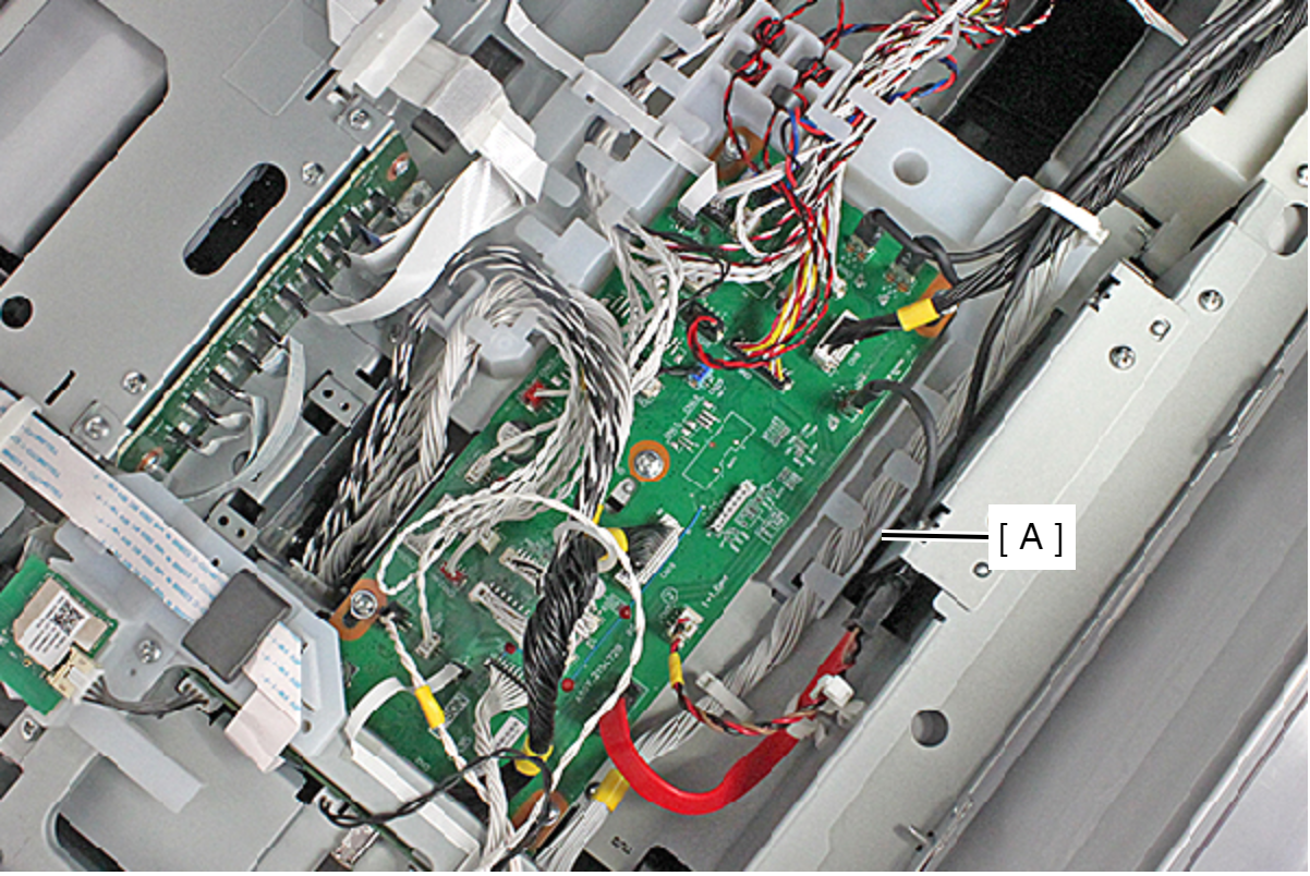
- Remove the screw, and remove the Relay Harness Cover (A).
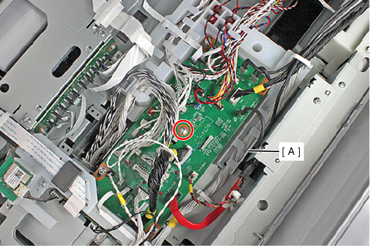
- : C.B.S-TITE-P4-SCREW-3x8-F.ZN-3C
Assembly / 組み立てWhen routing the cable/FFC to the Relay Harness Cover, refer to the photo above.
- Remove the five screws fastening the PCB Mechanism Relay Board (A).
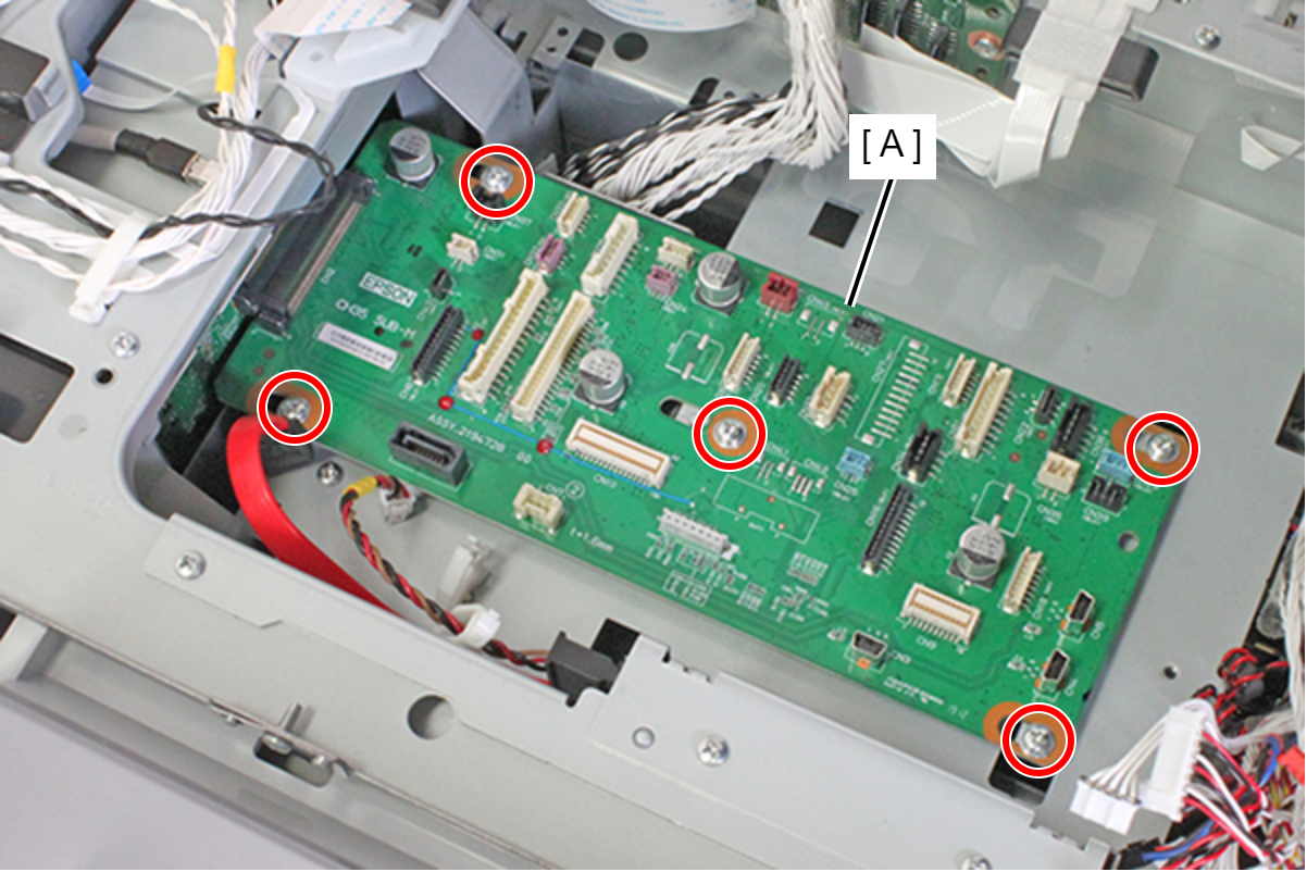
- : C.B.S-TITE-P4-SCREW-3x8-F.ZN-3C
- Slide the PCB Mechanism Relay Board (A) in the direction of the arrow to remove the connector (CN2) connecting to the Main Board (B) and remove the PCB Mechanism Relay Board.
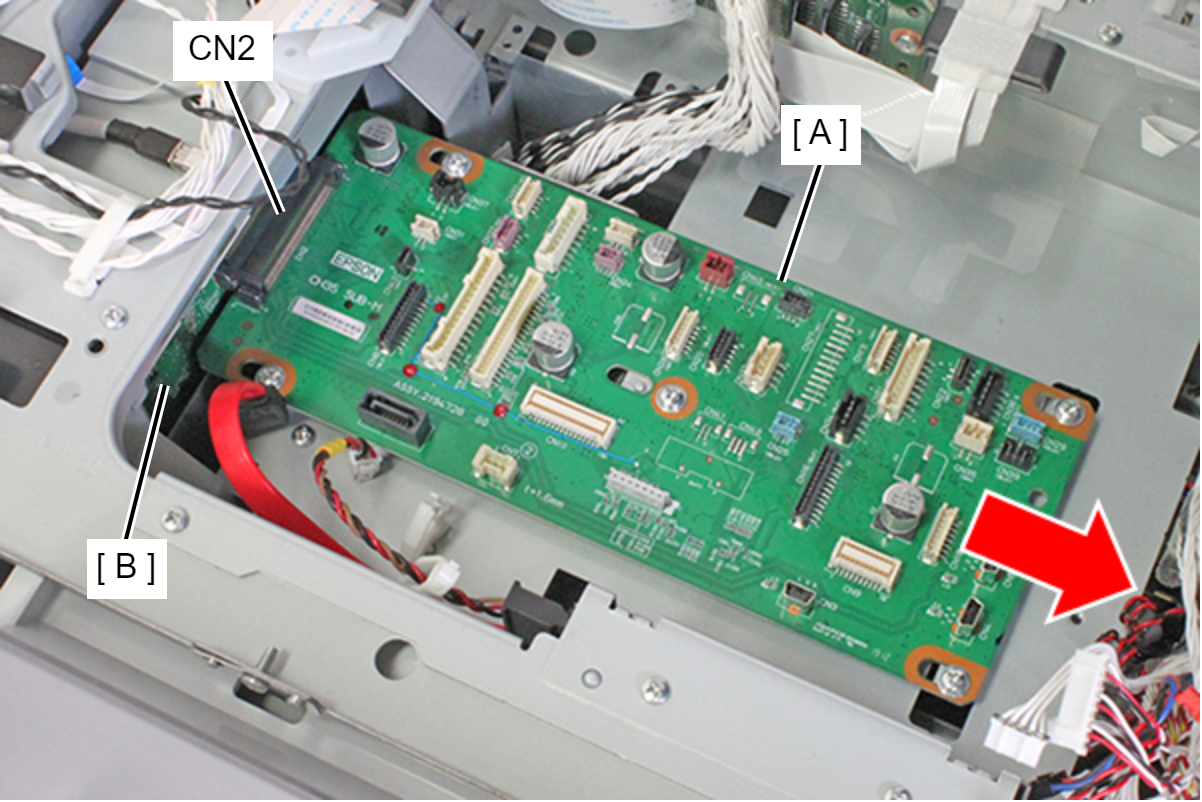
- Release each cable from the two clamps (A).
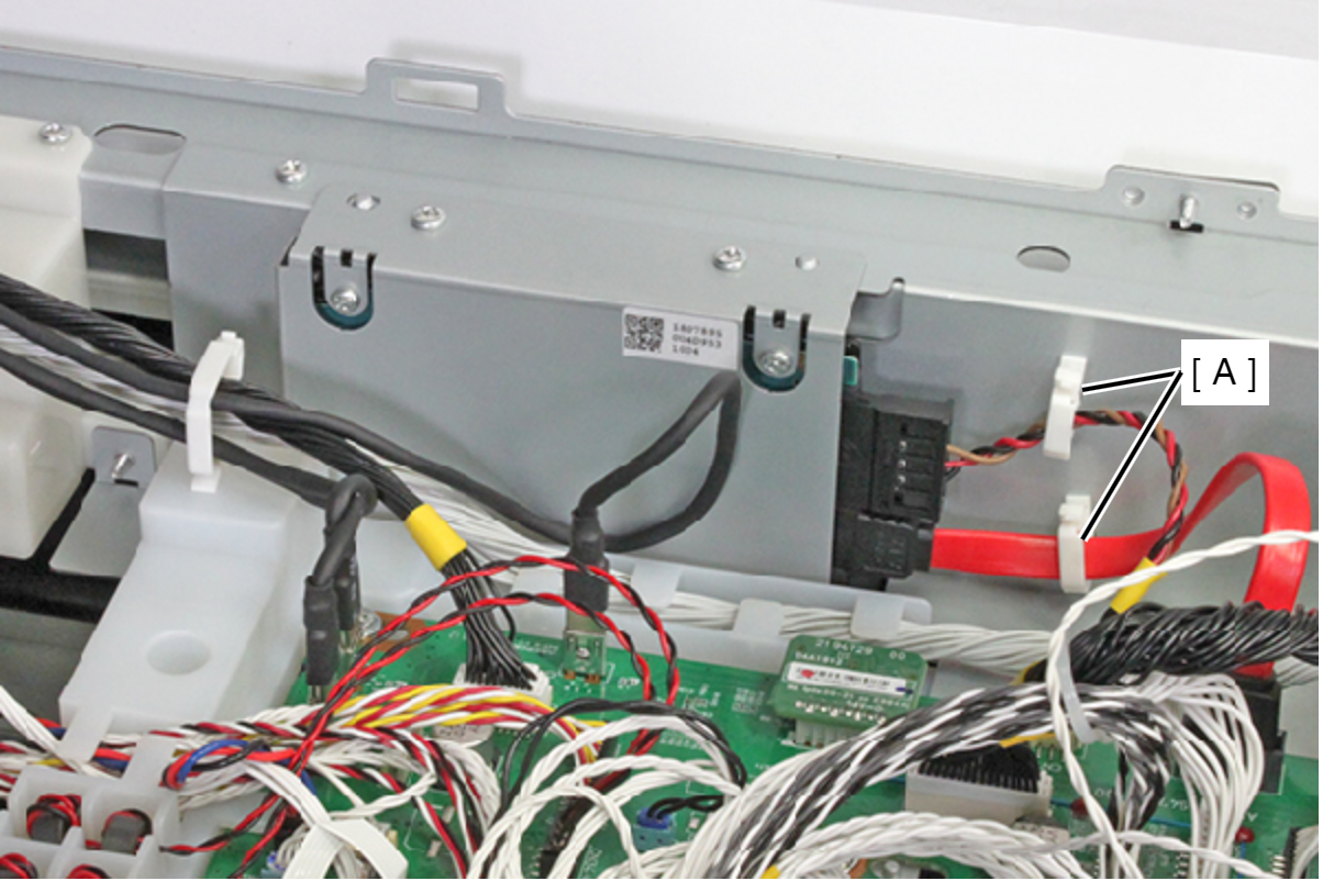
- Remove the two cables from the connector of the SSD (A).
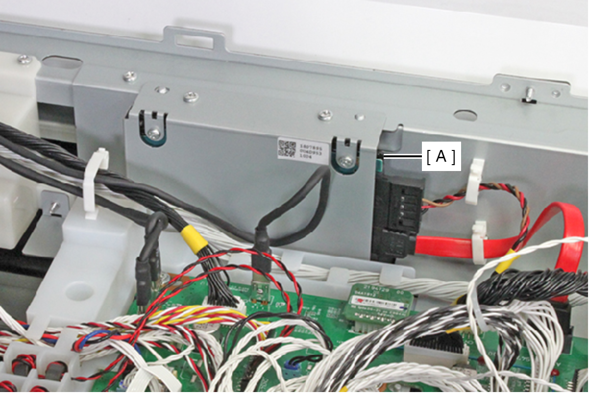
- Remove the three screws, and remove the SSD Assy (A).
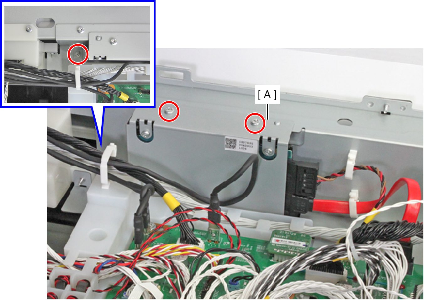
- : C.B.S-TITE-SCREW-3x8-F.ZN-3C
- Remove the two screws, then remove the Rear ASF Unit (A).
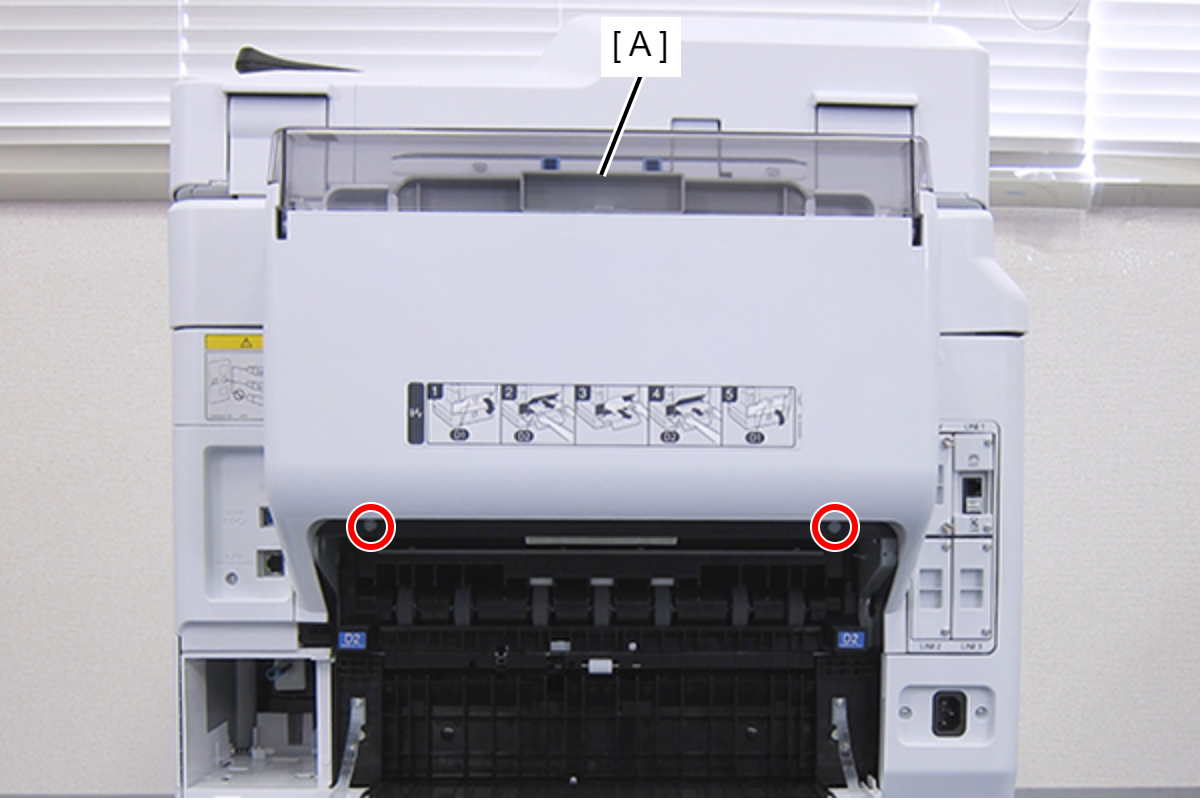
- : C.SHOULDER S-TITE,3X5
- Release the cable from the clamp (A) and remove it from the connector (CN503 (with hook)) (B) of the Main Board.
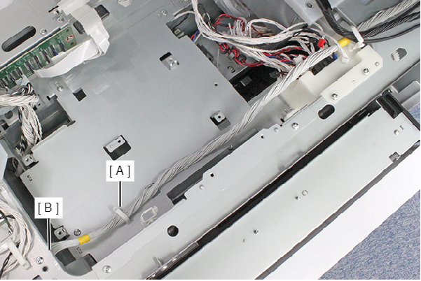
- Remove the seven screws, and remove the PCB Mechanism Relay Board Mounting Plate (A).
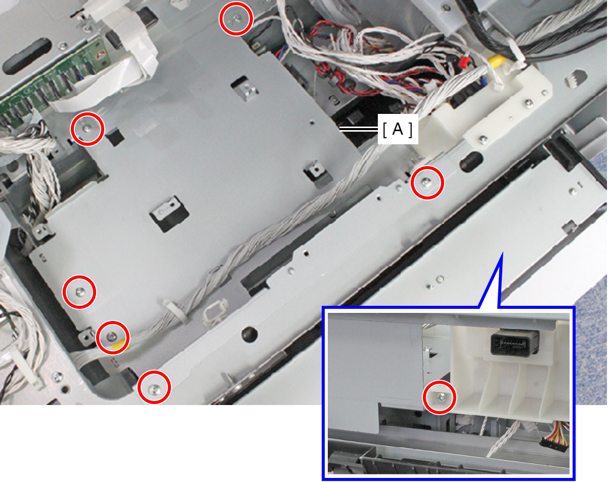
- : C.B.S-TITE-SCREW-3x8-F.ZN-3C
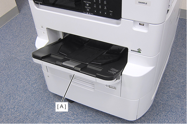
- Remove the Stacker Assy (A).
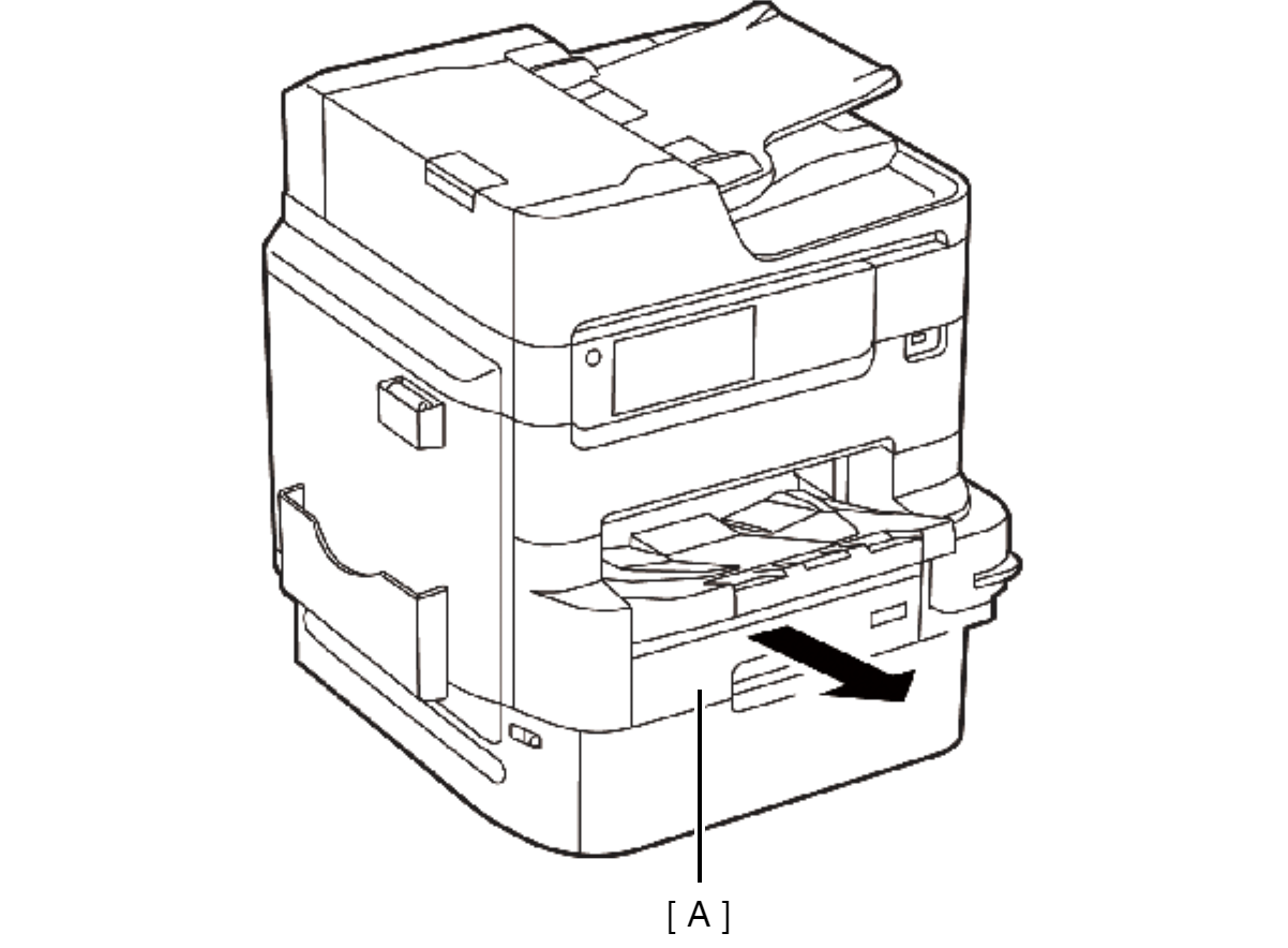
- Remove the Cassette Assy (A).
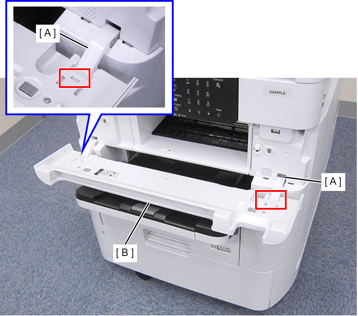
- Open the Front Cover Assy (A).
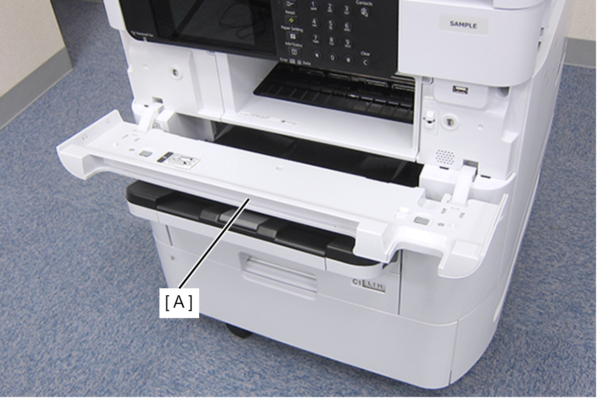
- While pressing the two hooks of the hinge (A), remove the Front Cover Assy (A) frontward.
- Remove the three screws fastening the Front Left Housing (A).
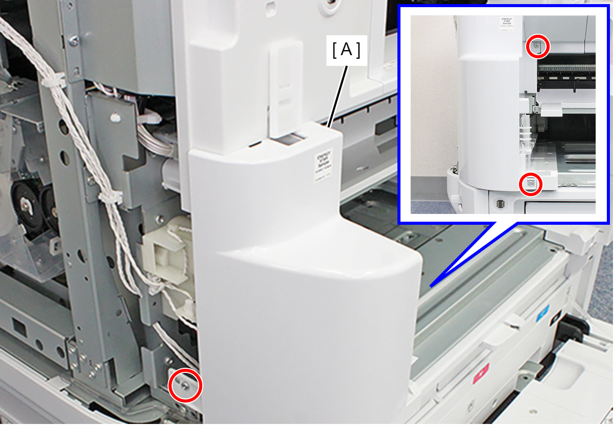
- : C.B.S-TITE-SCREW-3x8-F.ZN-3C
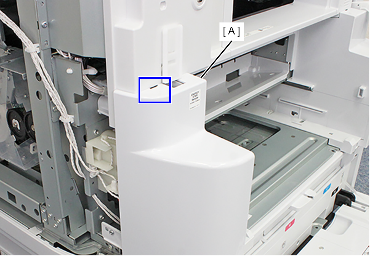
- Release the hook and remove the Front Left Housing (A).
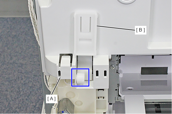
- Remove the Front Cover Hinge Left (B) from the Dowel on the Front Inner Housing Left (A).
- Remove the four screws, then remove the Front Inner Housing Center (A) frontward.
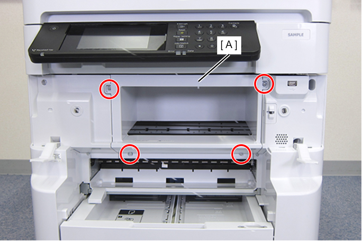
- : C.B.S-TITE-SCREW-3x8-F.ZN-3C
- Remove the two screws fastening the Front Inner Housing Left (A).
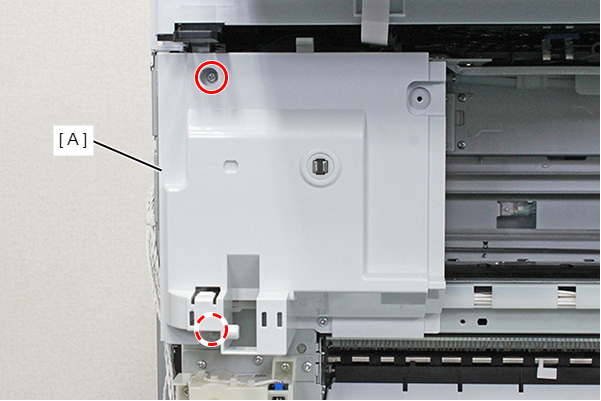
- : C.B.S-TITE-SCREW-3x8-F.ZN-3C
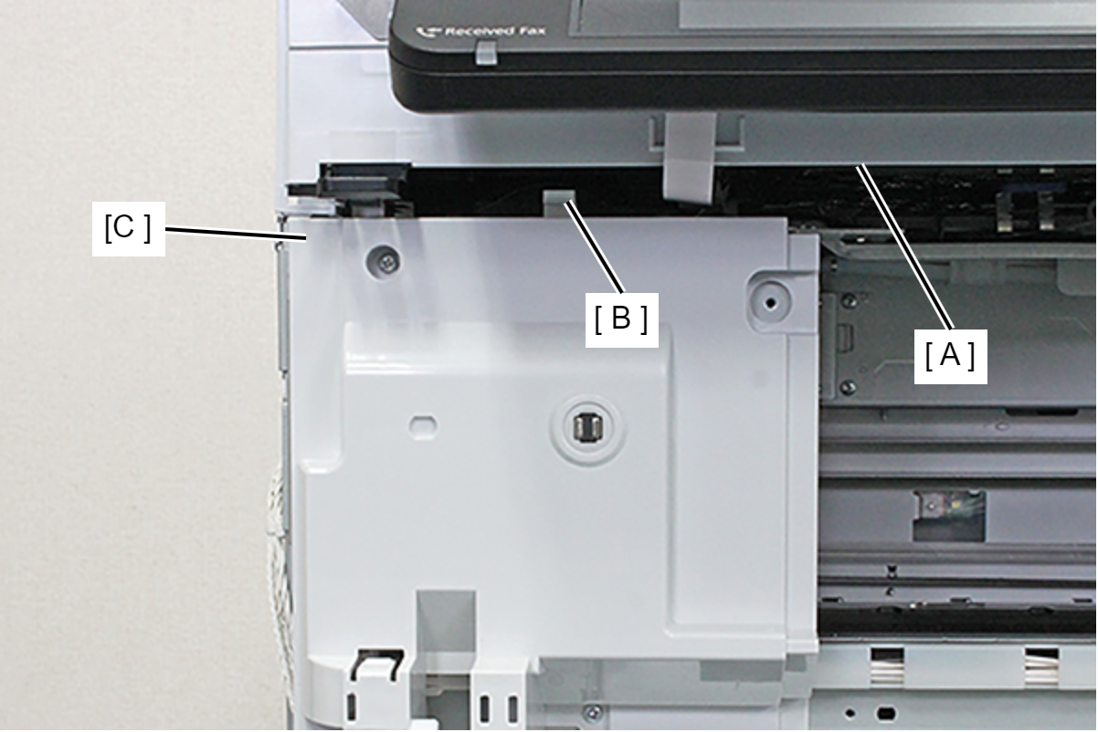
- Remove the Front Inner Housing Left (C) while releasing the place interfering (A) with the ADF/SCN Unit (A).
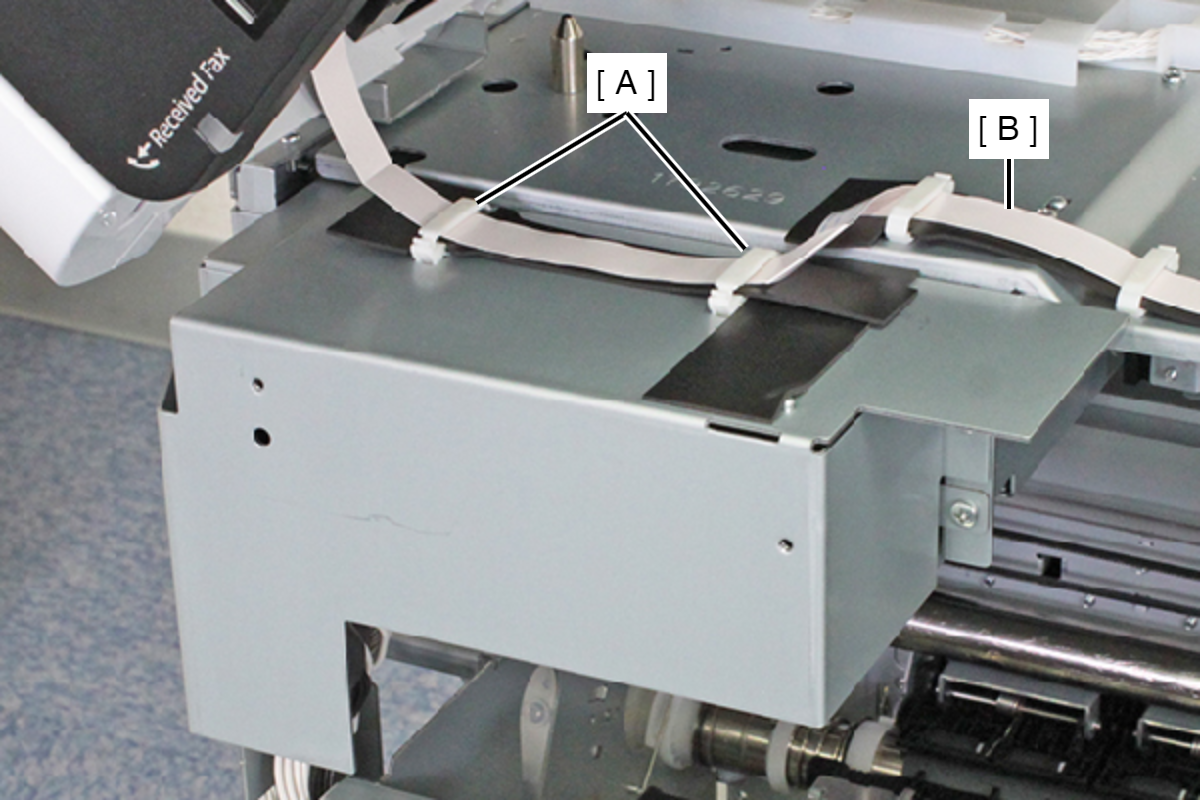
- Release the Panel FFC (B) from the two clamps (A).
- Remove the two screws and remove the Power Supply Unit Cover (A).
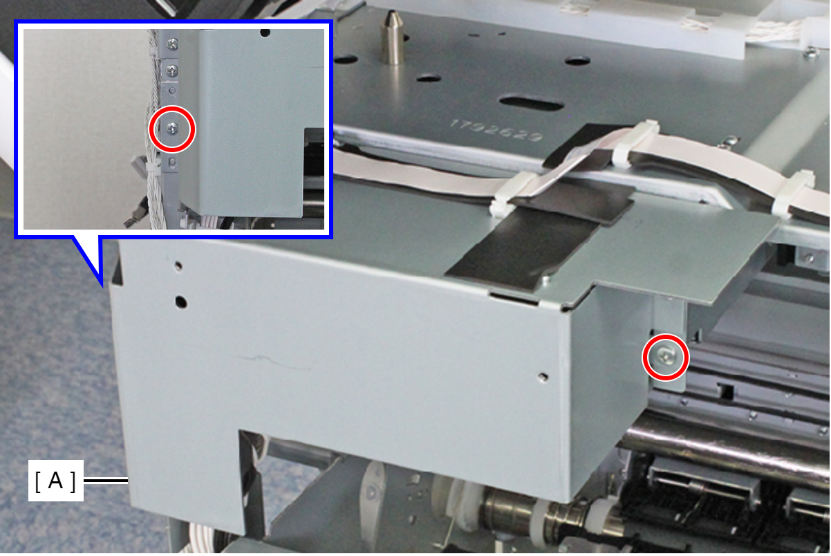
- : C.B.S-TITE-SCREW-3x8-F.ZN-3C
- Release the two cables from the two clamps (A).
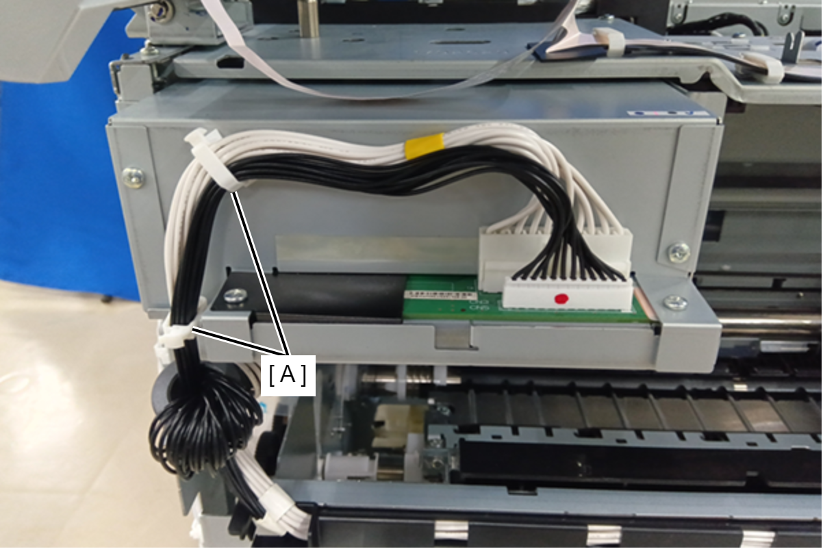
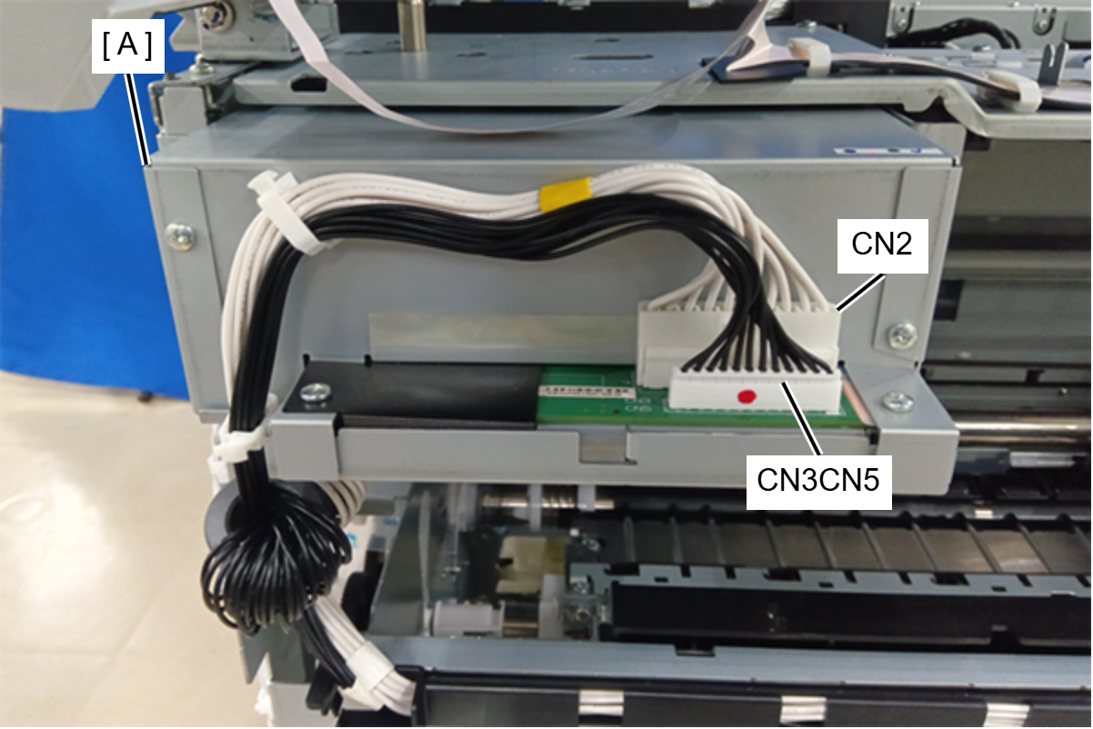
- Remove the cables from the connectors (CN2 (with hooks), CN3, CN5) of the Power Supply Unit.
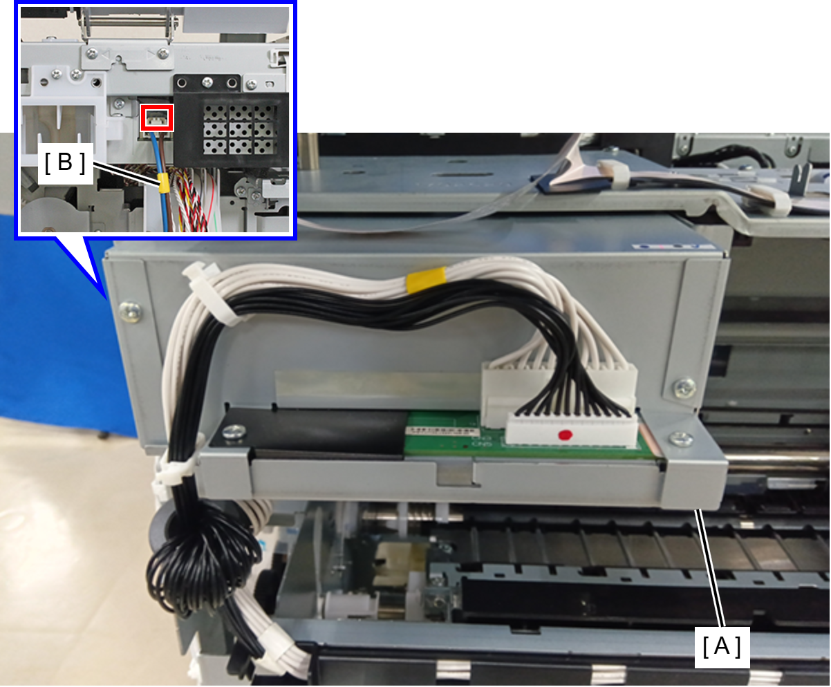
- Remove the Power Supply Unit Cable (B) from the Power Supply Unit (A) while releasing the hook.
- Remove the three screws and remove the Power Supply Unit (A).
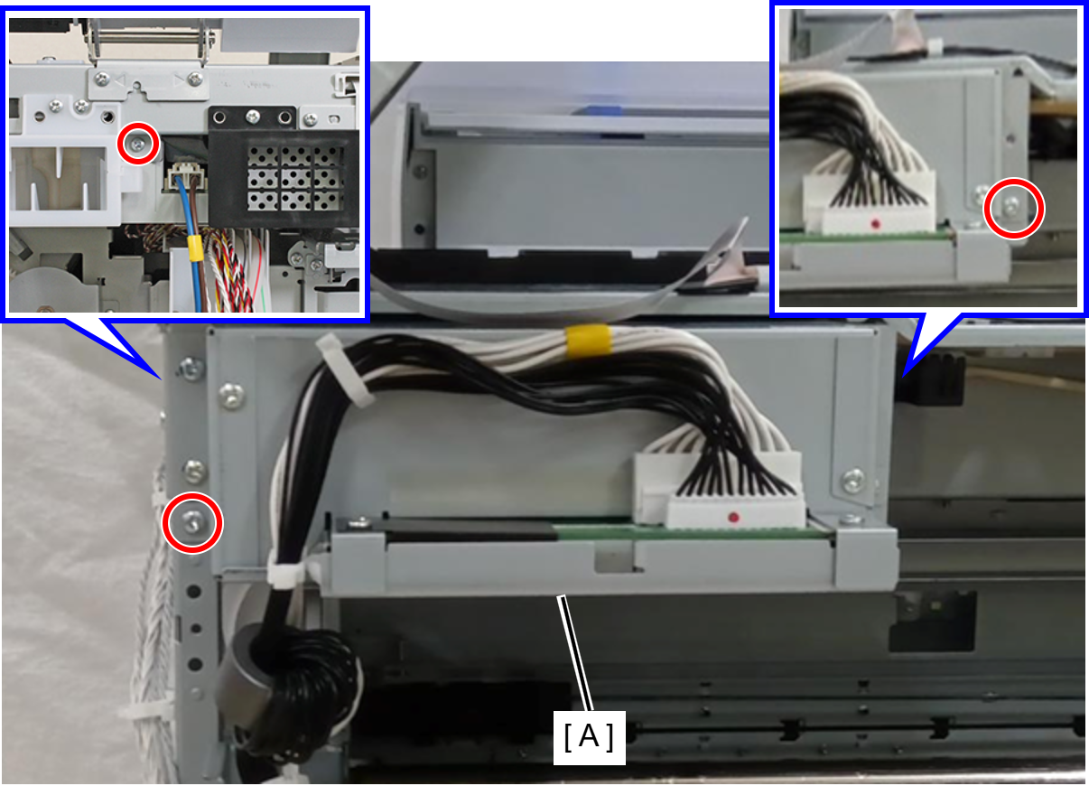
- : C.B.S-TITE-SCREW-3x8-F.ZN-3C
- Remove the two screws, and remove the I/F Housing Bracket (A).
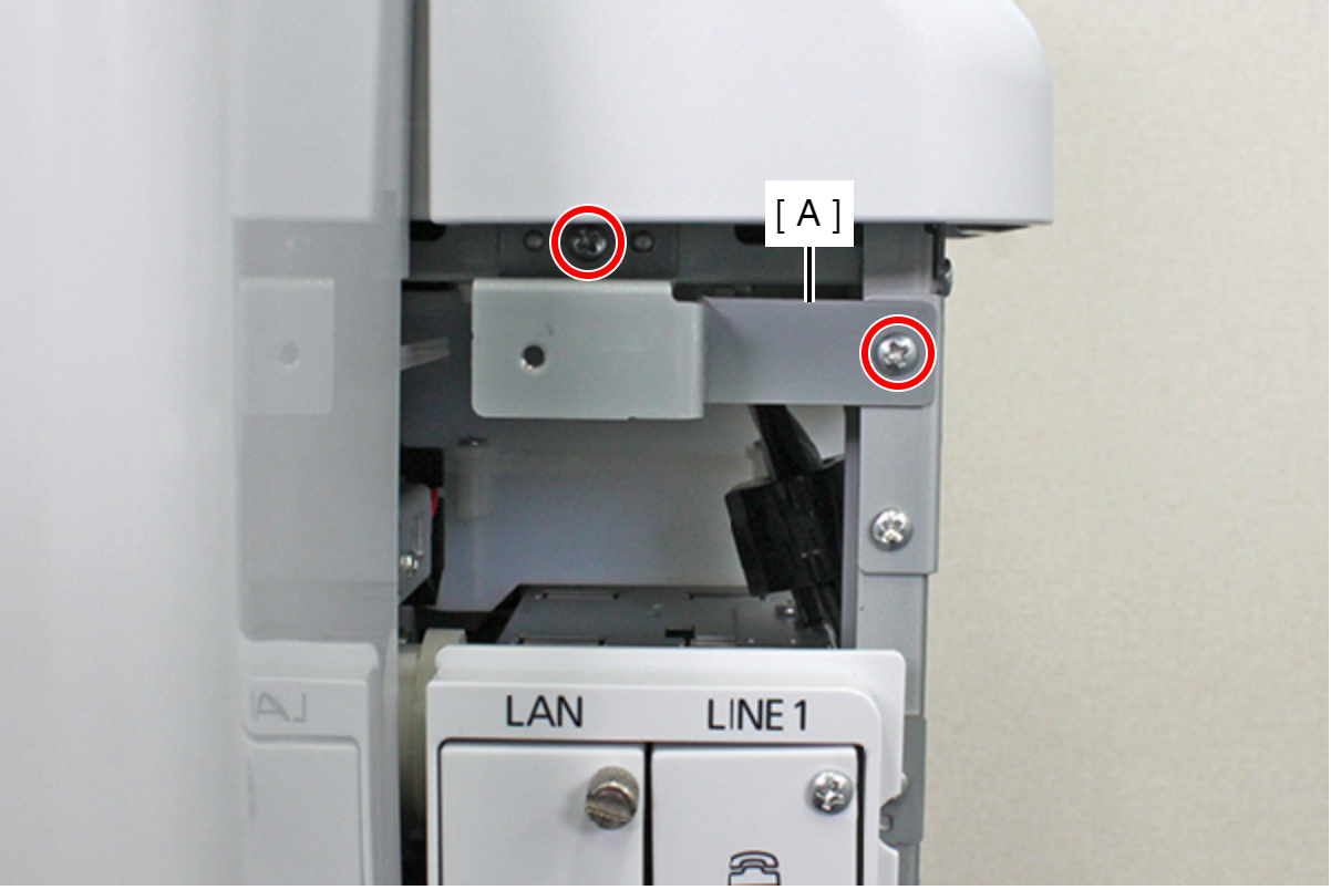
- : C.B.S-TITE-SCREW-3x8-F.ZN-3C
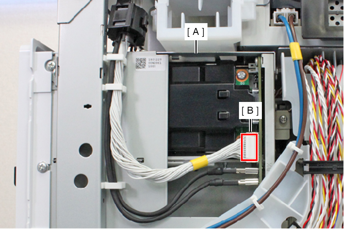
Remove the cable from the connector (CN7) (B) of the I/F Port Assy (A) while releasing the hook.
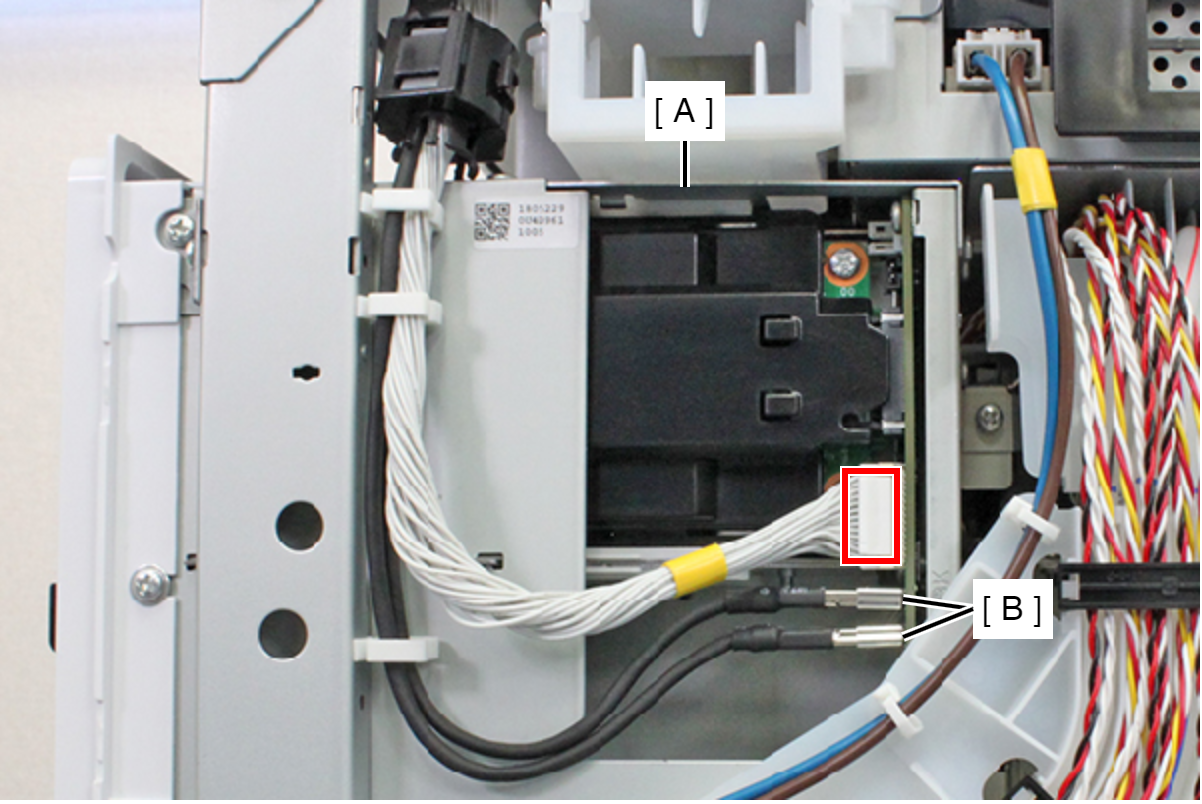
- Remove the cable from the connectors (CN5, CN6) (B) of the I/F Port Assy (A).
- Remove the four screws, and remove the I/F Port Assy (A).
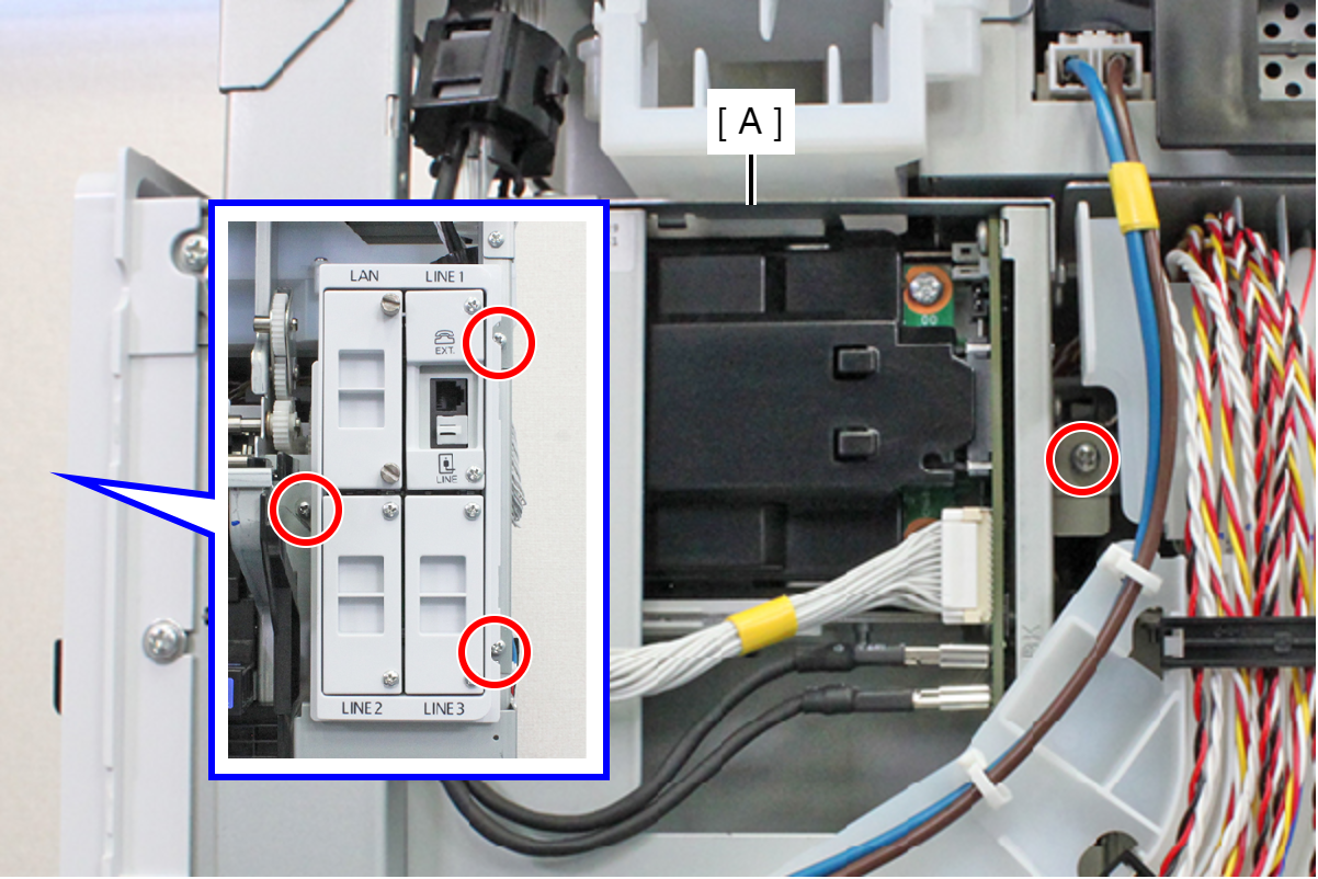
- : C.B.S-TITE-SCREW-3x8-F.ZN-3C
- Remove the screw, and retract the Tube Guide to the back face side.
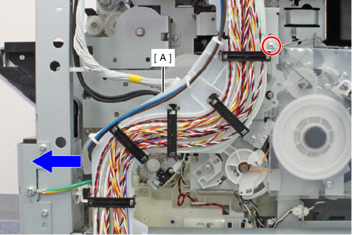
- : C.B.S-TITE-SCREW-3x8-F.ZN-3C
- Remove the hole from the screw feet (A) and pull out the folded portion (C) of the PF Scale Protection Material (B).
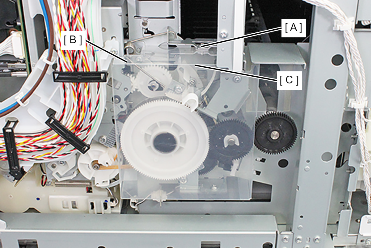
- Release the two hooks and remove the PF Scale Protection Material (A).
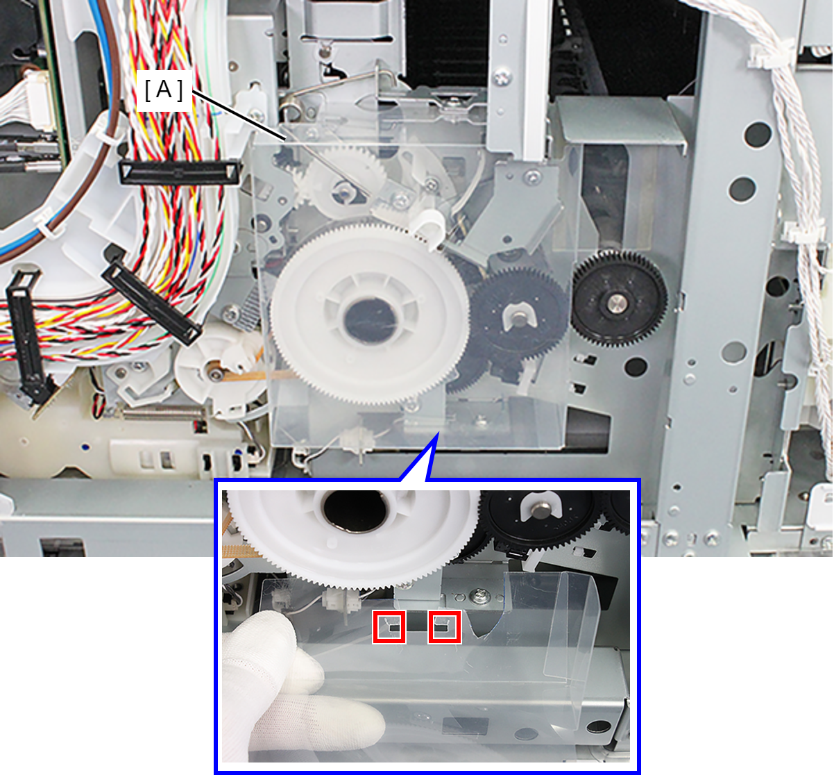
- Remove the screw, then remove the PF Brush Assy (A).
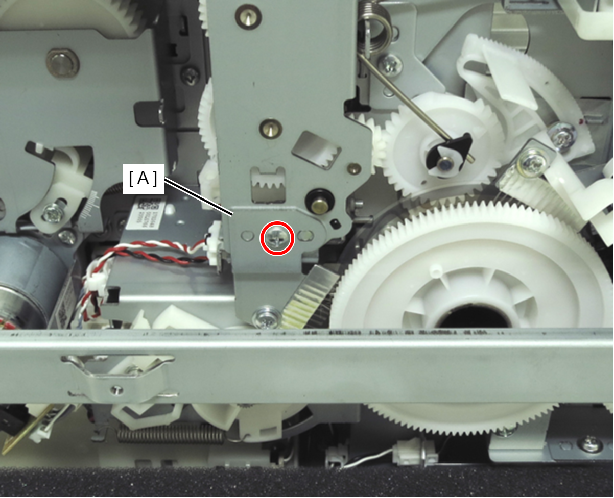
 :C.B.S-TITE-SCREW-3x6-F.ZN-3C
- Remove the APG Drive Assy (A).
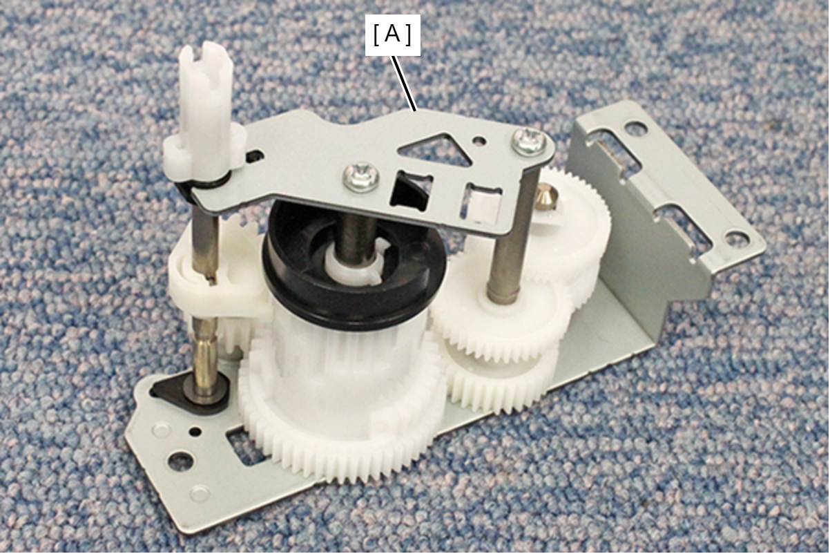
- Release the cable from the clamp (A).

- Remove the two screws, and remove the Rear ASF Relay Connector Assy (A). (If the PCB Mechanism Relay Board Mounting Plate is mounted, remove the screw too.)
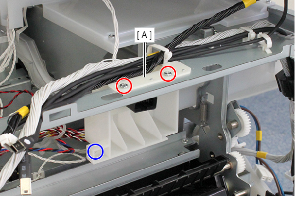
- : C.B.S-TITE-SCREW-3x8-F.ZN-3C
 : C.B.S-TITE-SCREW-3x8-F.ZN-3C
- Remove the screw, and remove the Heat Vent Cover (A).
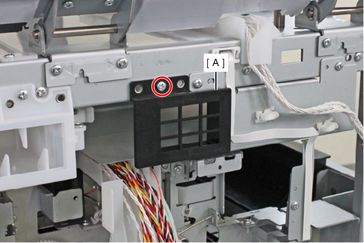
- : C.B.S-TITE-SCREW-3x8-F.ZN-3C
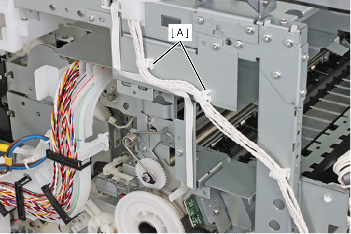
- Release the cable from the two clamps (A).
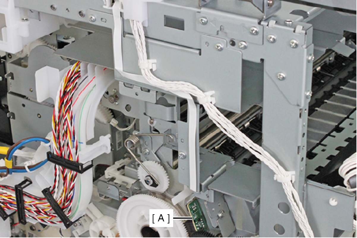
- Remove the FFC from the connector of the PF Encoder Assy (A) and release the FFC by peeling away the double-sided tape.
 Caution / 注意
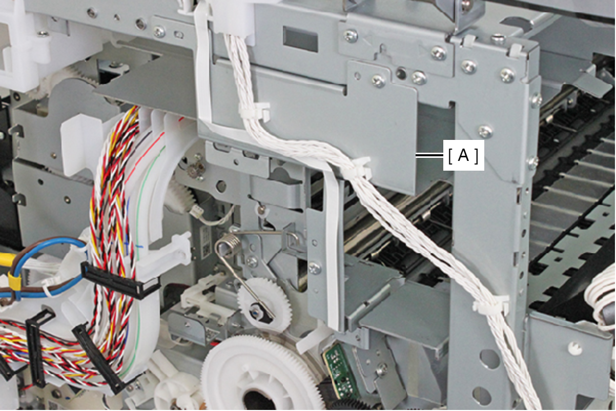
When removing the PS Guide Left (A), be careful not to damage the cable or FFC on the sharp edge of the PS Guide Left(A).
- Remove the three screws and remove the PS Guide Left (A) toward the direction of the arrow.
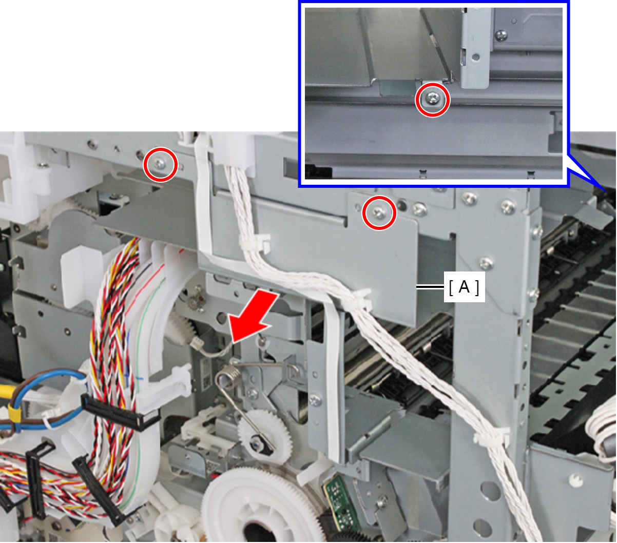
- : C.B.S-TITE-SCREW-3x8-F.ZN-3C
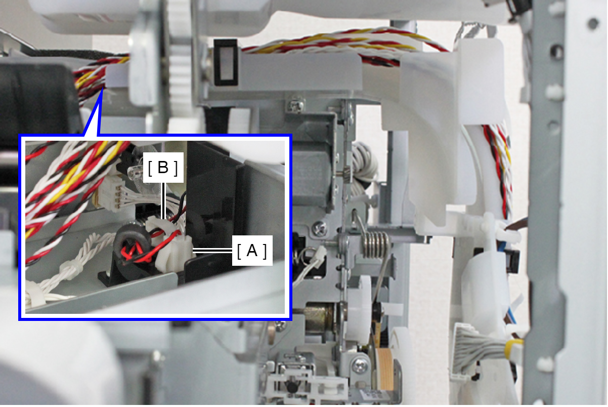
- Remove the APG Motor Cable from the Relay Connector (A) and free it from the clamp (B).
- Remove the two screws fastening the APG Motor Assy (A).
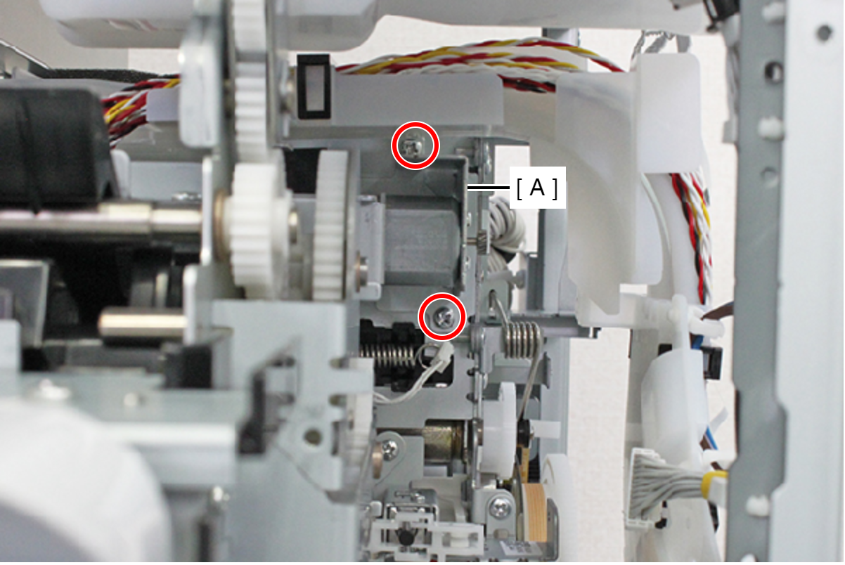
- : C.B.S-TITE-SCREW-3x6-F.ZN-3C
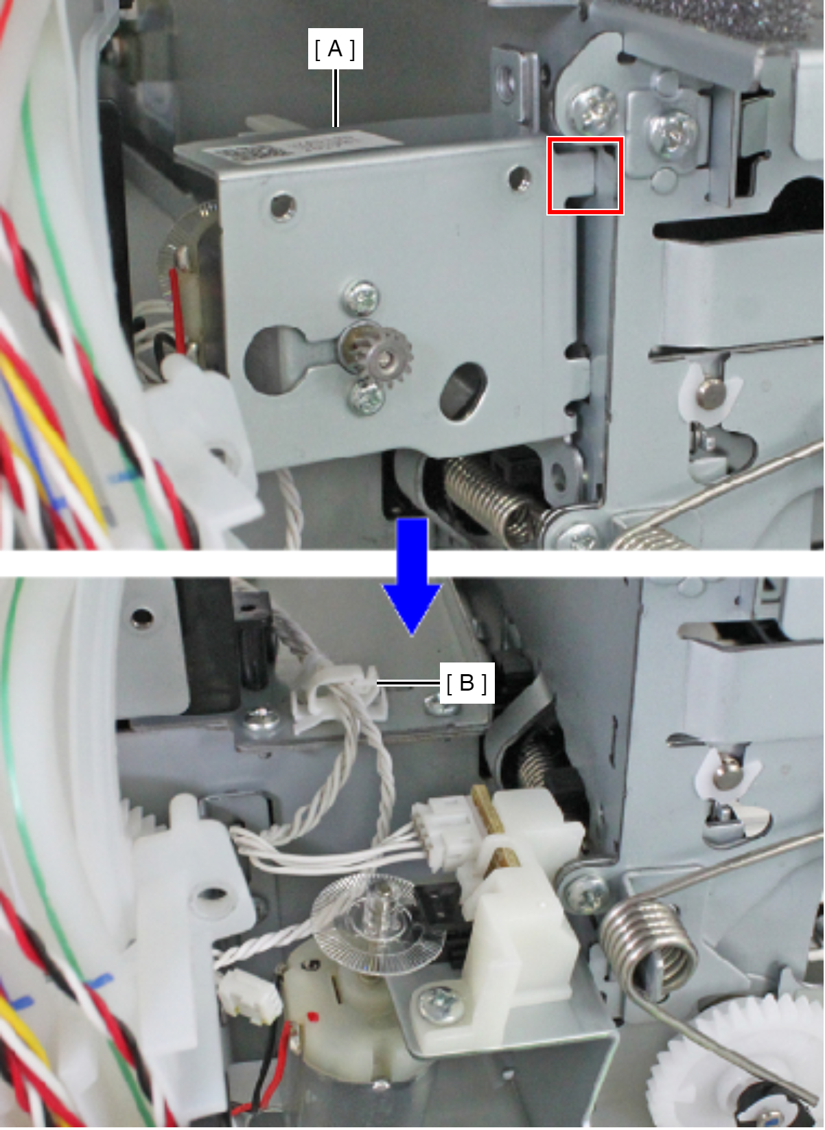
Caution / 注意The APG Encoder Cable is routed to the inside of the printer so when implementing the next step, be careful not to pull strongly on the APG Motor Assy.
- Pull the APG Motor Assy (A) slowly to the front by releasing the hook, and release the APG Encoder Cable from the clamp (C).
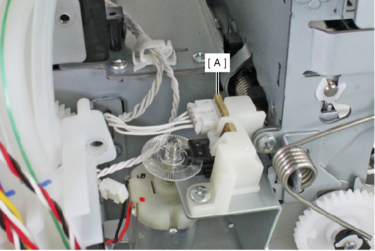
- Remove the cable from the connector of the APG Encoder (A) and remove the APG Motor Assy.
- Remove the five screws, and remove the PS Guide Right (A).
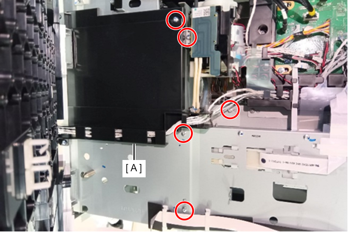
- : C.B.S-TITE-SCREW-3x8-F.ZN-3C
- Remove the two screws fastening the Cable Holder (A).
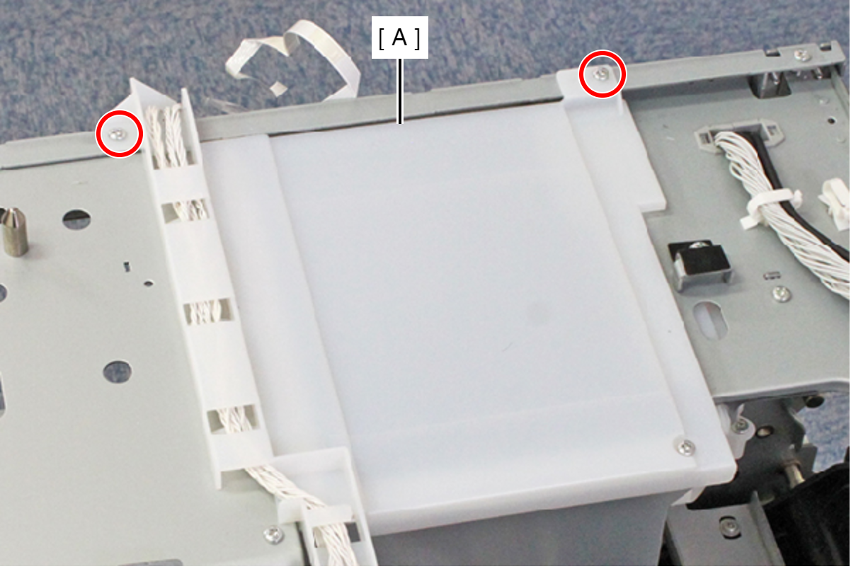
- : C.B.S-TITE-SCREW-3x8-F.ZN-3C
- Release the cable, and remove the Cable Holder (A).
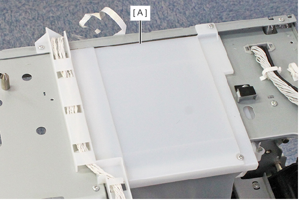
- Remove the screw and remove the Duct.
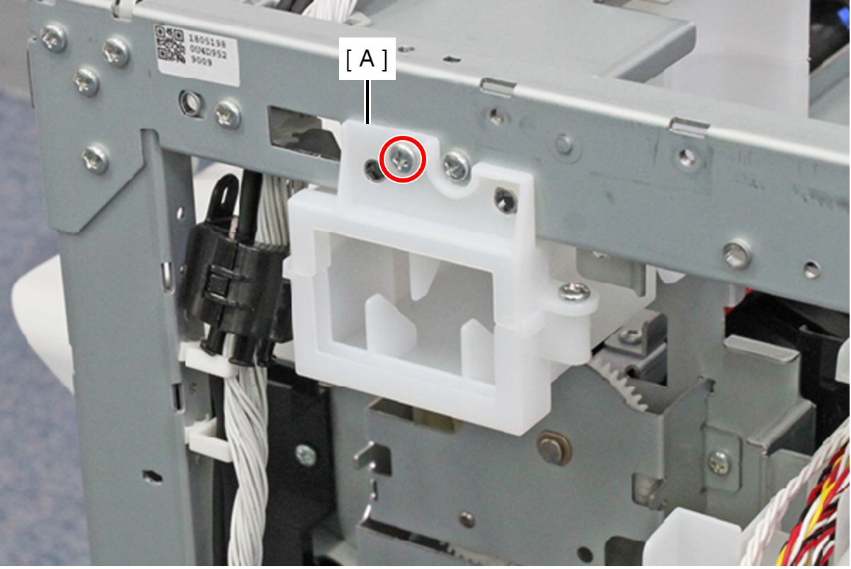
- : C.B.S-TITE-SCREW-3x8-F.ZN-3C
- Release the Intermediate Release Solenoid Cable (B) from the cable clip (A).
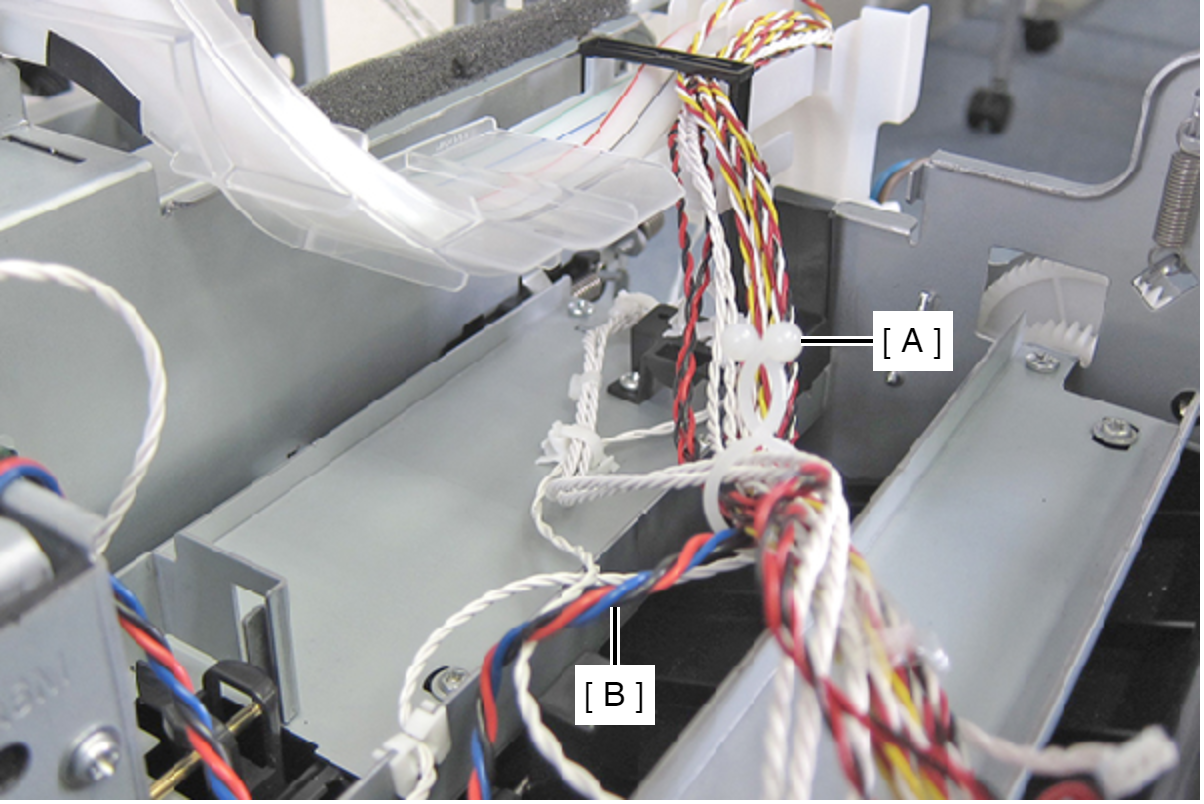
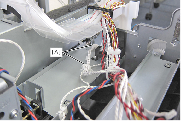
- Release the APG Encoder Cable and the APG Phase Sensor Cable from the two clamps (A).
- Remove the six screws, and remove the Uway Drive Assy (A).
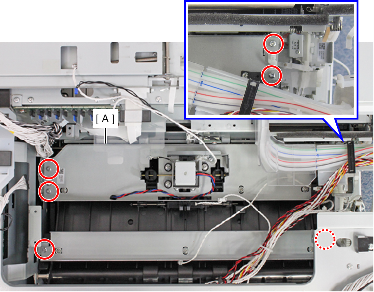
- : C.B.S-TITE-SCREW-3x6-F.ZN-3C
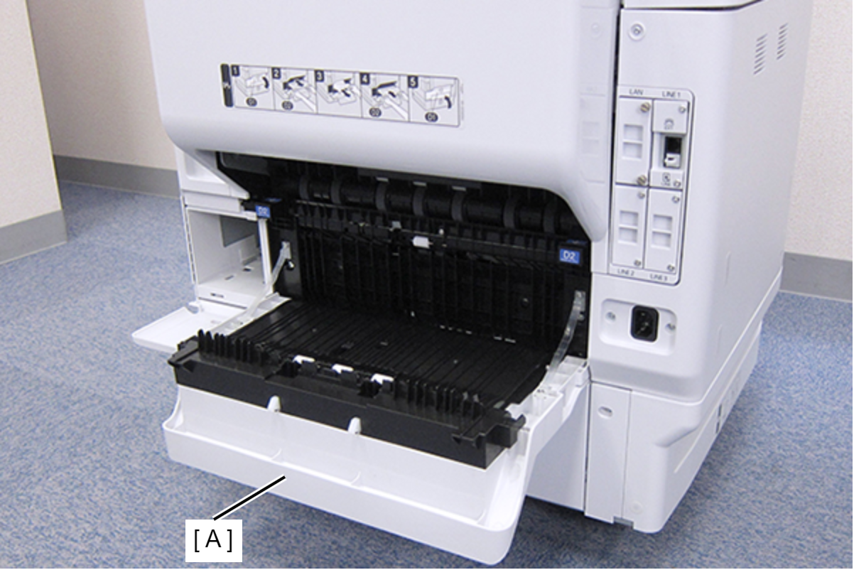
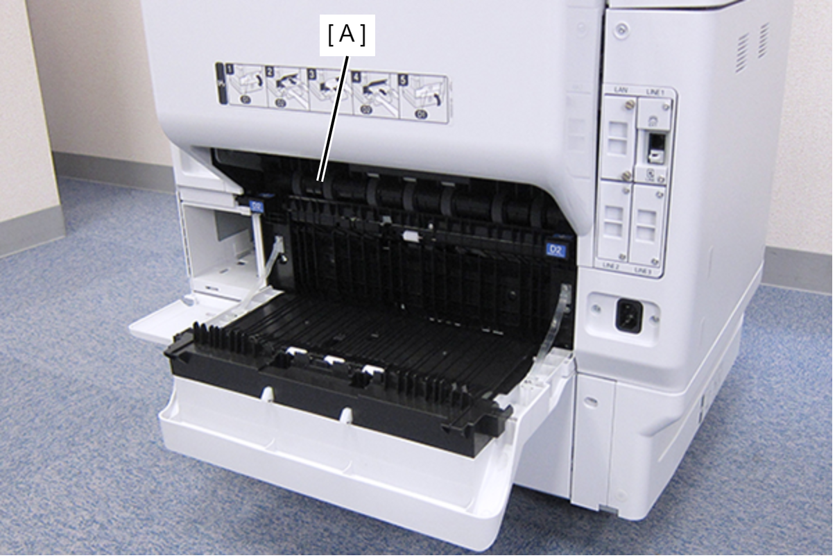
- Open the Duplex Print Cover (A).
- Remove the Duplex Print Assy (A).
- Remove each screw and remove the four Release Shaft Holders.
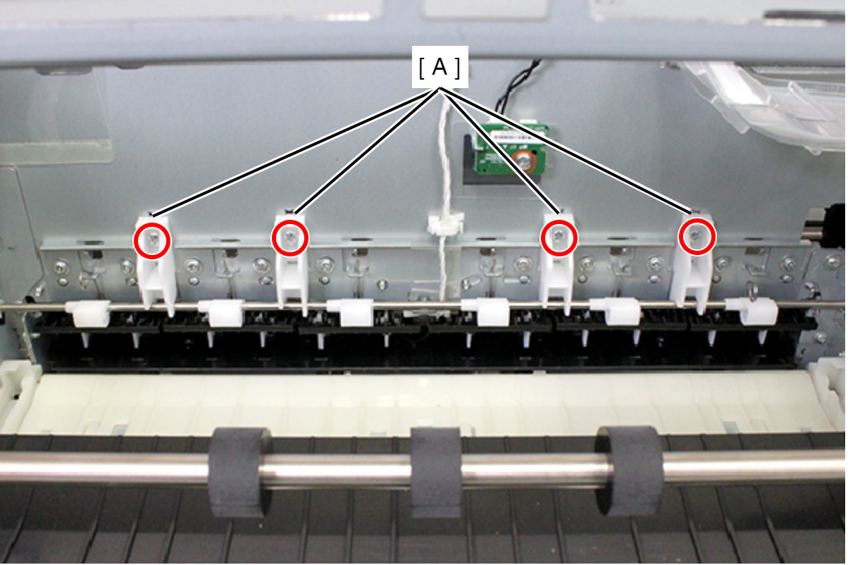
- : C.B.S-TITE-SCREW-3x8-F.ZN-3C
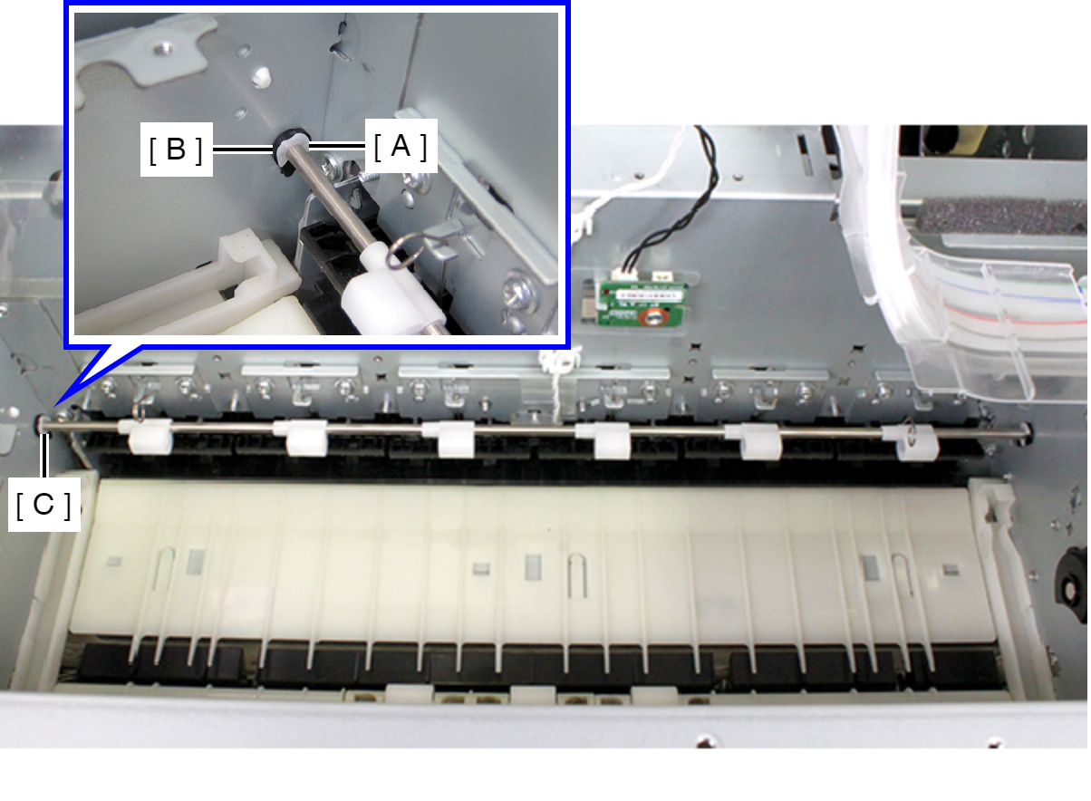
- Remove the E-ring (A) and remove the bushes (B) from the hole in the home-side frame.
- Slide the Release Shaft (A) in the direction of the arrow and remove the Release Shaft (A) from the hole in the full-side frame (B).
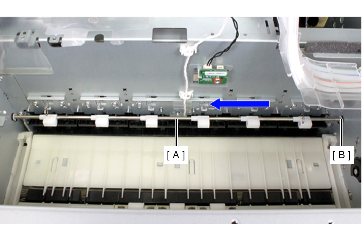
- Remove the Release Shaft while tiling at an angle.(A)
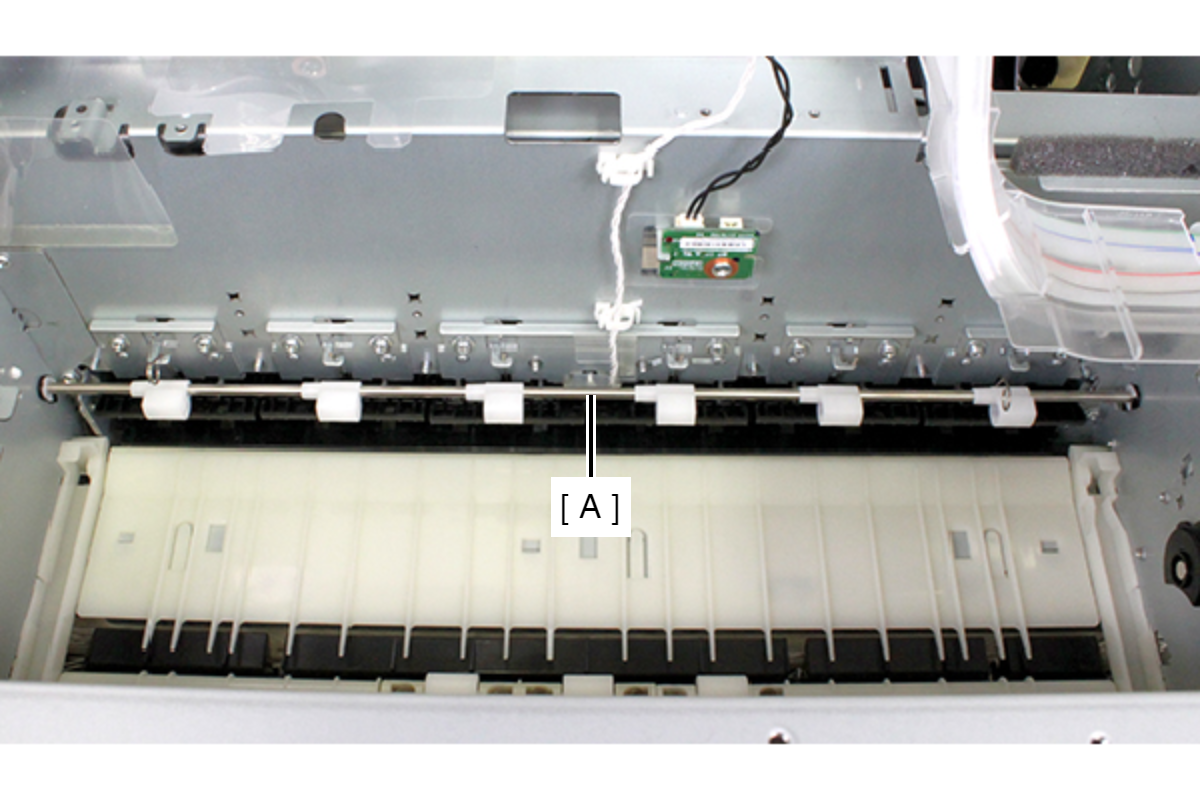
- Remove the torsion spring from the hook.
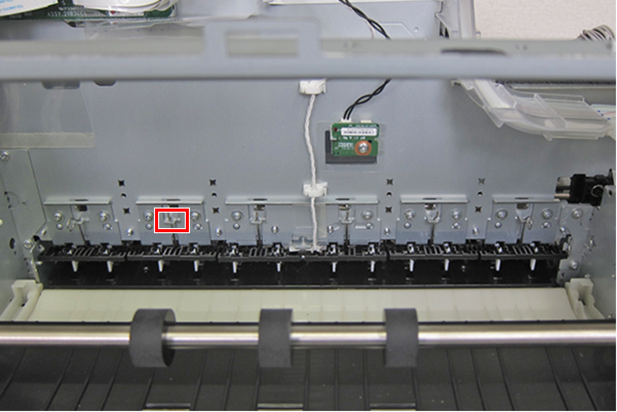
- Remove the two screws, and remove the Paper Guide Upper Center Right (A).
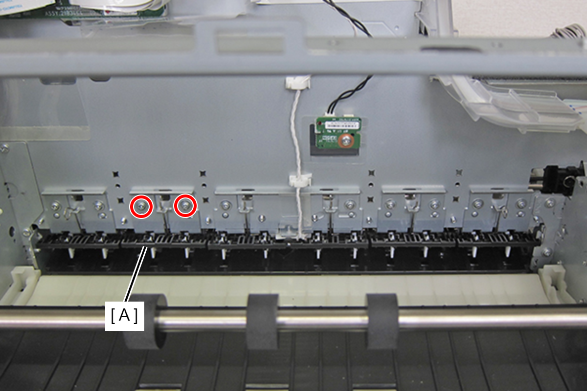
- : C.C-SCREW-3x5-F.ZN3C
| Adjustment / 調整 |
After replacing this part, you need to run the menu from the service support mode. (If you ran the Before-replacement menu before replacing the part, it will start automatically when you turn the power on.) |