Ink Leak Sensor Assy
 Caution / 注意 Caution / 注意 |
|
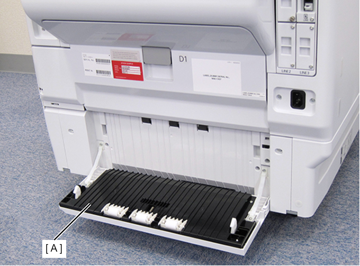
- Open the Paper Jam Clear Cover (A).
- Remove the screw on the rear side of the product, then remove the Paper Jam Clear Cover Holder (A).
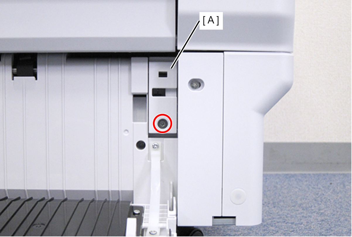
 : C.B.S-TITE-SCREW-3x8-F.ZN-3C
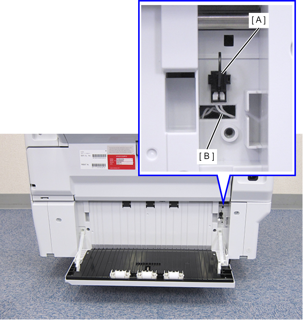
- Disconnect the cable (B) from the connector of the Paper Jam Clear Cover Sensor (A).
- Remove the four screws that secure the Rear RIPS Housing Assy (A).
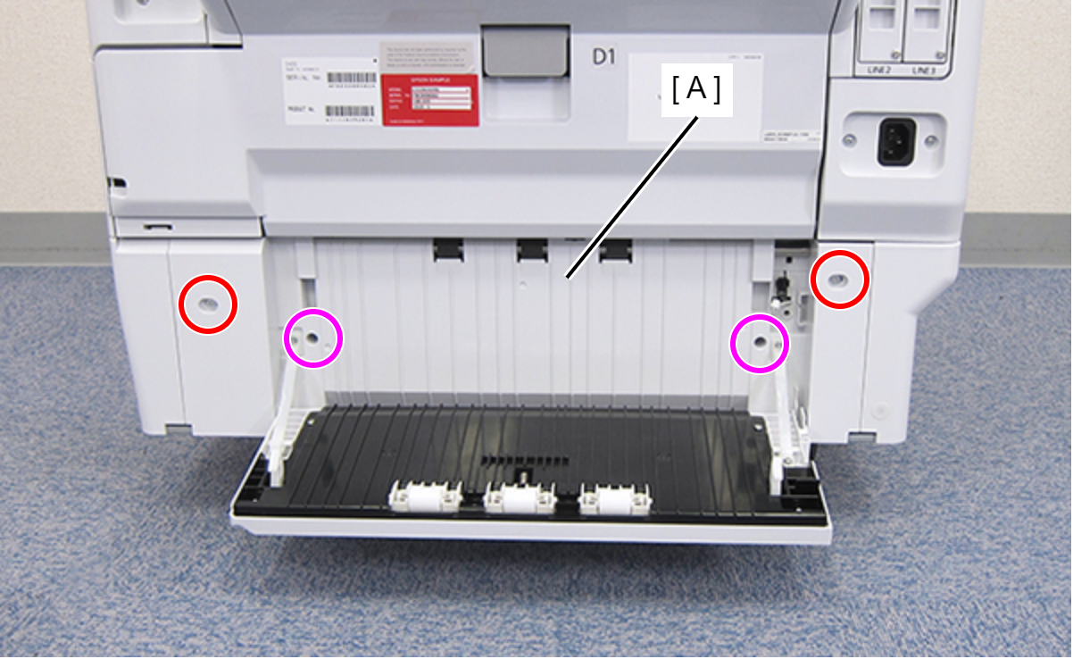
 : C.SHOULDER S-TITE,3X5
 : C.B.P-TITE-SCREW-3x10-F.ZN-3C
- Remove the Rear RIPS Housing Assy (A) pulling out the cable (C) through the hole (B) of the assy.
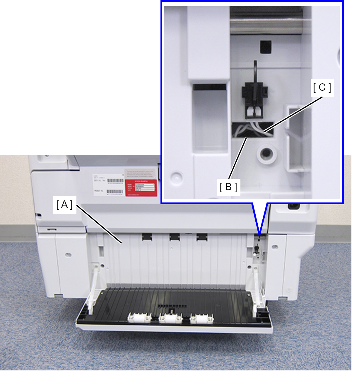
 Assembly / 組み立て
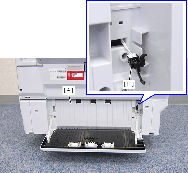
Before reinstalling the Rear RIPS Housing Assy (A), remove the Paper Jam Clear Cover Sensor (B). After connecting the cable, install the sensor to the Rear RIPS Housing Assy.
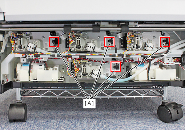
- Pull the Decompression Tube from the four Connecting Ports (A) on the Ink Supply Unit.
- Pull the Decompression Tube in the Decompression Pump Unit (B) from the two Tube Joints (A).
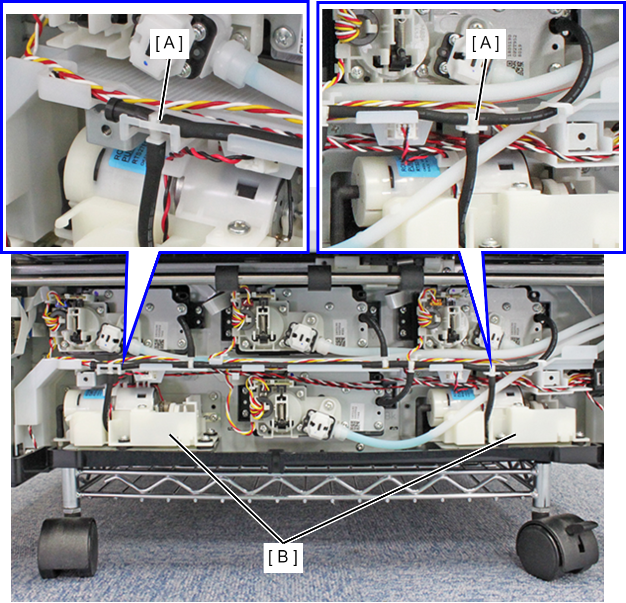
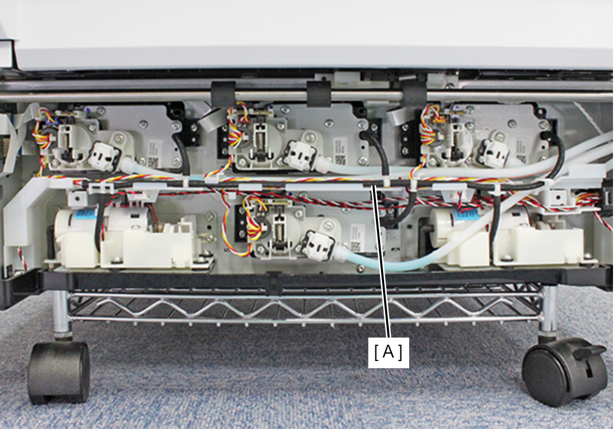
- Release the Decompression Tube from the Tube Guide in the Ink Leak Sensor Assy, and remove the Decompression Tube Assy (A).
- Remove the screw that secures the Ink Tube Holder (A).
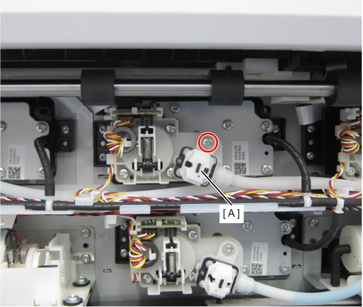
- : C.B.P-TITE-SCREW-3x10-F.ZN-3C
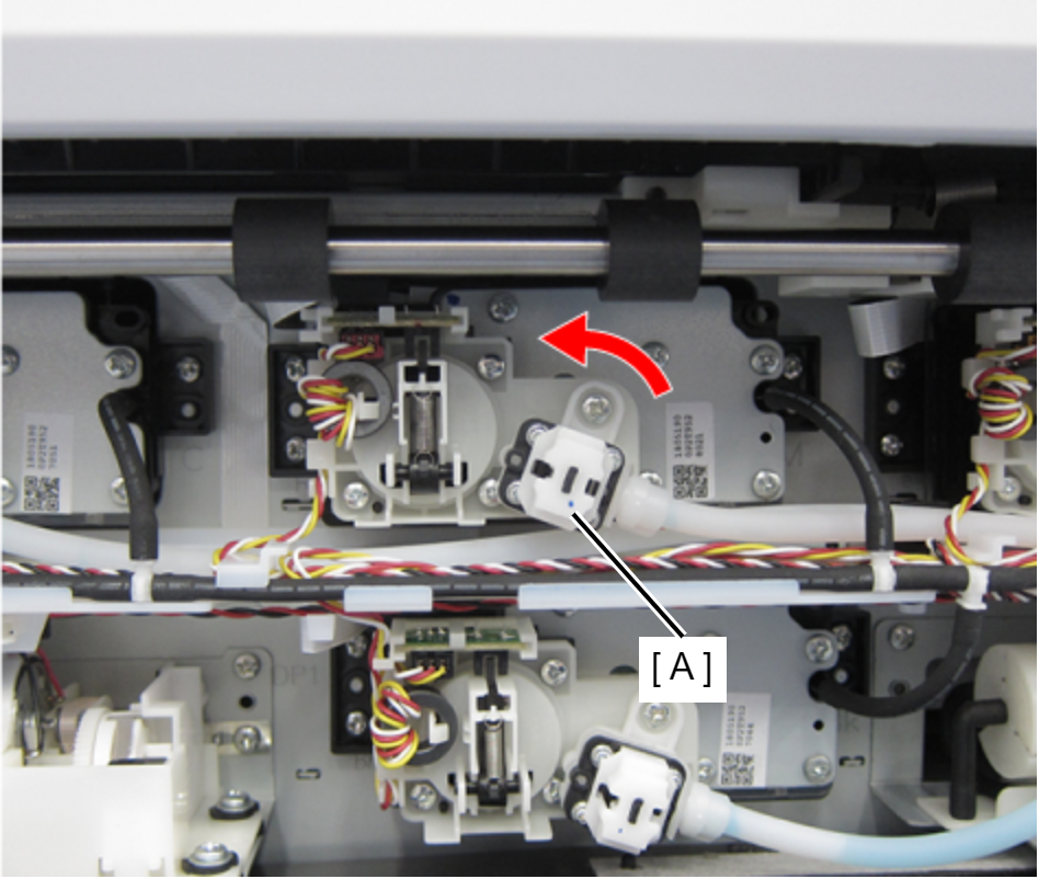
Rotate the Ink Tube Holder (A) counterclockwise, and then remove the Ink Tube Holder.
 Caution / 注意
When removing or attaching the Ink Tube Holder (A), move it straight up or down to prevent its inlet from being tilted.
Pull out the Decompression Tube (A).
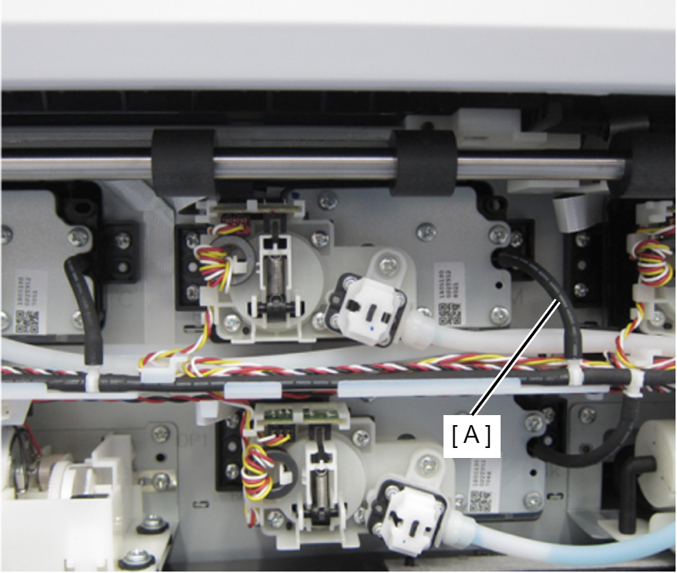
- Remove the three screws, then remove the Ink Supply Unit (A).
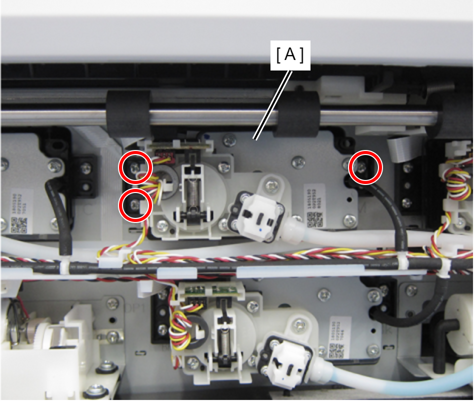
- : C.B.S-TITE-SCREW-3x8-F.ZN-3C
- Disconnect the CSIC FFC (B) from the connector (A).
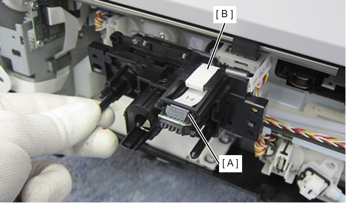
- Disconnect the CRCM FFC (B) from the CRCM board (A).
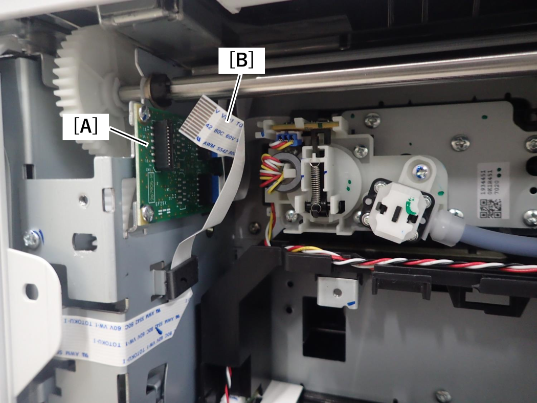 Assembly / 組み立て
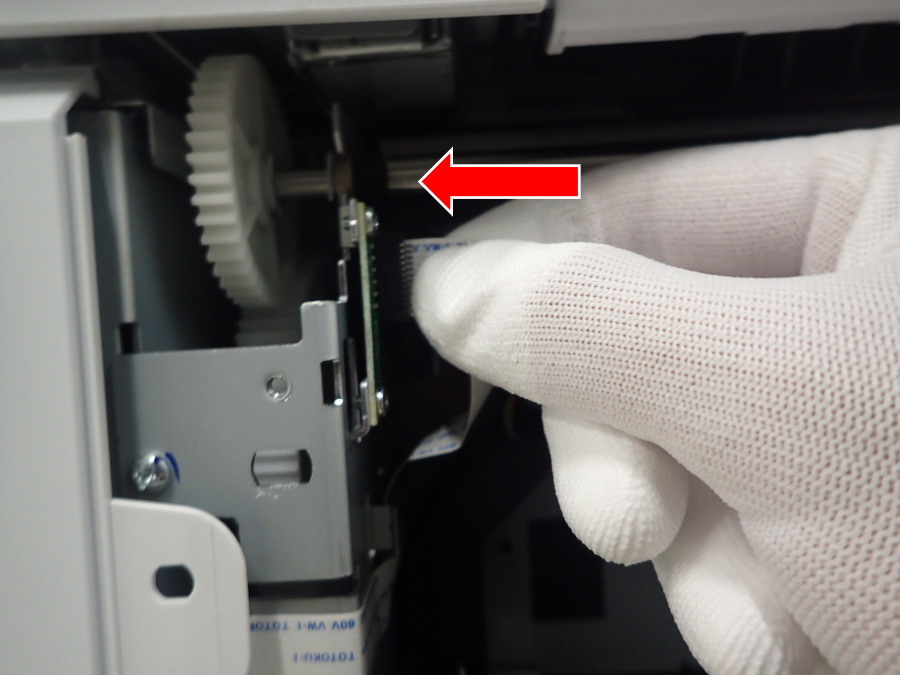
Insert the FFC while holding it.
Do not press the folded part of the FFC (to prevent it from breaking at the end of the reinforcing plate).
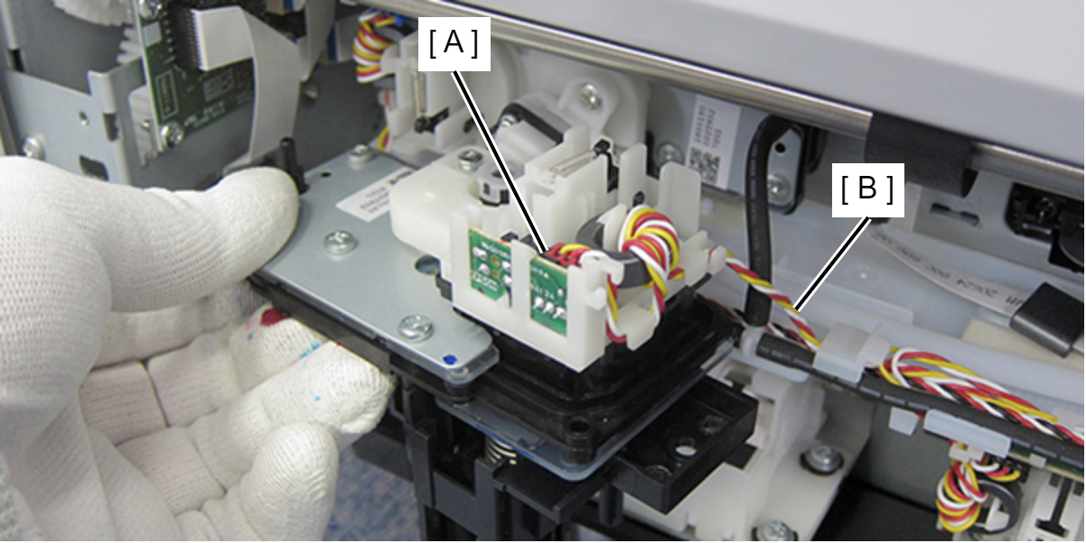
- Disconnect the Ink End Sensor Cable (B) from the connector (A).
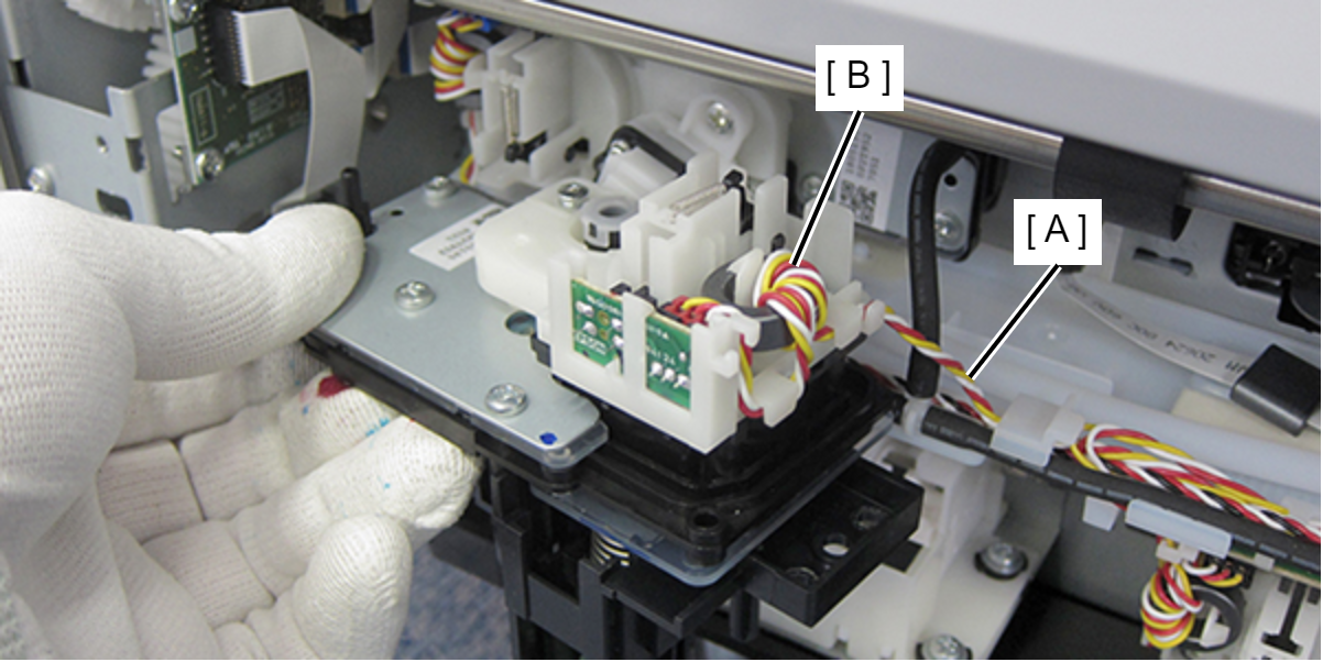
- Remove the ferrite core (B) from the Ink End Sensor Cable (A).
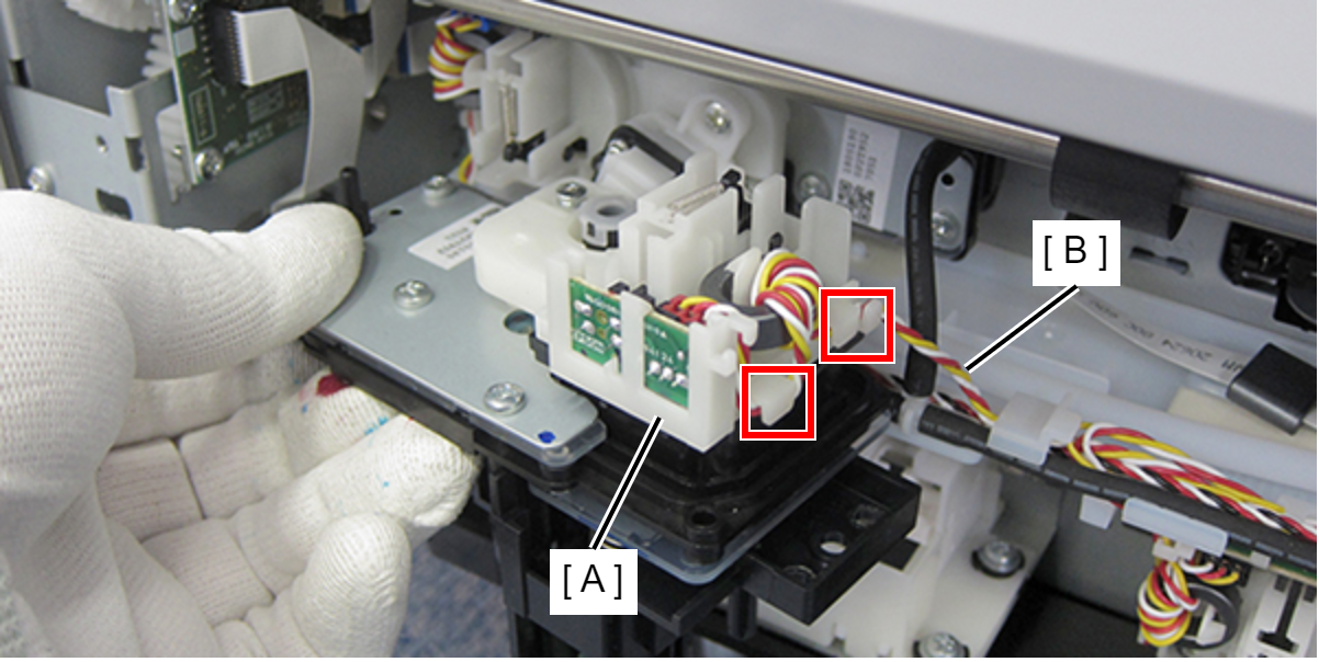
- Release the Ink End Sensor Cable (B) from the hook of the holder (A).
 Assembly / 組み立て
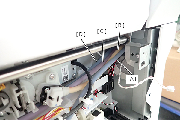
As shown below, arrange the Ink Tubes in the order of Black (A), Yellow (B), Magenta (C), and Cyan (D), from the back face side.
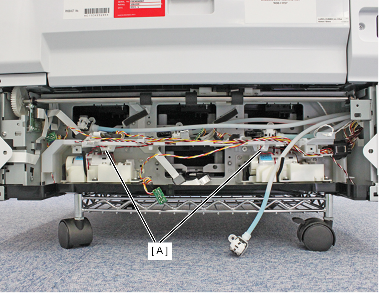
- Remove the two cables on the Decompression Pump Unit from the two Relay Connectors (A).
- Remove the two screws and pull the Ink Leak Sensor Assy (A) out.
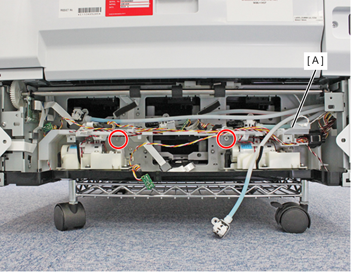
- : C.SHOULDER S-TITE,3X5
- Remove the two Relay Cables (B) from the two Relay Connectors (A).
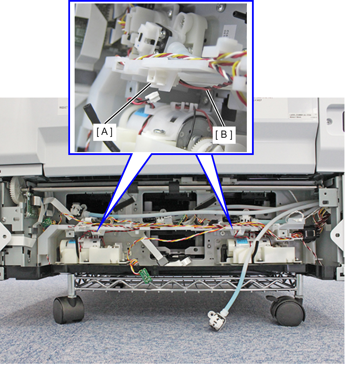
- Release the Ink End Sensor Cable from each hook and remove it from the Ink Leak Sensor (A).
Release all cables from the Ink Leak Sensor Assy (B).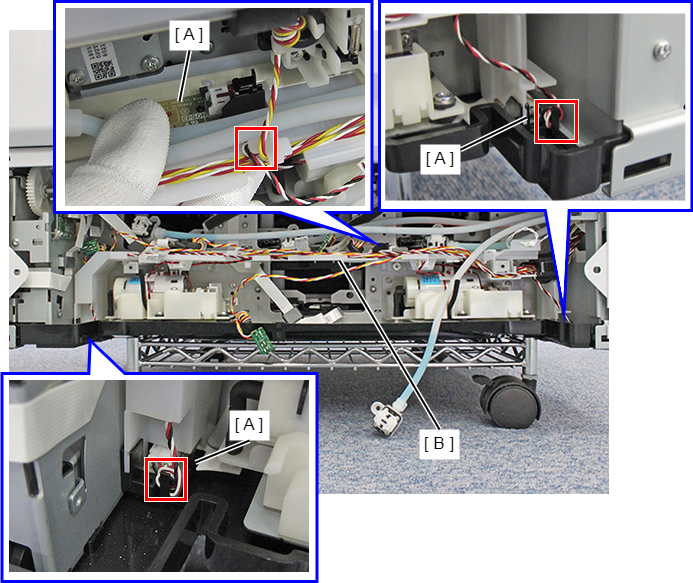
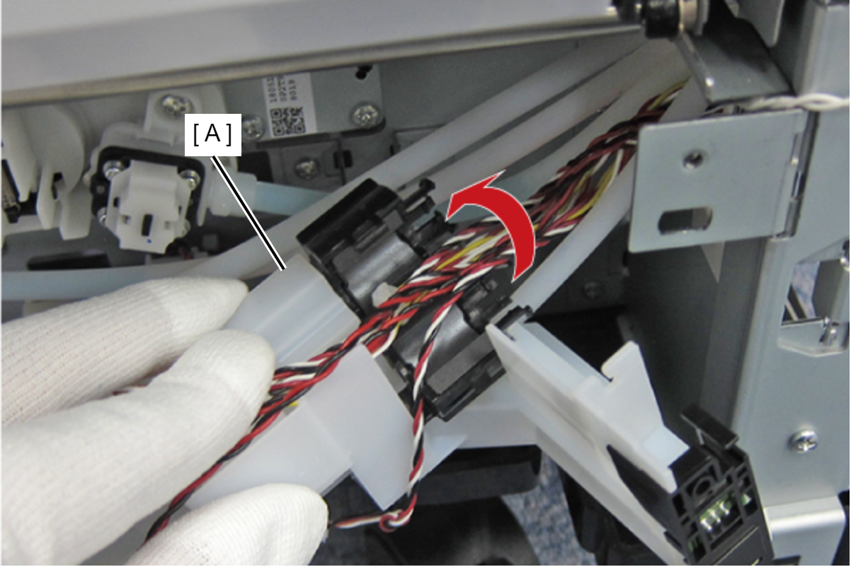
- Release the cable by releasing the hook on the Ferrite Core Holder (A) on the right side.
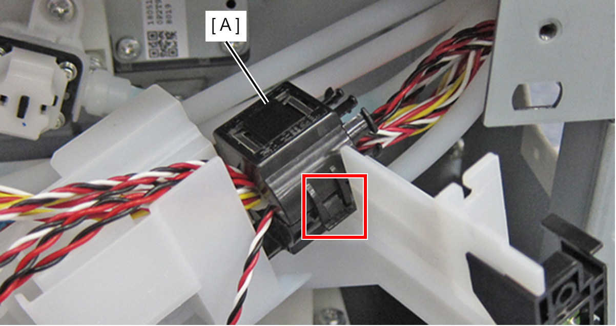
- Remove the Ink Leak Sensor Assy (A).