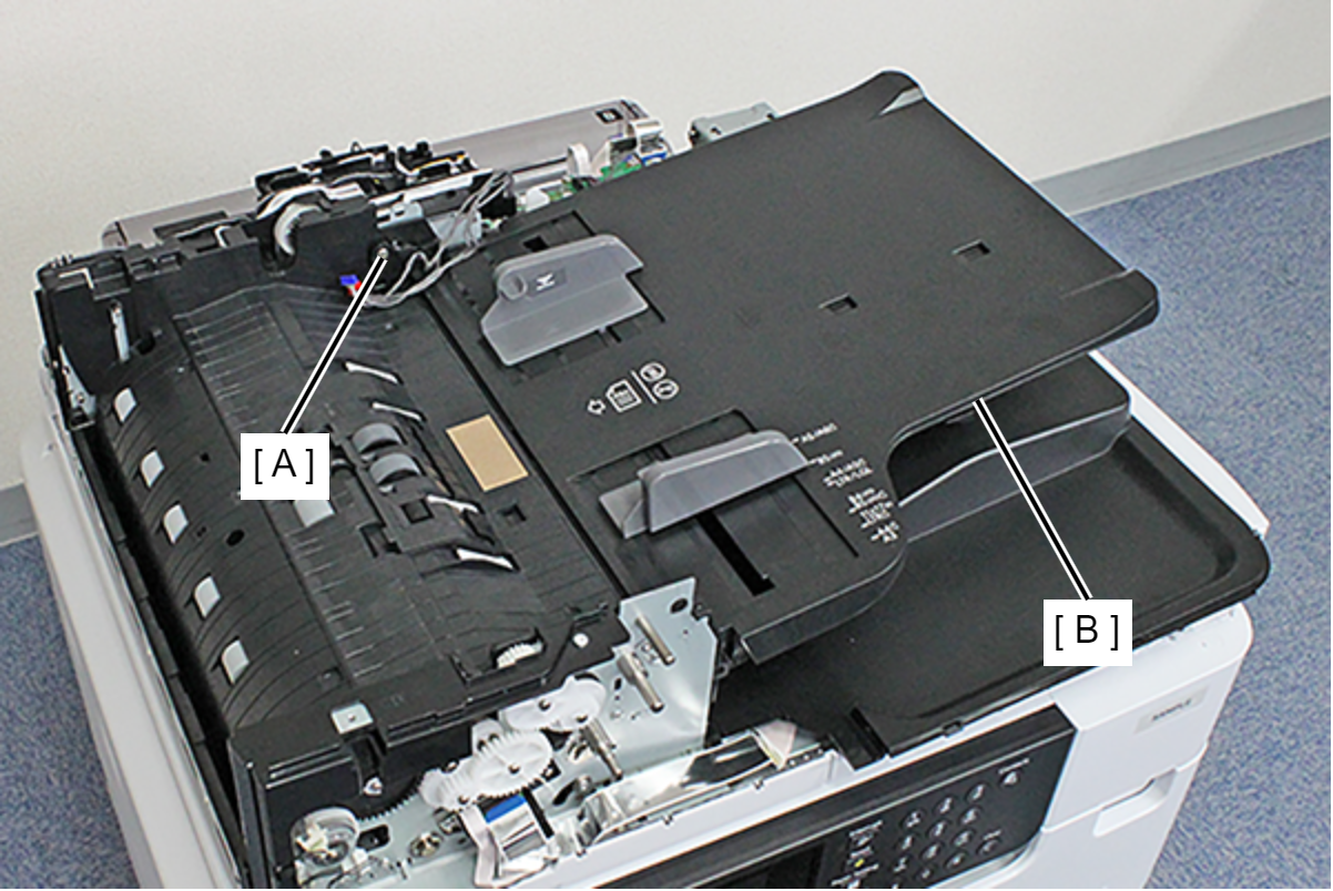
Top ADF Document Support Assy
- Remove the 5 screws, then remove the Rear ADF Cover Assy (A).
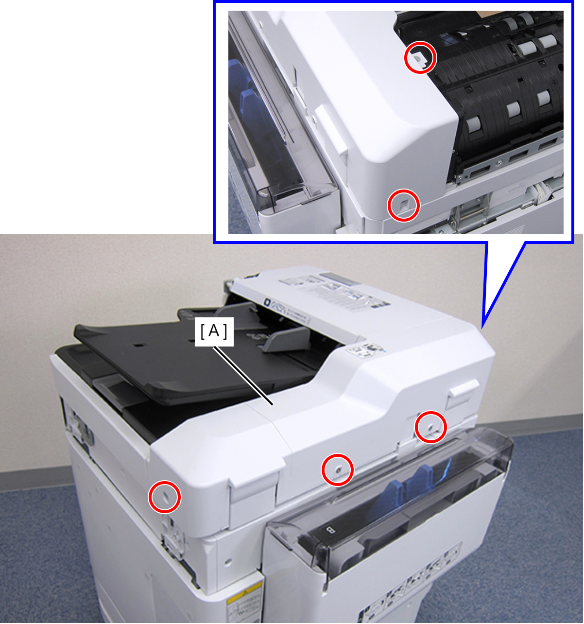
 : C.SHOULDER S-TITE,3X5
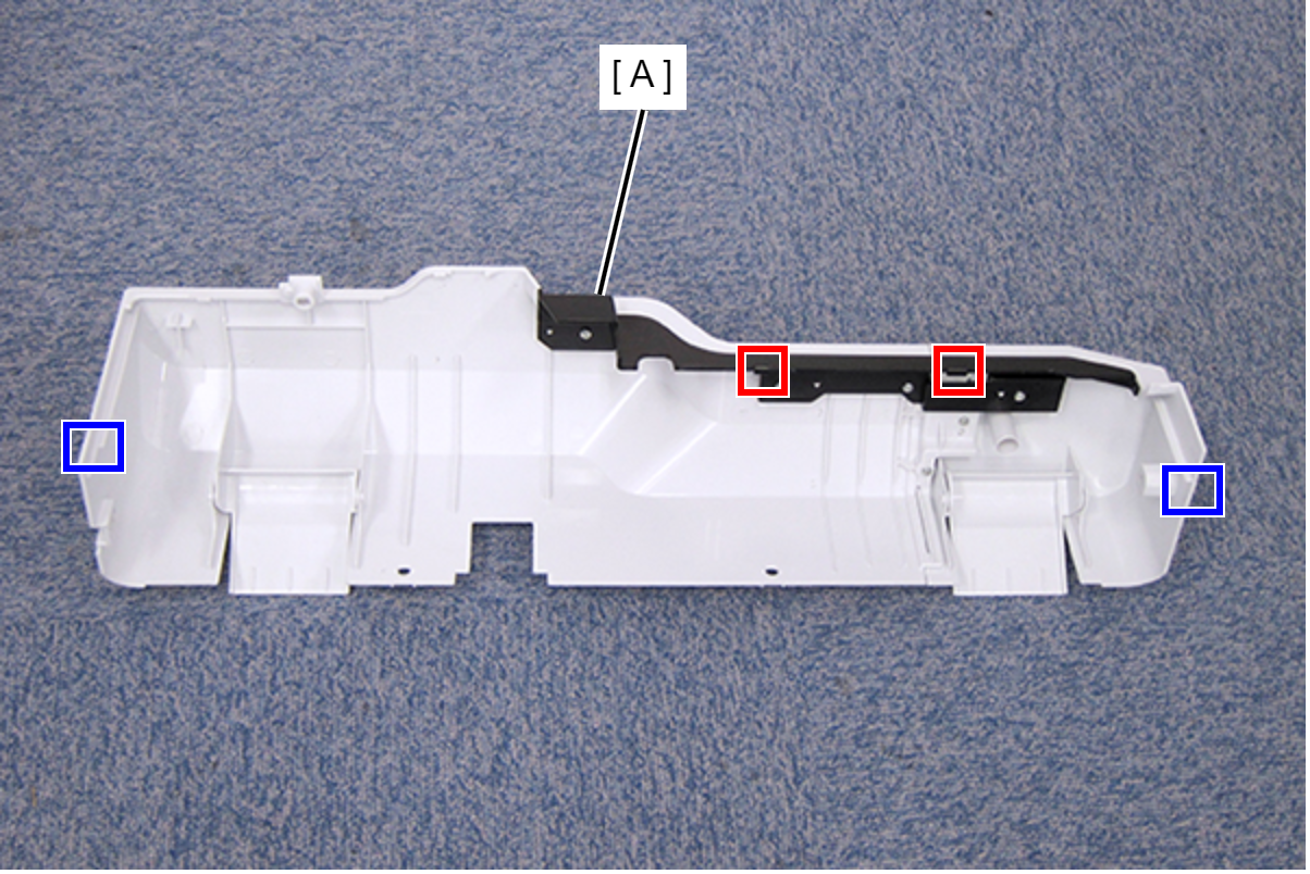
- Disengage the two hooks and the two tabs, then remove the Rear ADF Cover Assy (A).
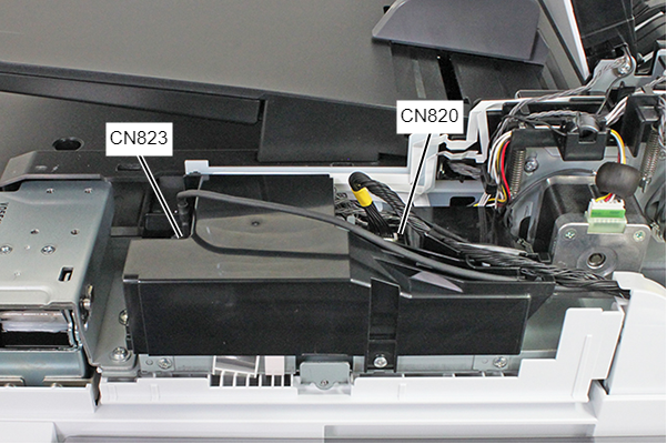
- Remove the cables listed below from the connectors of the ADF Board.
- Cable (USB) (CN823) (With hook)
- Cable (CN820)
- Remove the screw.
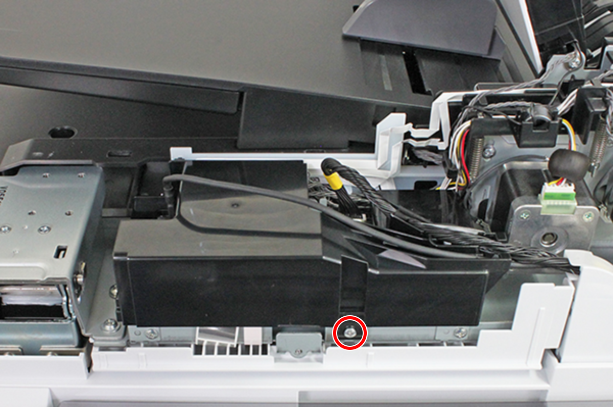
- : C.B.S-TITE-SCREW-3x8-F.ZN-3C
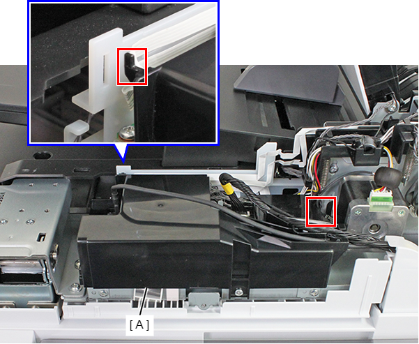
- Remove the ADF Board Cover (A) while releasing the hook.
- Remove the five screws.
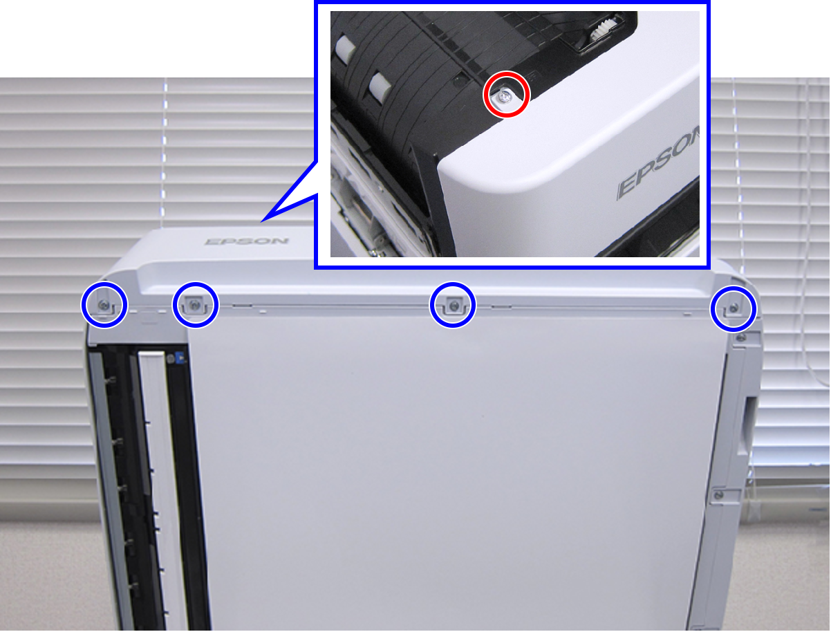
- : C.B.S-TITE.P4.SCREW-3x6-F.ZN-3C
 : C.B.P-TITE.P4.SCREW-3x10-F.ZN-3C
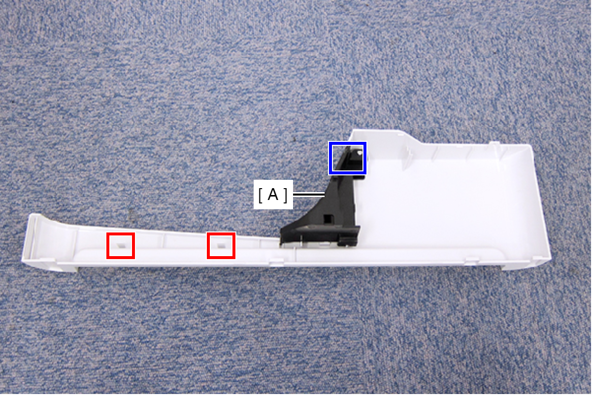
- Disengage the two hooks, and remove the Front ADF Cover Assy (A).
- Remove the C-ring (A).
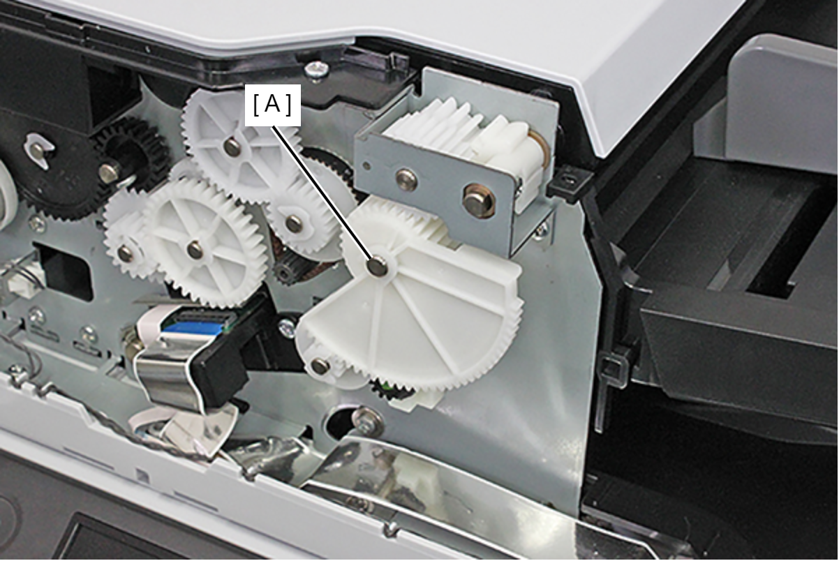
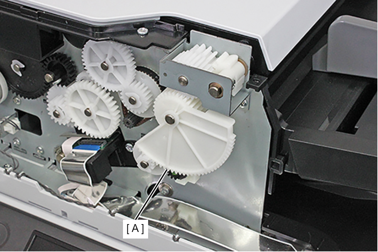
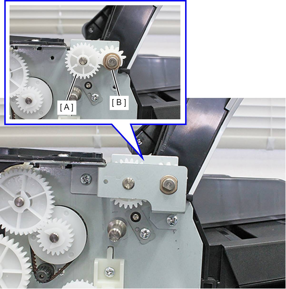
- Remove the combination gear (A).
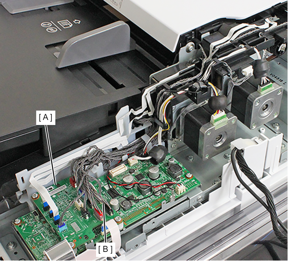
- Remove the cable from the connector (CN6) (B) of the ADF Board (A).
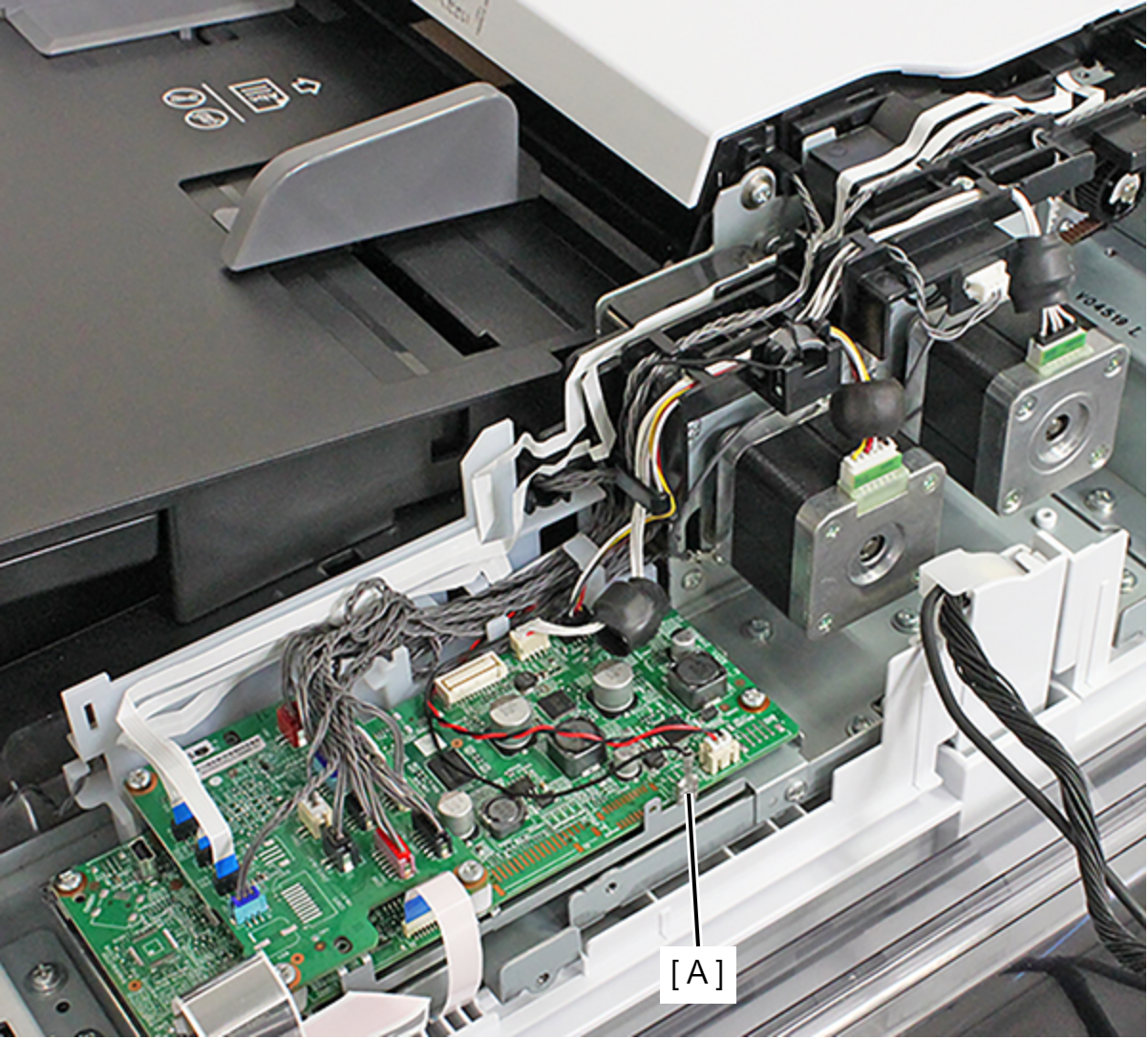
- Remove the Ground Terminal (A).
- Release the cable and the grounding wire from the two hooks.
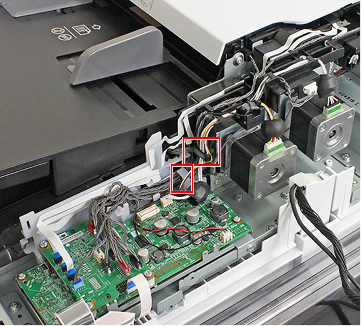
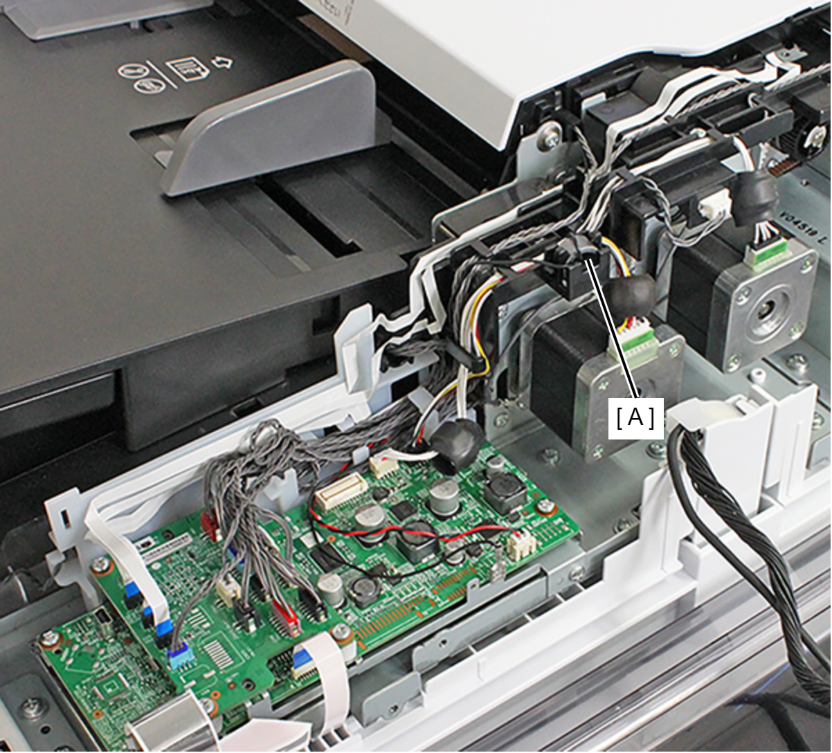
- Remove the ferrite core (A) of the grounding wire.
- Remove the screw, and remove the bearing (A).
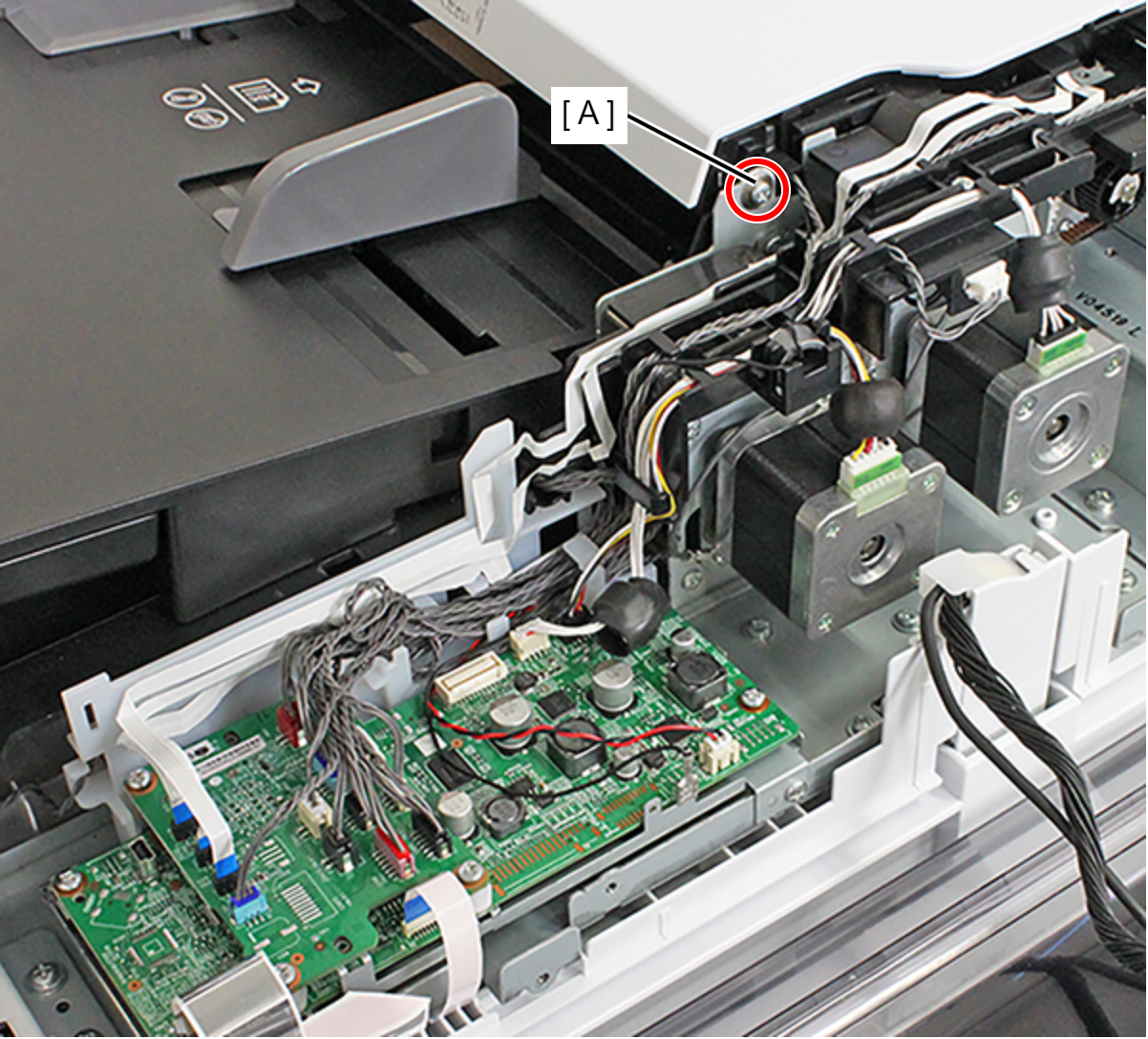
- : C.B.P-TITE-SCREW-3x12-F.ZN-3C
- Remove the two screws, and remove the Damper Frame (A).
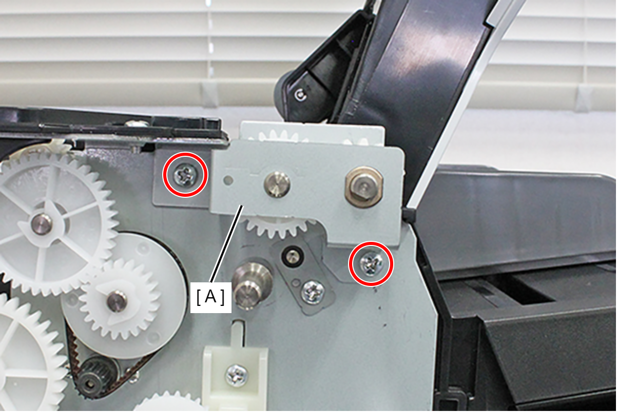
- : C.B.S-TITE-SCREW-3x6-F.ZN-3C
- Remove the combination gear (A) and the bearing (B).
- Remove the screw, and remove the ADF LD Gear (A).
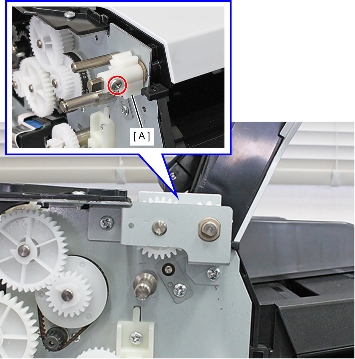
 : C.B-SCREW-3x6-F.ZN-3C
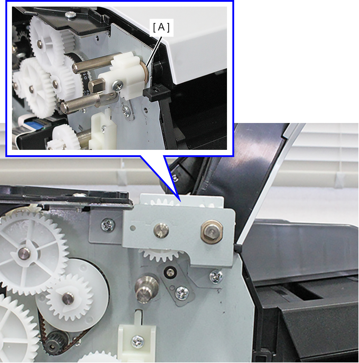
- Remove the bearing (A).
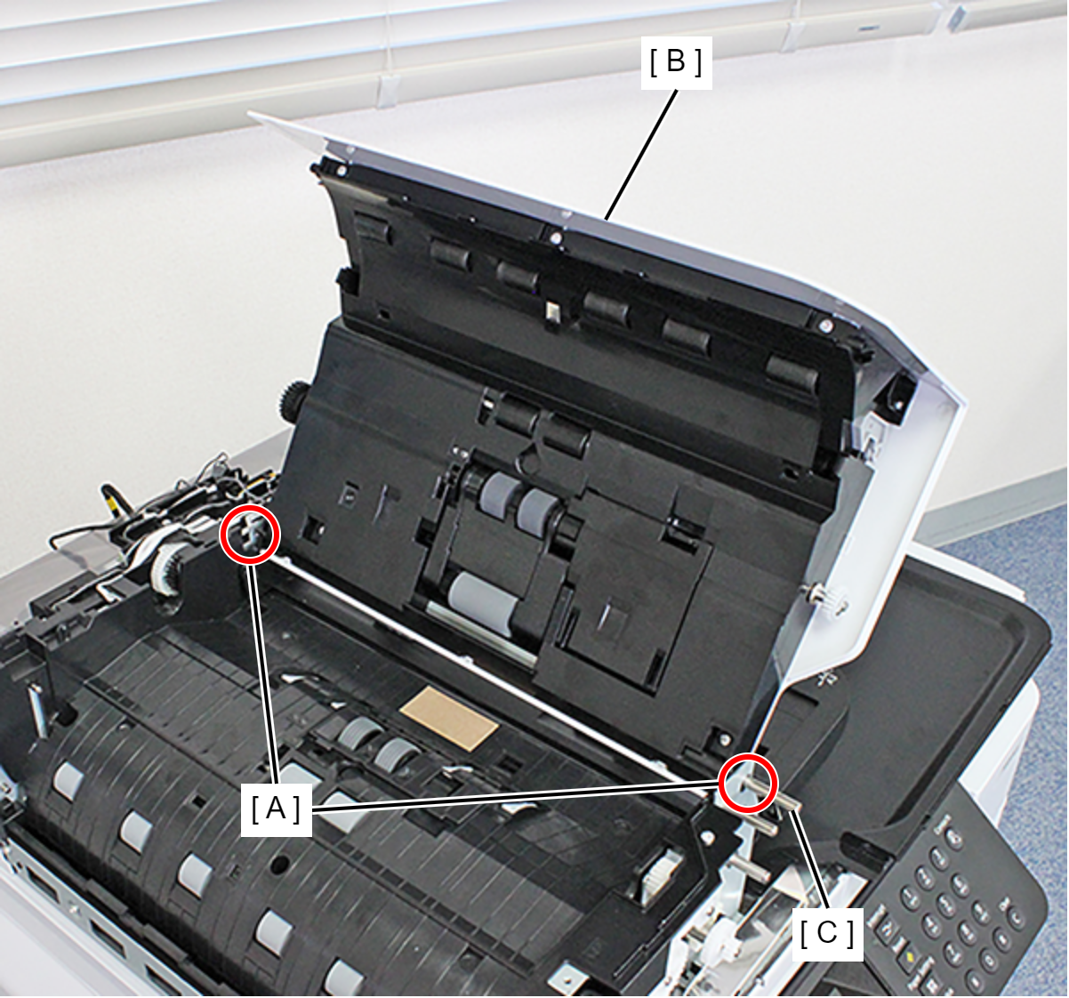
- Pull the ADF Cover Assy (B) shaft (C) from the hole (A) in the frame and remove the ADF Cover Assy (B).
- Remove the cable from the connectors (CN8 (B), CN9 (C)) of the ADF Board (A).
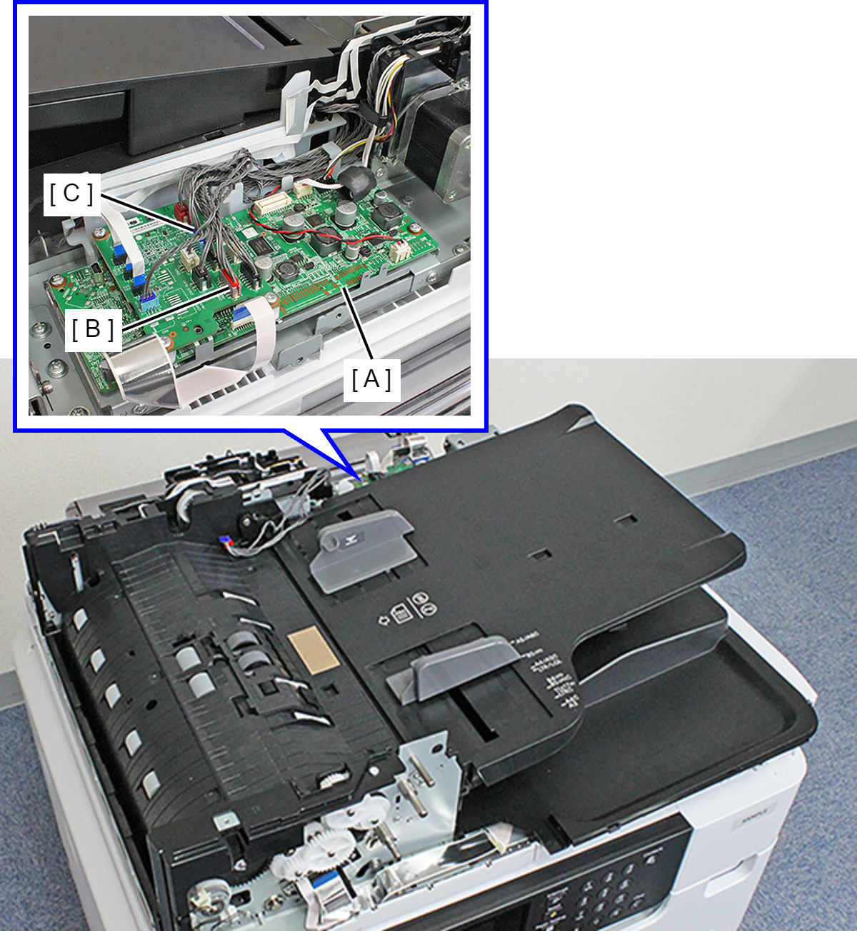
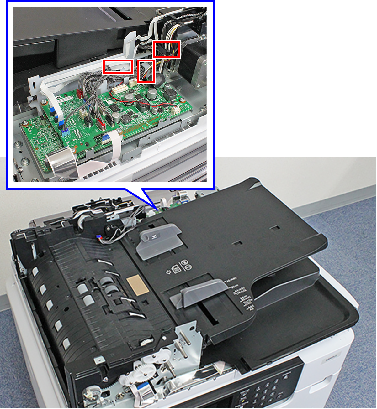
- Release the cables from the three hooks.
- Remove each screw and remove the two Shaft Plates (A) on the front face and the back face.
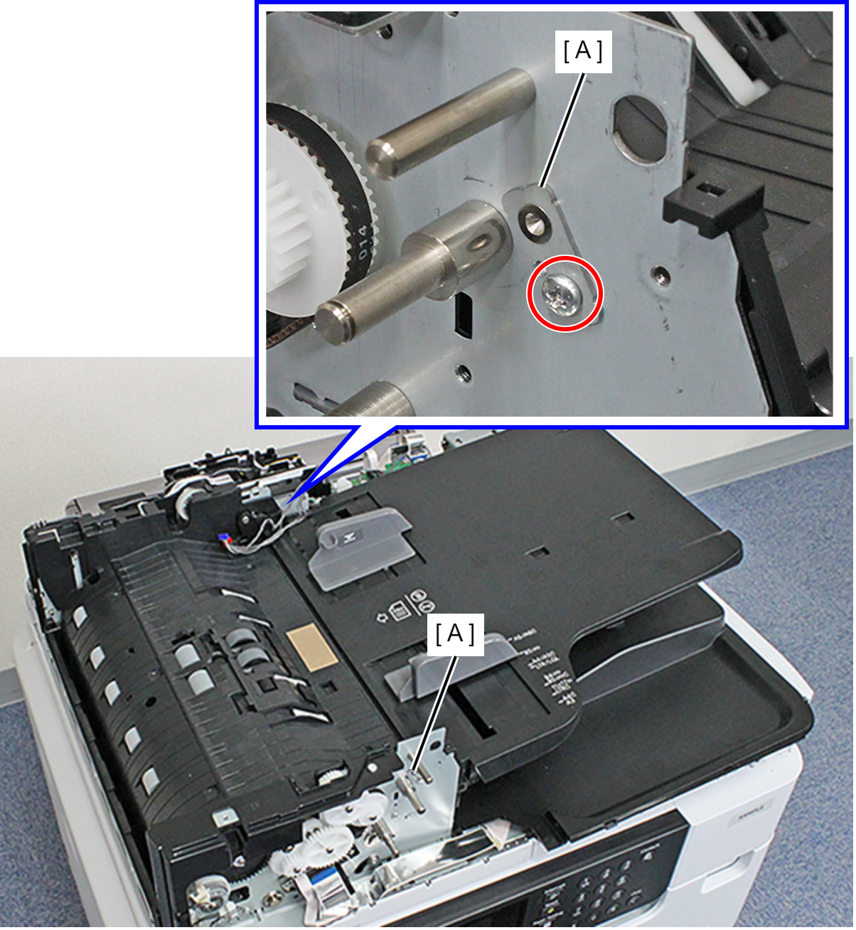
- : C.B.S-TITE-SCREW-3x6-F.ZN-3C
- Pull out and remove the Top ADF Document Support Assy (B) from the shaft (A).