Operation of Each Mechanism
Cap mechanism
When the CR Unit moves to the home position, the Cap Slider is pushed up by the CR Unit and caps the Print Head. When the CR Unit moves away from the home position, the Cap Slider falls and the capping is released (vented to atmosphere).
The ink system mechanism of EM-C8101 Series does not have any venting valves, but this Cap Slider's operation in conjunction with the CR Unit's movement realizes the performance of the traditional venting valves.
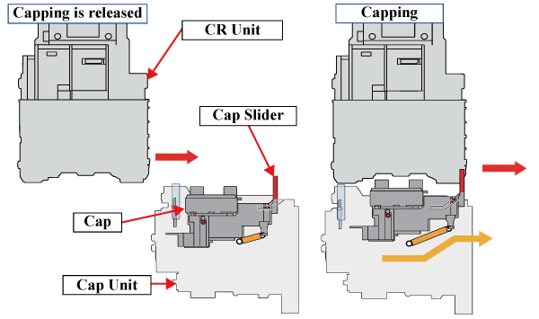
The Cap of EM-C8101 Series has a structure which can move up and down and to the right and to the left following the inclination of the Print Head. Because of this structure, accurate capping can be done even the alignment of the Print Head is changed after the head angular mecha adjustment*1 is done.
In addition, the operation of the cap mechanism controls the drive force to the wiper mechanism and carriage lock mechanism.*1
*1: For the details, see Wiper Mechanism/Carriage Lock Mechanism.
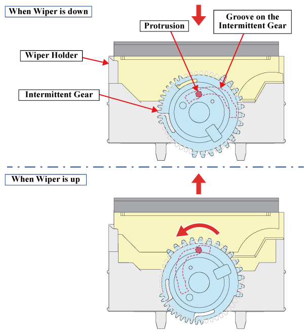
Wiper Mechanism
The wiper mechanism is operated by the rotation of the Intermittent Gear of the IS Clutch Gear. When the Intermittent Gear rotates, the protrusion of the Wiper Holder moves along the groove on the Intermittent Gear to move the Wiper Holder up and down.
Carriage Lock Mechanism
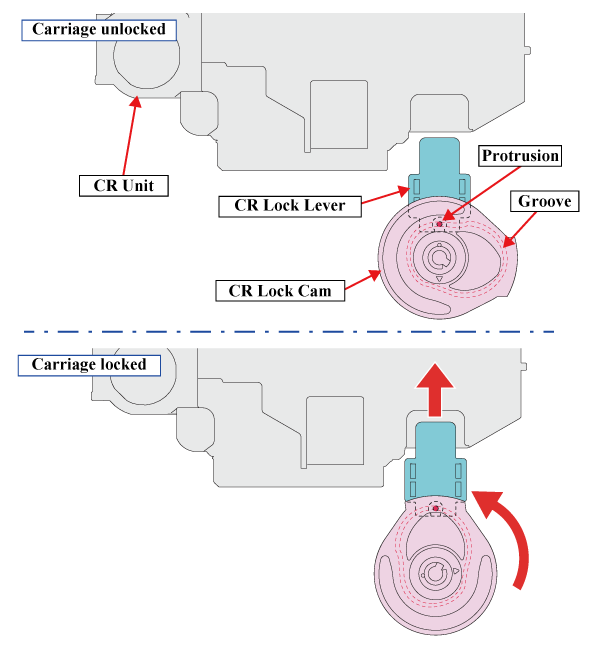
Carriage lock drive mechanism
The carriage lock mechanism is operated by the rotation of the CR Lock Cam. When the CR Lock Cam rotates, the protrusion of the CR Lock Lever moves along the groove on the CR Lock Cam to move the CR Lock Lever up and down.
CR lock lever mechanism
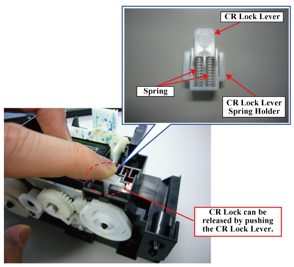
The CR lock lever is composed of the CR lock lever holder, CR lock lever and spring, and it is a structure that the CR locking lever can be released by pushing the CR locking lever even in the state of the carriage lock.
Therefore, CR lock can be released by pushing the CR lock lever when the CR lock drive part is damaged and CR lock can not move condition.
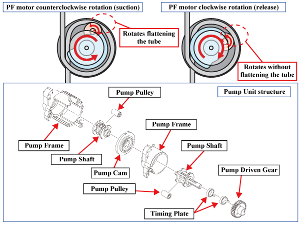
Pump Mechanism
The pump mechanism sucks ink from the Print Head during cleaning.
The drive force from the Pump Driven Gear is transmitted to the Pump Shaft because the two hooks on the Timing Plate are engaged in turn by the rotation of the Pump Driven Gear. Because of the Timing Plate, the starting point of Pump Driven Gear's rotation and that of the Pump Shaft differ so that the pump operation starts after the PF Motor's rotation reaches the predetermined degree.
When the PF Motor rotates counterclockwise, the drive force transmitted via the Pump Driven Gear rotates the Pump Pulley while the pulley presses the tube flat, sucking is made (negative pressure is generated). When the PF Motor rotates clockwise, the Pump Pulley rotates without pressing the tube flat, the negative pressure is not generated (released).