
Head Angular Adj. Mech [B43]
Paper and Feed Tray
- Paper Size: A4
- Paper Type: Matte Paper-Heavy weight/Premium Presentation Paper Matte
- Feed Tray: Rear tray
Adjustment pattern
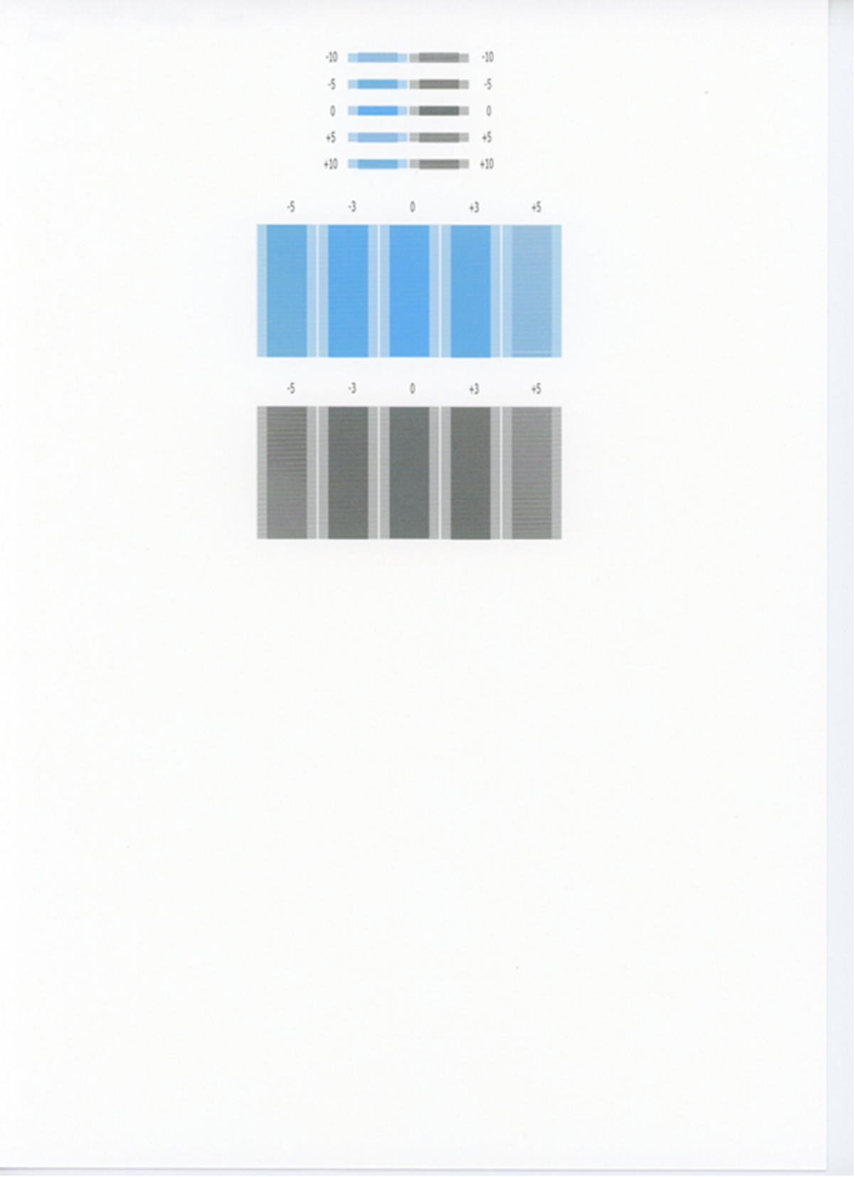
Judgment
Make adjustments so that the spacing between the pattern lines when the adjustment value is “0” becomes equal.
Adjustment procedure
- Start the service support mode. (Service mode startup and operating procedures)
- Select “Adjustment Main Unit: MENU” from the service support mode top menu.
Select “Head Angular Adj. Mech”.
 Check Point / チェックポイント
Select and execute the corresponding adjustment item using either procedure A or B below.
Selecting by entering the program number
- Select “Input B No.-Main Unit Adjust” from the Adjustment menu.
- Press the [#] button and software number key is displayed on LCD. Enter programnumber “43”.
- Press the [#] button.
Selecting from menu
- Select “Individual Adjustment: MENU” from the Adjustment menu.
- Select “Printing Adjust:MENU” from the Individual Adjustment menu.
- Select “Head Angular Adj. Mech” from the Printing Adjust menu.
- The following screen will be displayed.
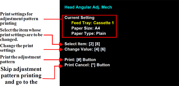
- Load paper into the paper feed tray.
- Press the [#] button to print the adjustment pattern.
Check the adjustment pattern. Check the adjustment pattern and check the adjustment value for which the line spacing is the most equal.
Check Point / チェックポイントThe following two types of patterns are printed in the adjustment pattern.
- Coarse adjustment pattern
The adjusted value is printed by five steps (-10, -5, 0, +5, +10). - Detail adjustment pattern
The adjusted value is printed by three steps (-5, -3, 0, +3, +5).
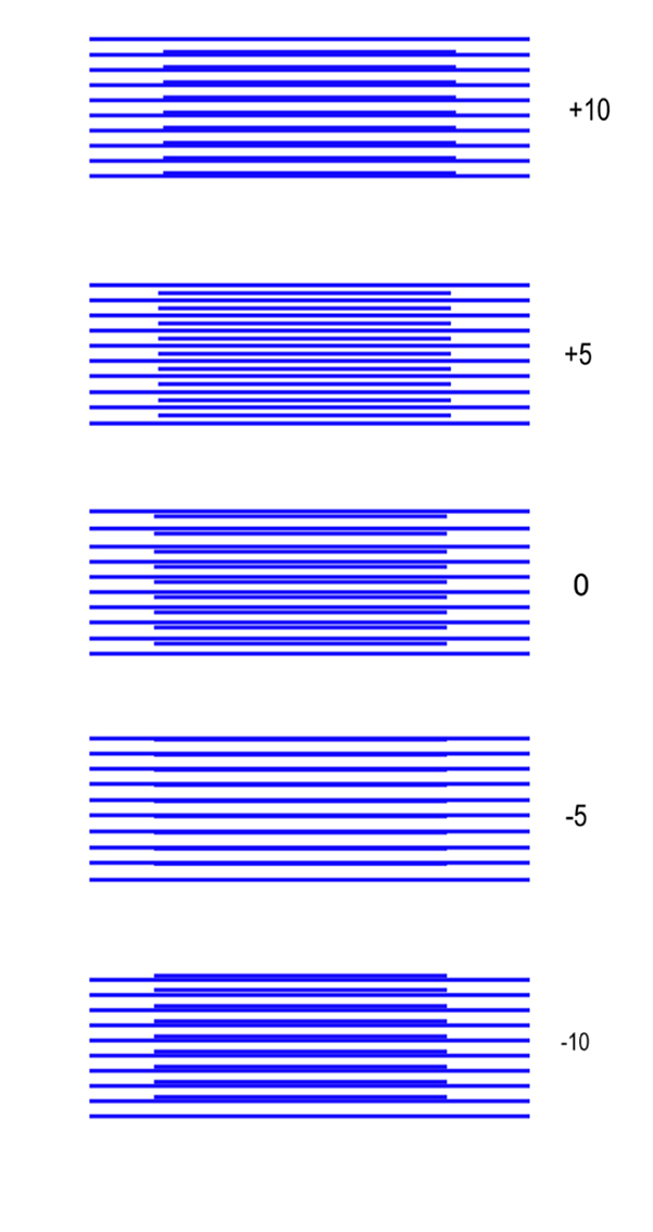
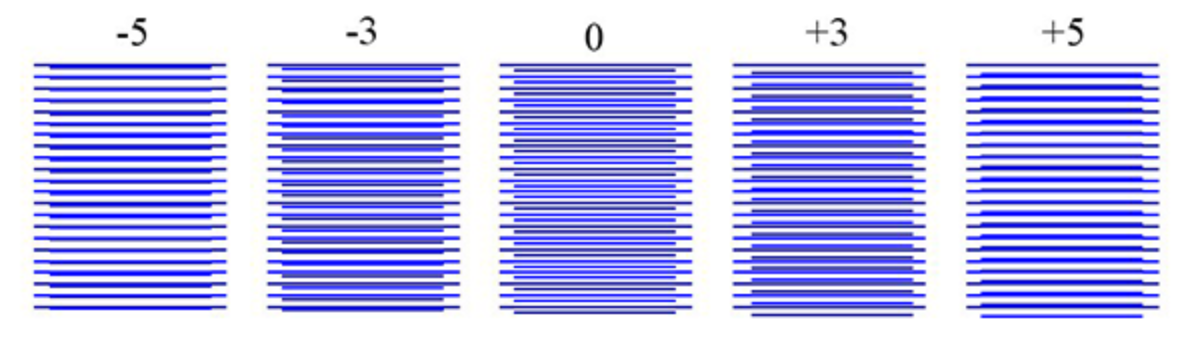
- Coarse adjustment pattern
Perform the adjustment.
 Caution / 注意
Since there is a risk of the CR Unit moving to the home position if the tape of the Front Cover Open Sensor comes off during adjustment, make sure the tape is securely fixed.
- If the following screen is displayed, press [2] button.
Press the [2] button. The carriage unit moves to the maintenance position. (To not perform adjustment, press the [8] button.)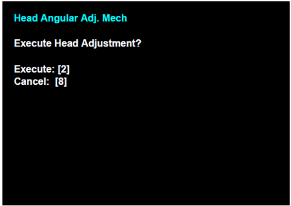
- Turn the four print head(A) fixing screws(B) counterclockwise by 90 degrees to loosen them.
Based on the adjustment value confirmed in step 7, turn the adjustment dial.
Check Point / チェックポイントThe adjustment dial adjustment method is as follows.
- Clockwise (CW): - direction(D)
- Counterclockwise (CCW): + direction(E)
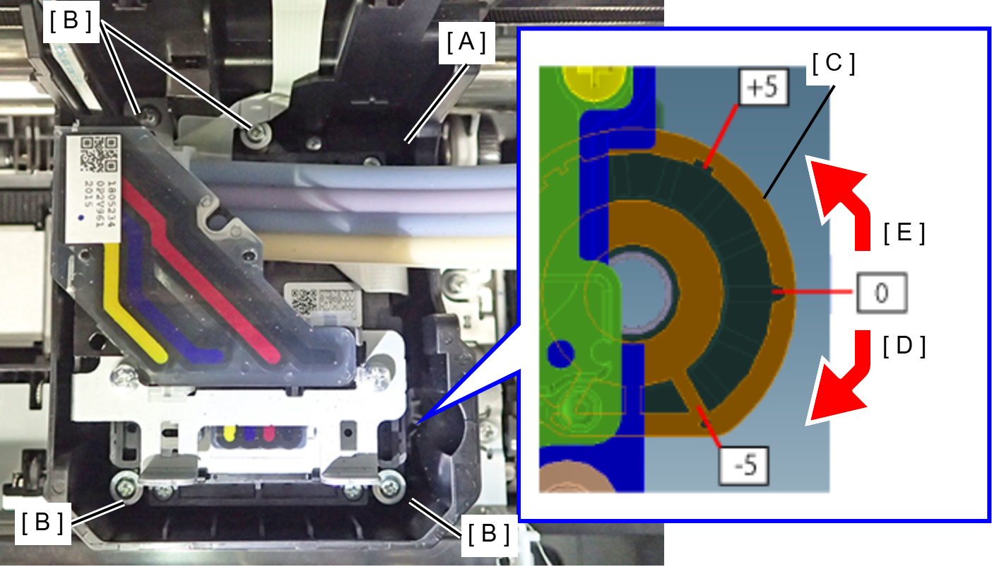
- Tighten the four fixing screws.
- A confirmation screen appears. Press the [#] button.
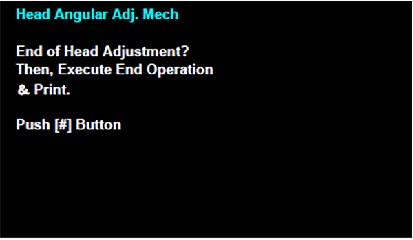
- Print the adjustment pattern again and check that the lines of the adjustment pattern of “0” are the most equal.
- Perform steps Step 8-1 to Step 8-2 and turn the adjustment dial one graduation in the deviation direction.
- Perform steps Step 8-4 to Step 8-6 to check the adjustment pattern. Repeat this procedure until the lines of the adjustment pattern of “0” become equal.
- If the following screen is displayed, press [2] button.