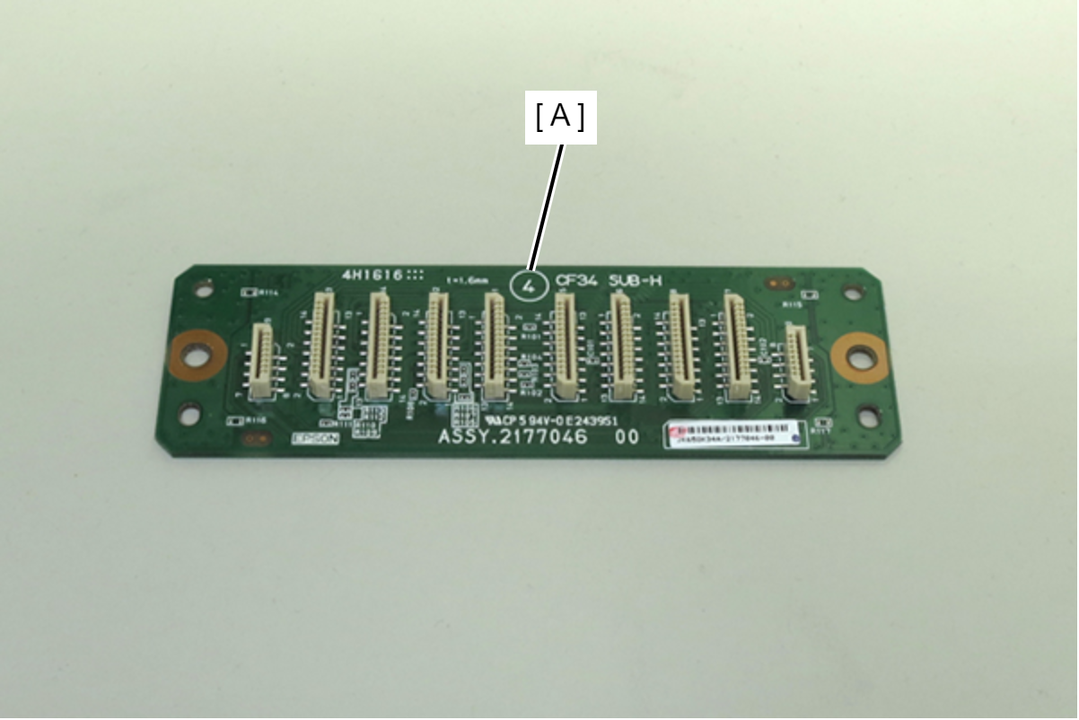
PCB Head Relay Board
- Remove one screw.
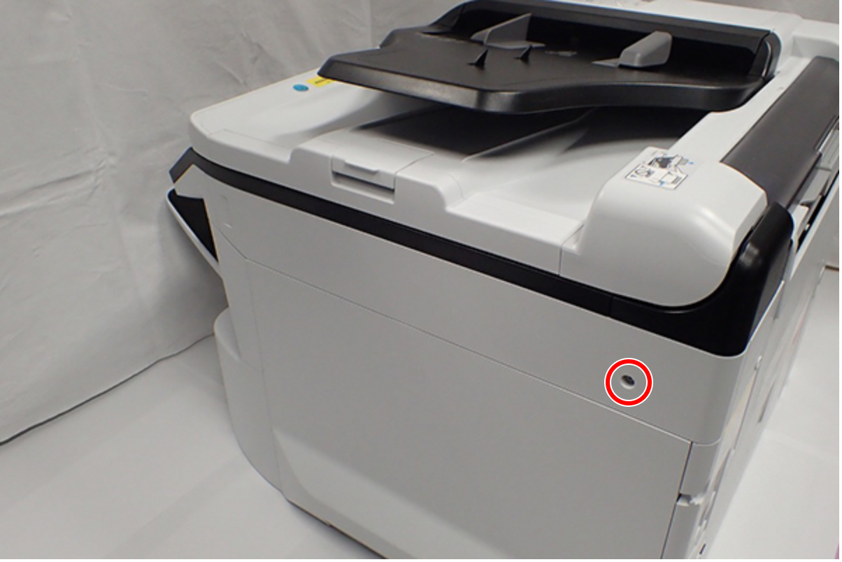
 : C.B.S-TITE-SCREW-3x8-F.ZN-3C
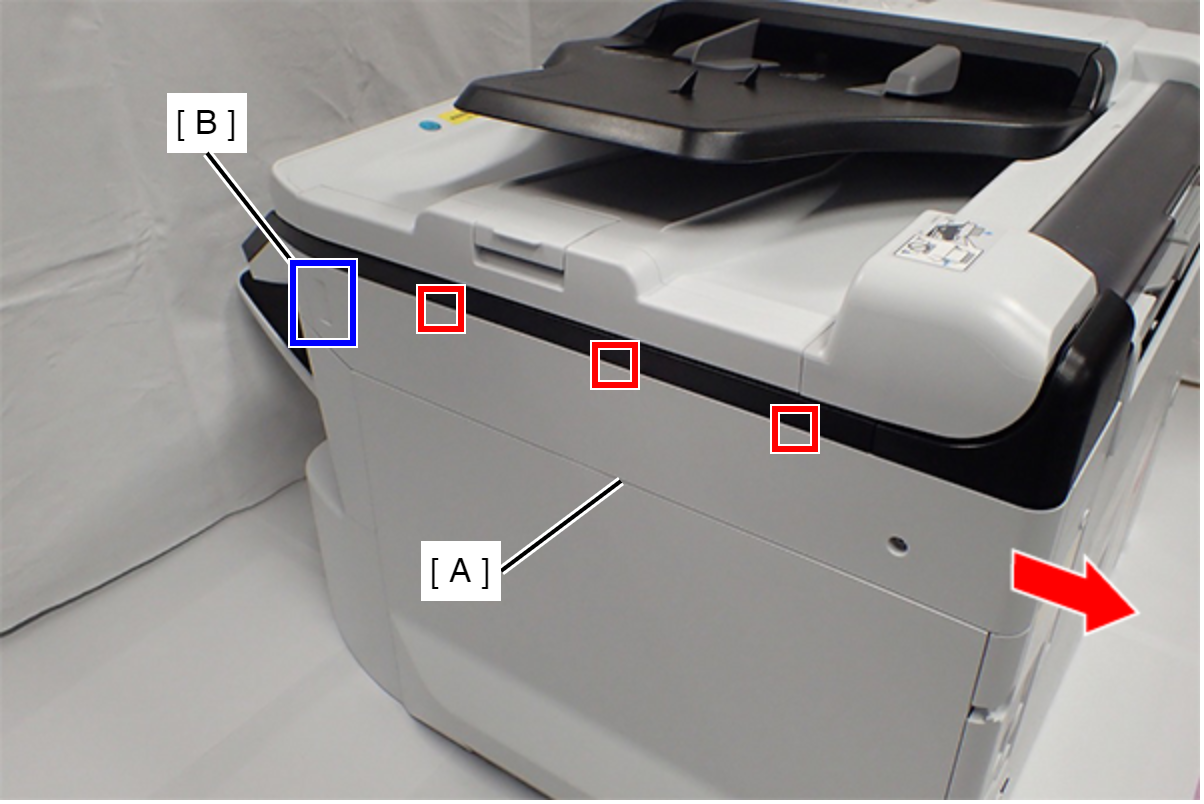
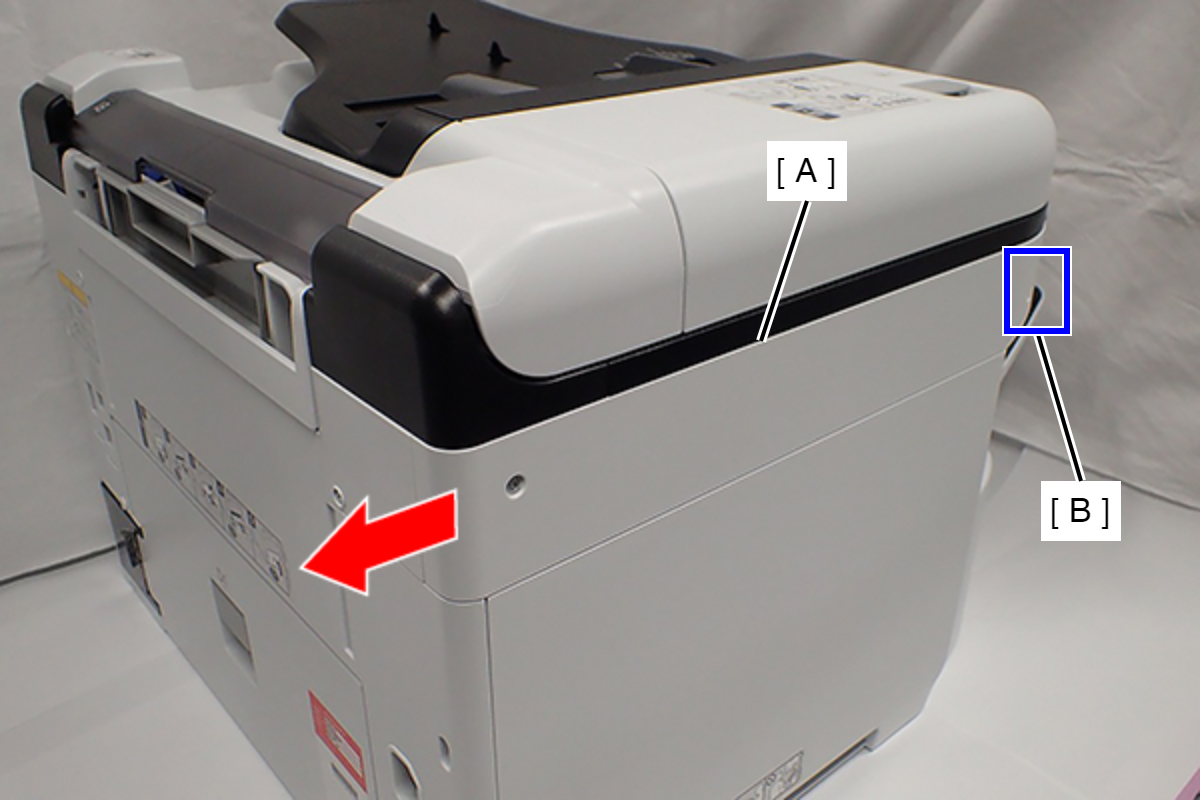
- Slide the Right SC Cover (A) while pushing the dent (B) of Right SC Cover, and release the three tabs. Remove the Right SC Cover (A).
- Remove one screw.
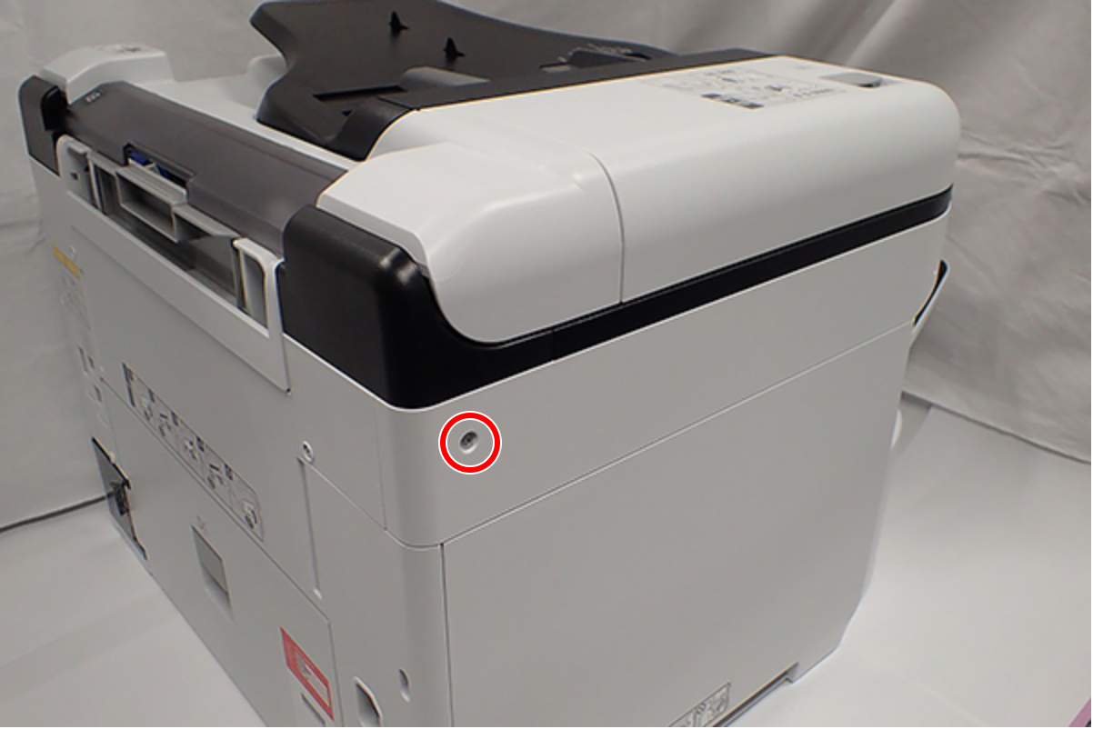
- : C.B.S-TITE-SCREW-3x8-F.ZN-3C
- Slide the Left SC Cover (A) while pushing the dent (B) of Left SC Cover, and remove it.
- Remove one screw, and remove the Lower SC Reinforcing Plate (A).
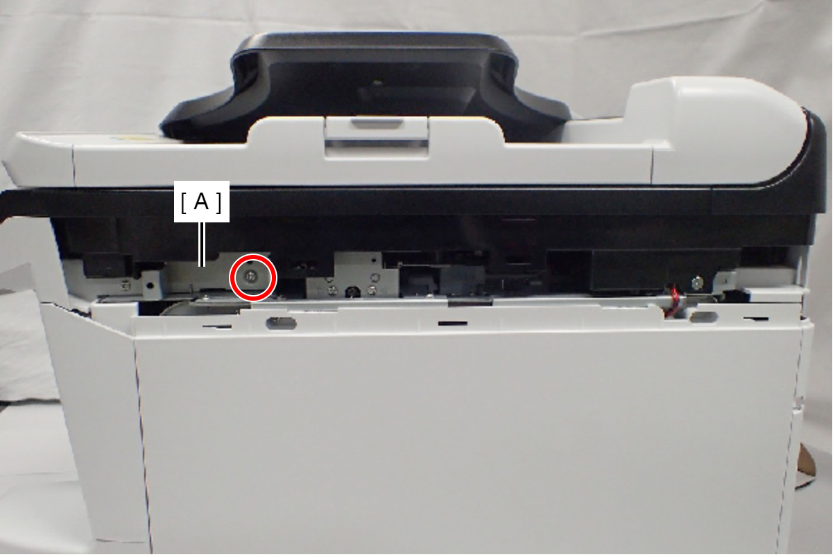
- : C.B.S-TITE-SCREW-3x8-F.ZN-3C
- Reattach the Lower SC Reinforcing Plate (A) in its portrait orientation, then secure it with the screw.
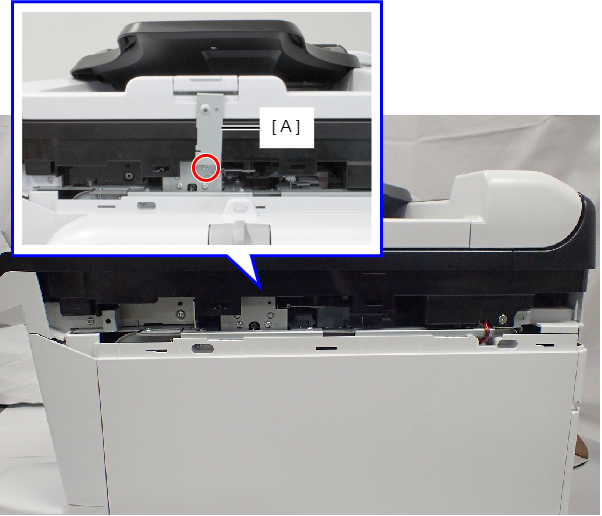
- : C.B.S-TITE-SCREW-3x8-F.ZN-3C
- Remove the screw.
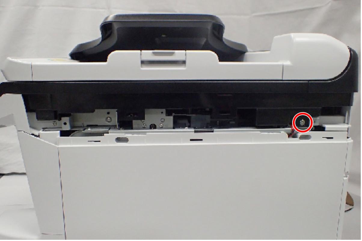
- : C.SHOULDER S-TITE,3X5
- Open the ADF/SCN Unit (A).
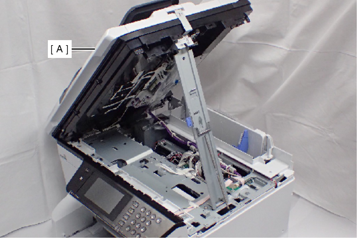
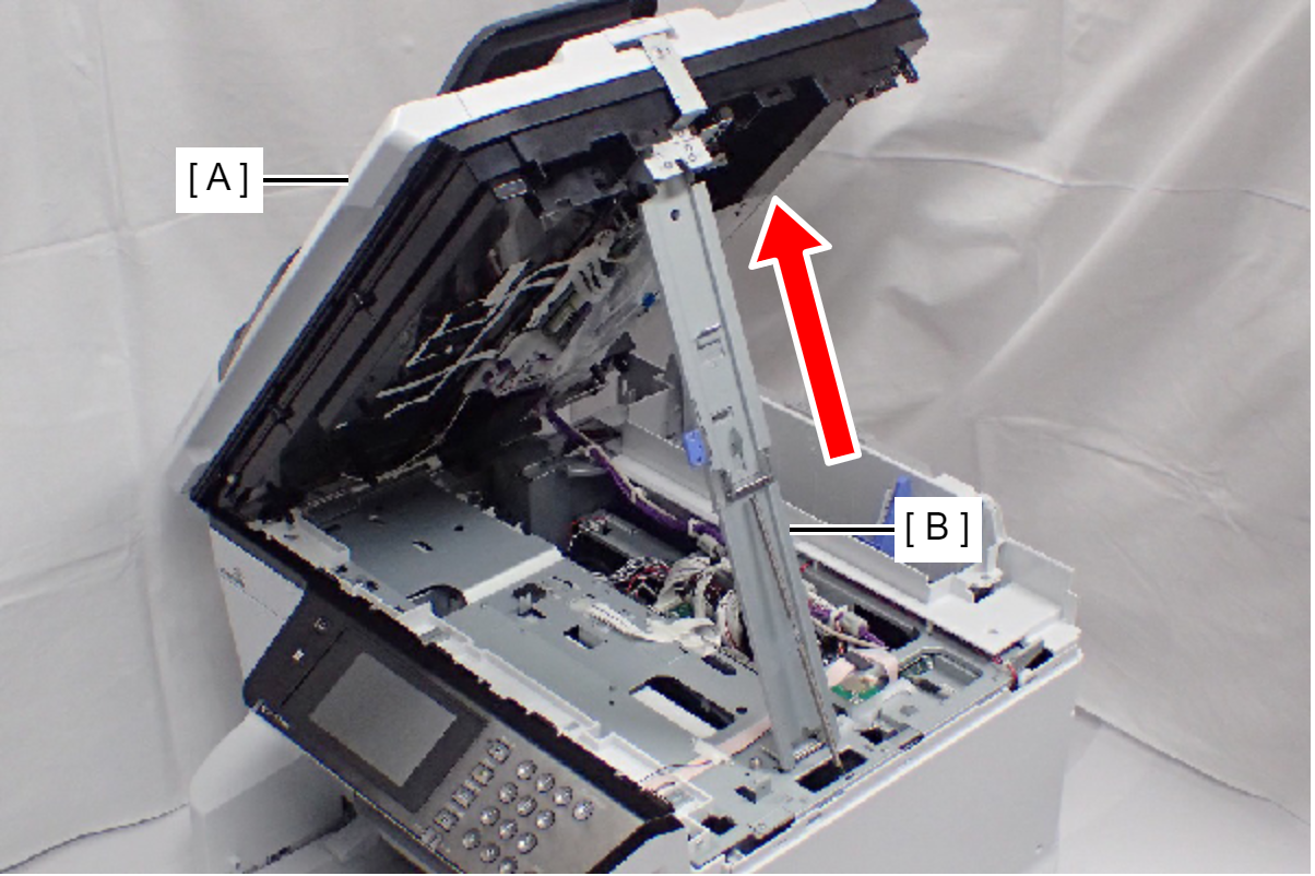
- Open the ADF/SCN Unit (A) and extend the support stand (B) as far as it goes, then support the ADF/SCN Unit with the support stand.
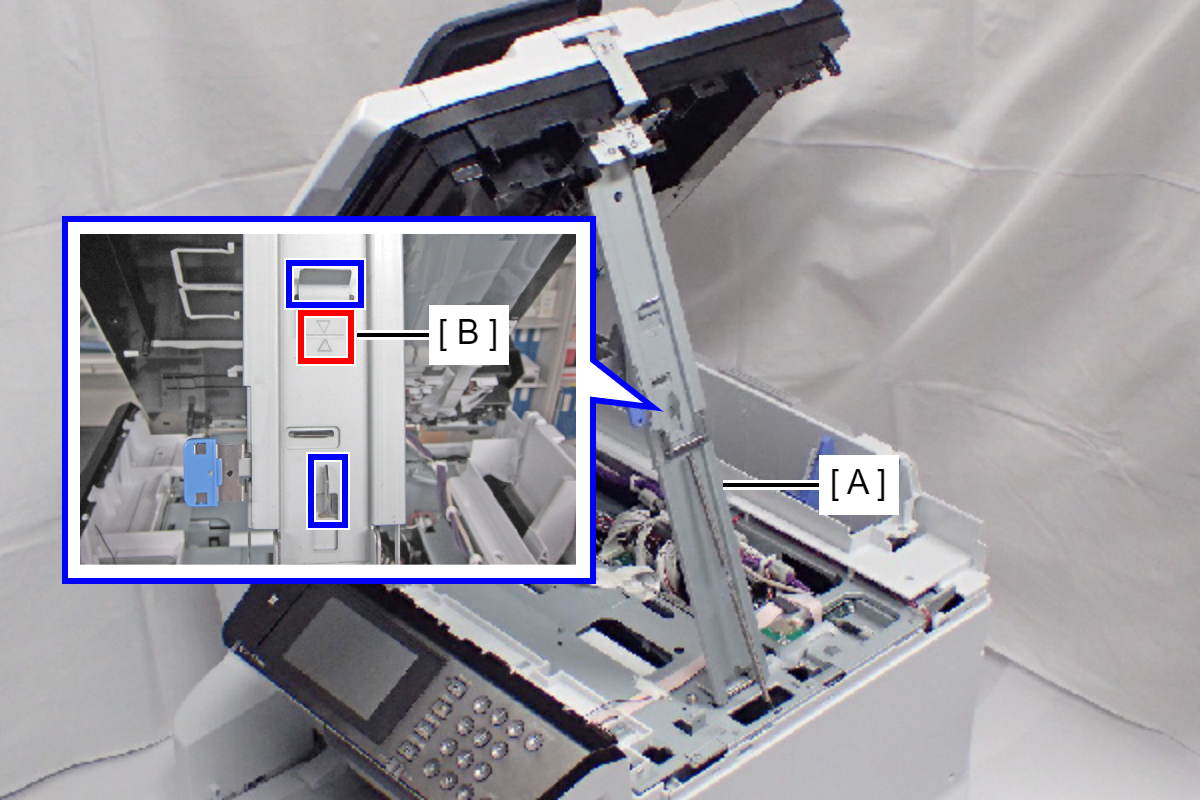
 Caution / 注意
Make sure that the support stand (A) is fixed with the two hooks, and the two triangle marks (B) face to each other.
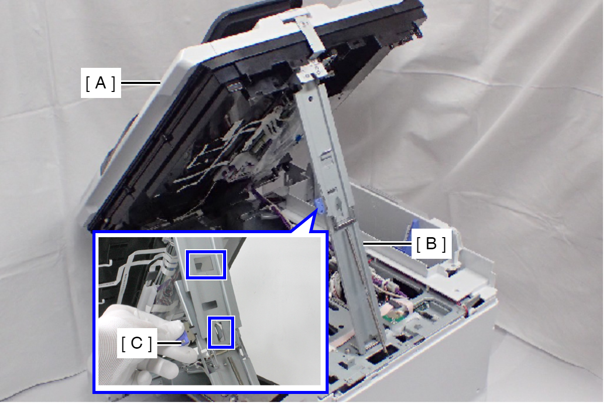
 Check Point / チェックポイント
When closing the ADF/SCN Unit (A), press the switch (C) on the ADF/SCN support stand (B) and hold up the ADF/SCN Unit to disengage the two hooks, then fold the ADF/SCN support stand.
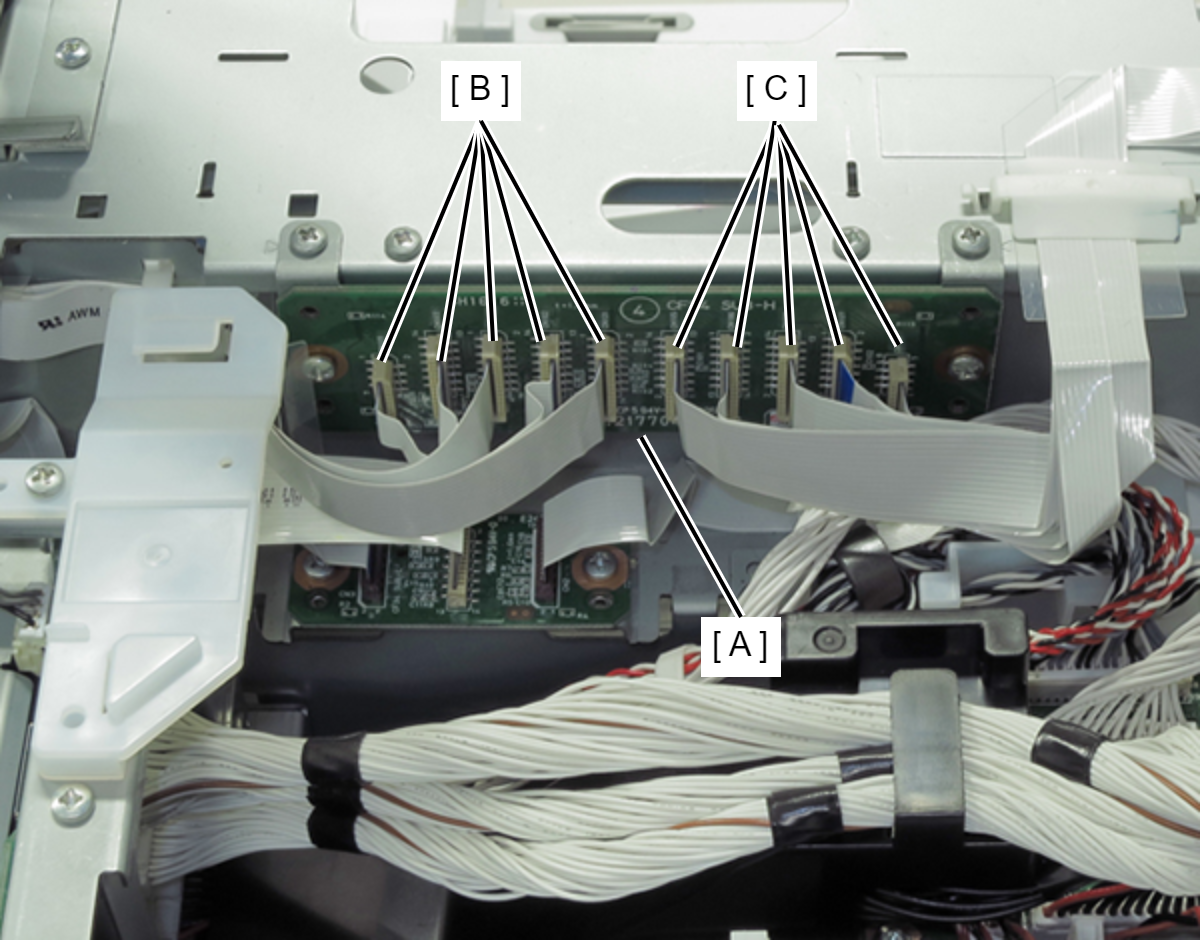
- Disconnect the five Head FFCs (C) and five Head Relay FFCs (B) from PCB Head Relay Board (A).
- Remove the two screws, then remove the PCB Head Relay Board (with Mounting Plate) (A).
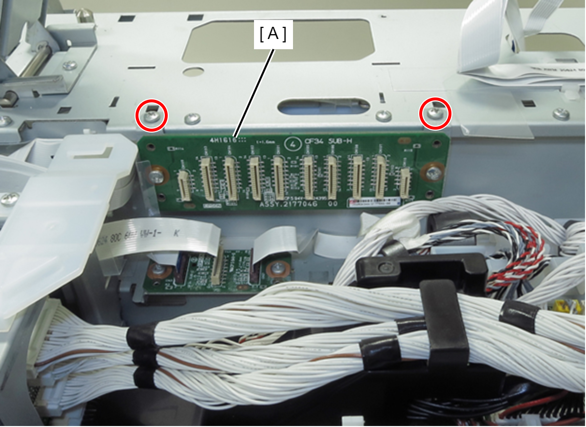
- : C.B.S-TITE-SCREW-3x8-F.ZN-3C
- Remove the two screws, then remove the two Mounting Plates (B) from the PCB Head Relay Board (A).
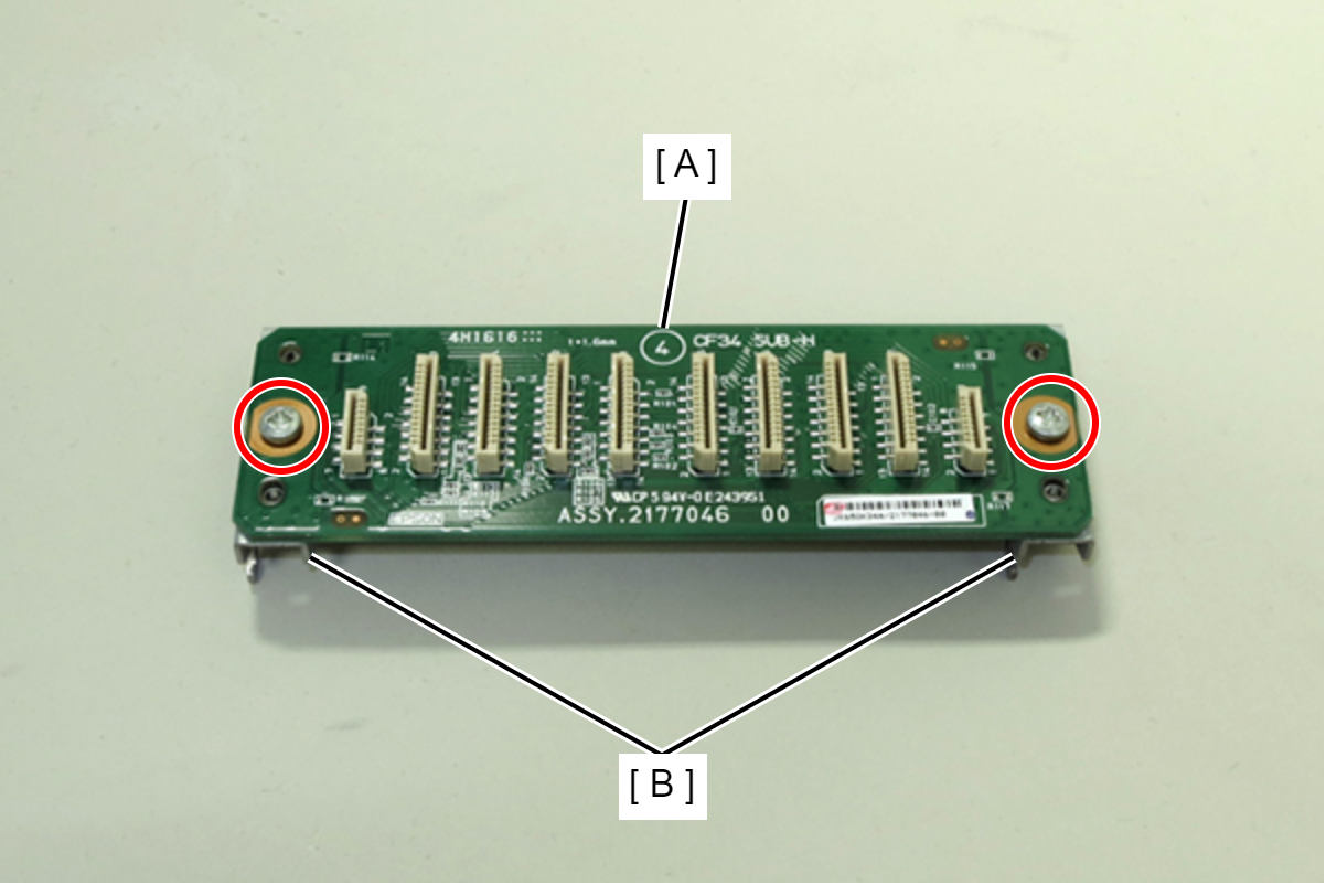
- : C.B.S-TITE-SCREW-3x8-F.ZN-3C
- Remove the PCB Head Relay Board (A).