Ink Supply Mechanism
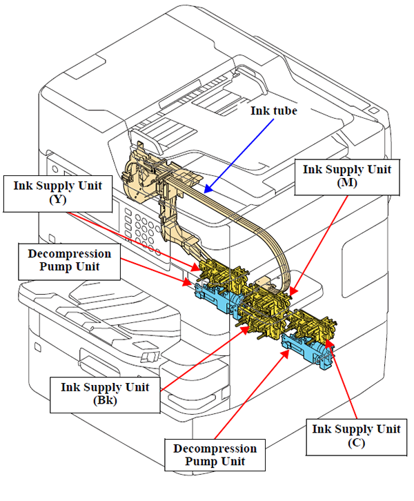
The ink supply mechanism consists of the Decompress Pump Unit and the Ink Supply Unit that is composed of the Ink Supply Tube, Diaphragm Pump*1, Buffer, and Ink Cartridge Holder.
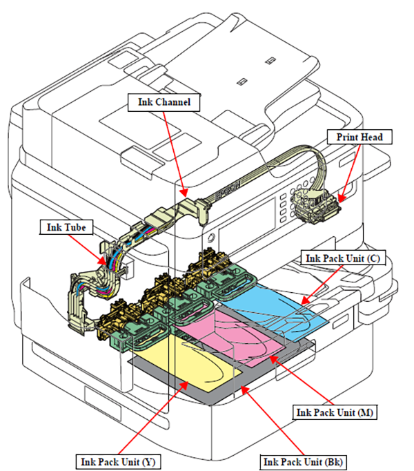
WF-C878Ra/WF-C878R mounts the Ink Pack Unit instead of ink cartridges, and ink is supplied through the ink tube to the Ink Supply Unit from the large capacity ink pack installed in the Ink Pack Unit.
According to the quantity of ink discharged from the Print Head, ink is sucked from the ink cartridges/ink packs by the Decompress Pump Unit, Diaphragm Pump and Buffer. The ink path from the Buffer through the ink tube to the self-sealing valve in the Print Head is always kept pressurized even after the power is turned off by the check valves and the Diaphragm Pump. Therefore, ink can be supplied stably during high-volume printing.
*1: The diaphragm pump is a pump equipped with a diaphragm and check valves in both input and output sides. Up-and-down movements of the diaphragms change volume of the pump, and this causes ink to be sucked or ejected.
Operating principles
In the case of WF-C878Ra/WF-C878R, ink supply becomes ready by installing the ink pack into the Ink Pack Unit. The Ink Pack Unit also mounts the CR Contact Module.
The diaphragm is operated when the Decompress Pump Unit reduces the pressure inside the Diaphragm Pump, and it sucks ink from the ink cartridges/ink packs Ink is supplied through the Buffer and ink tube to the Print Head.
WF-C878Ra/WF-C878R feature two Decompress Pumps and connected with the two Diaphragm Pumps in the ink path. These two Decompress Pumps and Diaphragm Pumps supply sufficient ink needed for the quantity of the Print Head's ink discharge in high speed printing with high image quality.
Ink Pack Unit
The WF-C878Ra/WF-C878R uses large-capacity Ink Packs. The Ink Pack Unit for mounting the Ink Packs is provided inside the printer.
The Ink Pack Unit is connected to the Print Head by the Ink Tubes via the Ink Supply Unit, and the ink in the Ink Packs is supplied to the Print Head.
The amount of remaining ink is monitored by the Ink End Sensors and the ink consumption counter of the firmware. The Ink End Sensors are mounted inside the ink packs and the Ink Supply Unit.
Therefore, if the ink channel between the Ink Pack Unit and Print Head is blocked, the error (ink end) occurs.
Also, Piston Valves are provided at the connections of the Ink Tubes, Ink Supply Unit and Print Head. These valves are designed to close when the Ink Tubes have been removed. This structure prevents ink from dripping, for example, from the Ink Tubes.
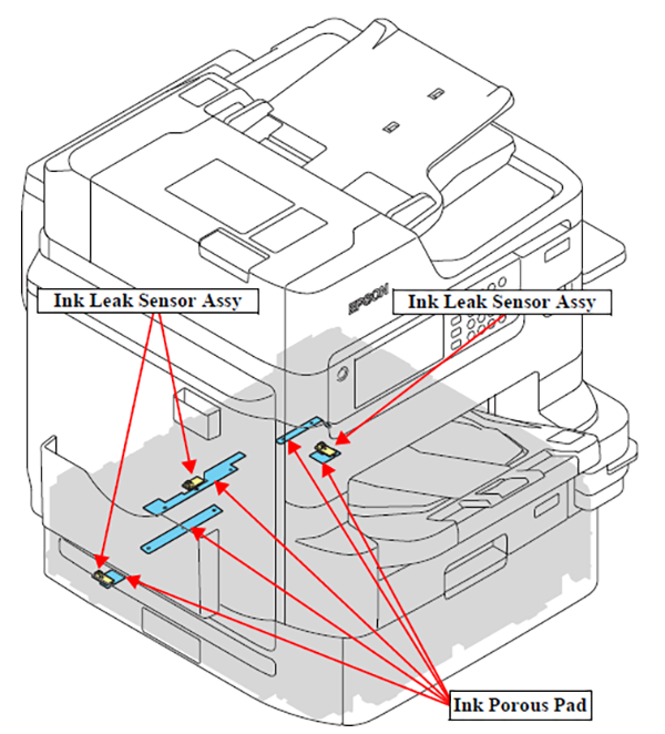
Ink leak detection function
A sensor for detecting an ink leak is provided in this product in order to enable the quick detection of an ink leak when an ink leak occurs from the ink supply path due to an abnormality in the product.
The Ink Leak Sensor Assy is provided inside the Ink Pack Unit, and detects an ink leak by the adherence of ink on it (Ink Porous Pad, 1) when an ink leak occurs. It also generates an ink leak error in the printer.