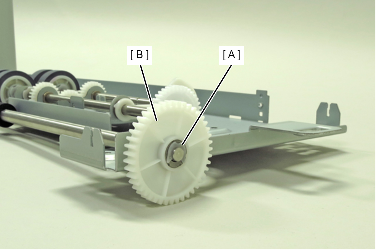
Spur Gear (with E-ring)
- Remove the Printer Main Unit from Option Cassette Unit (A).
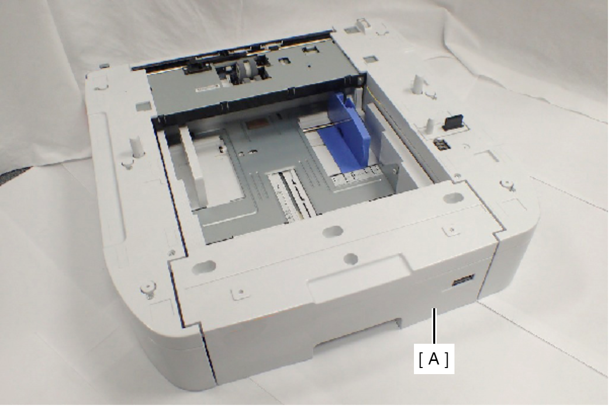
- Remove the four screws, then remove the Option Right Cover (A).
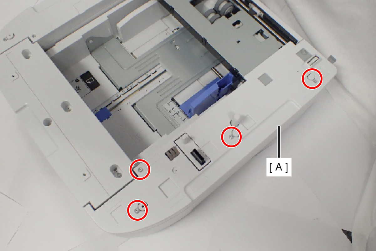
 : C.B.P-TITE-SCREW-3x10-F.ZN-3C
- Remove the four screws, then remove the Option Left Cover (A).
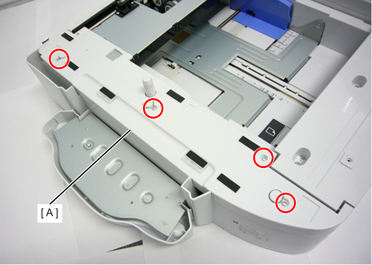
- : C.B.P-TITE-SCREW-3x10-F.ZN-3C
- Remove the two screws, then remove the Option Rear Fitting Frame (A).
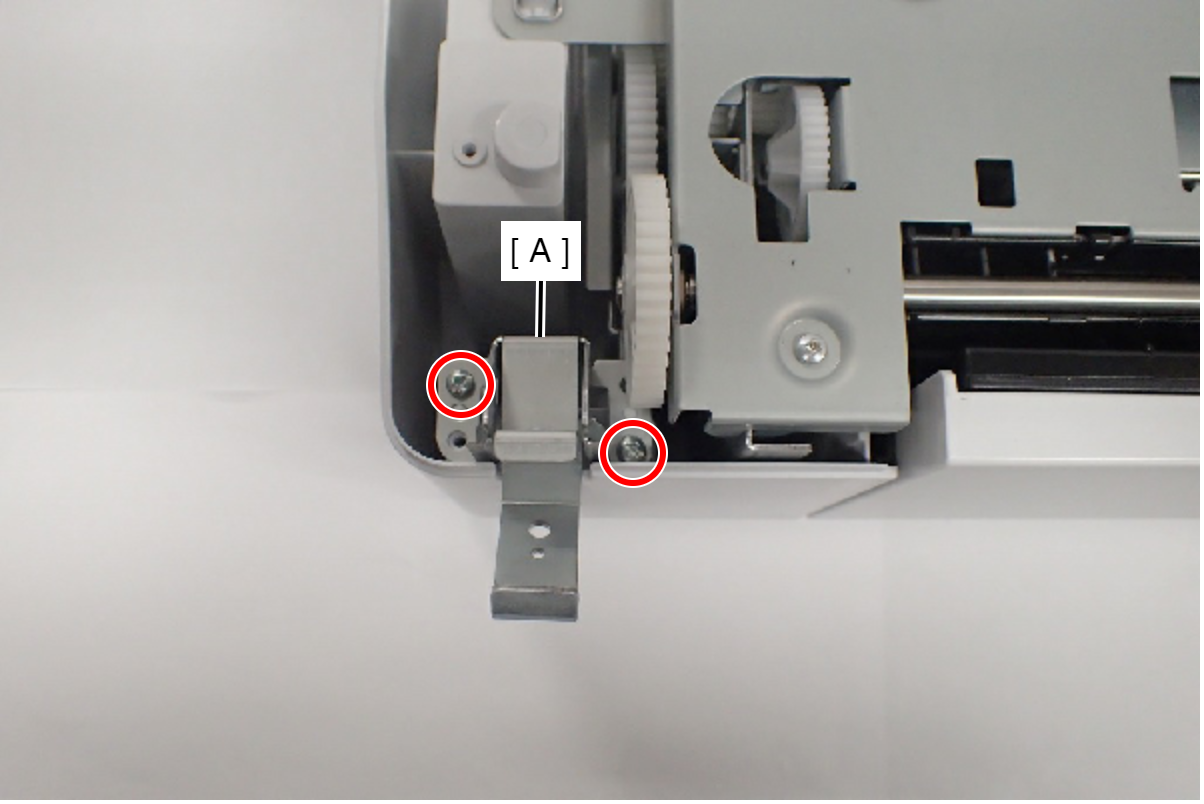
- : C.B.P-TITE-SCREW-3x10-F.ZN-3C
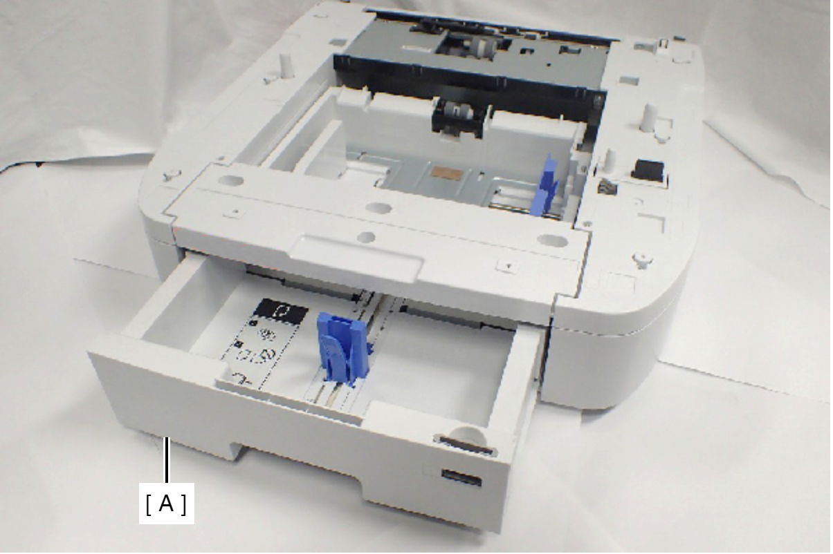
- Remove the Option Paper Cassette (A).
- Remove the two screws, and remove the Grounding Frame Assy (A).
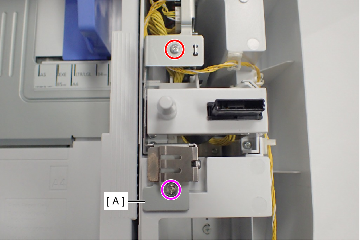
- : C.B.S-TITE-SCREW-3x6-F.ZN-3C
 : C.C.P-TITE-SCREW-3x8-F.ZN-3C
- Open the Option Rear Cover (A).
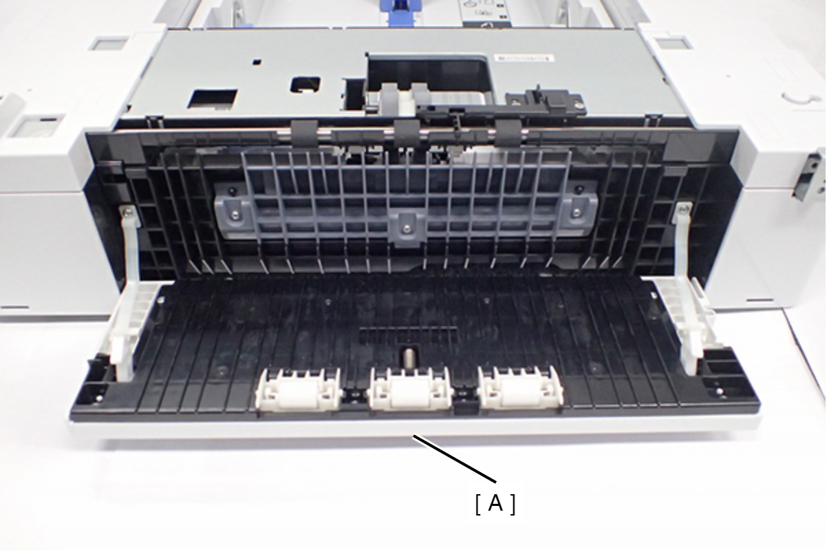
- Remove the five screws fixing the Cassette Drawers.
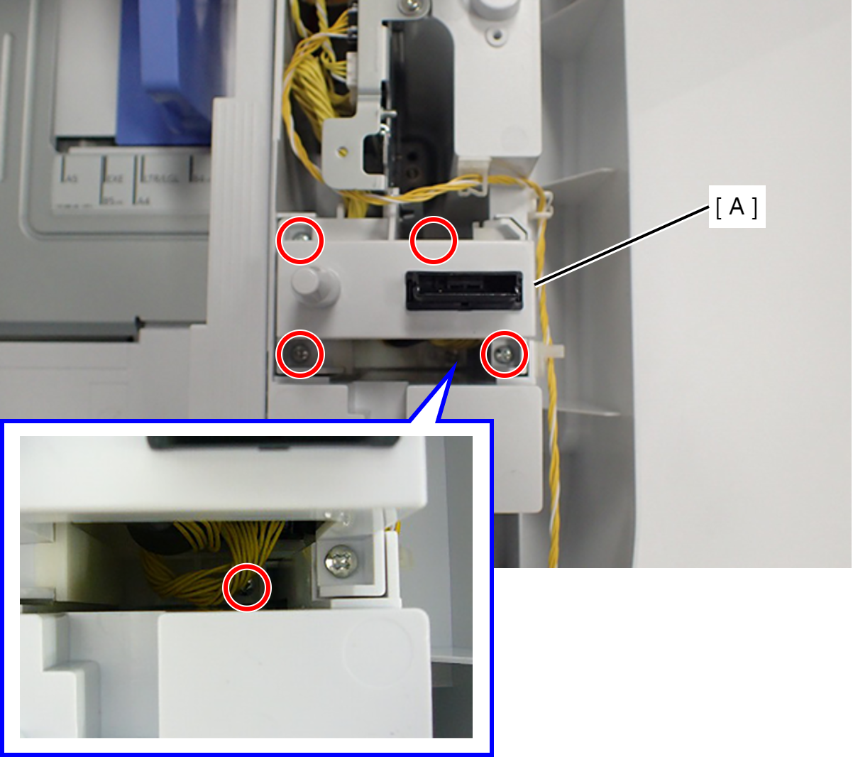
- : C.B.P-TITE-SCREW-3x10-F.ZN-3C
- Remove the five screws fixing the Option Drive Frame Assy (A).
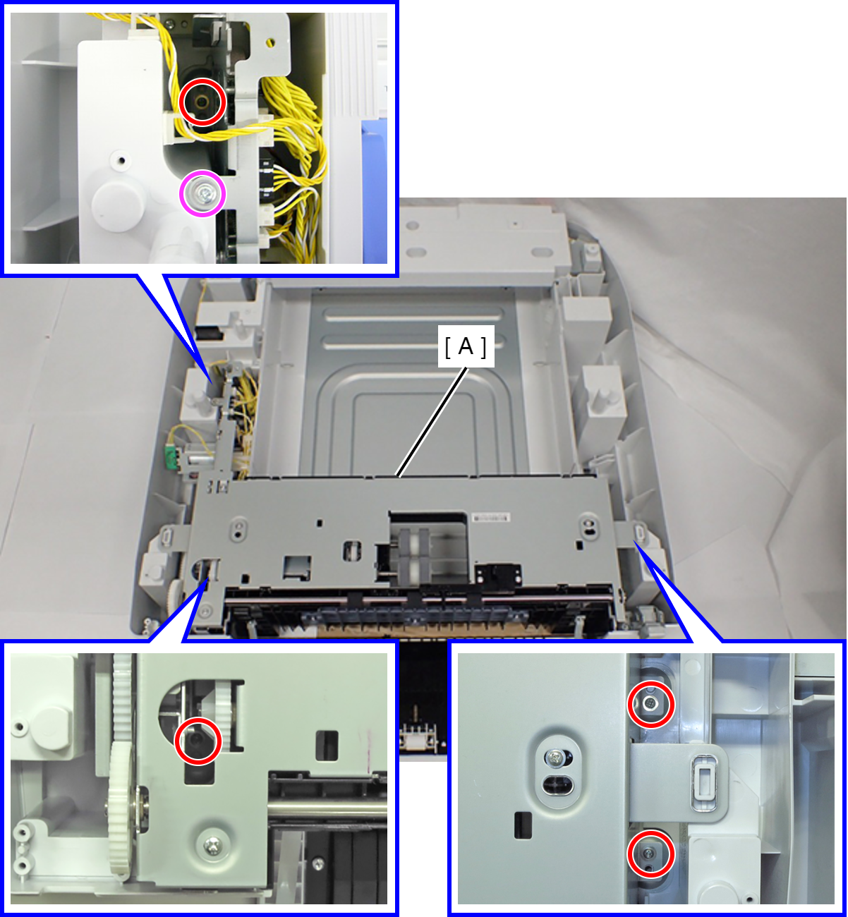
- : C.POLWAVE.D-TITE-A-SCREW-3x6-F.ZN3C
- : C.C.P-TITE-SCREW-3x8-F.ZN-3C
- Disconnect the two cables (A) from the Option Cassette Board (B).
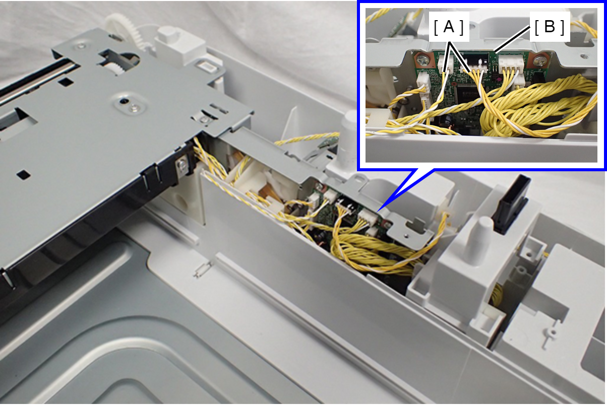
- Remove the Option Drive Frame Assy (A).
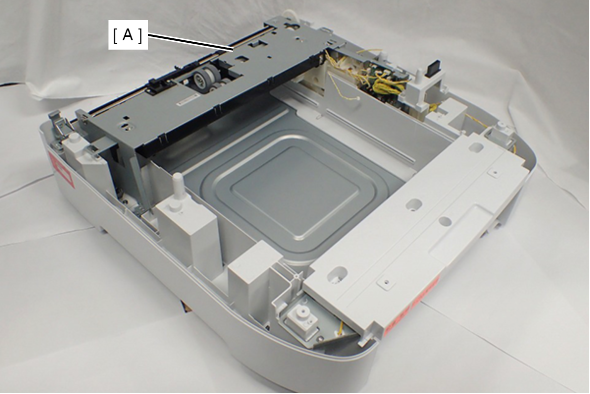
- Remove the cable from the connector (CN7, CN10) (A) of the board.
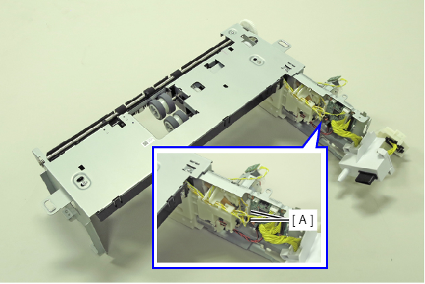
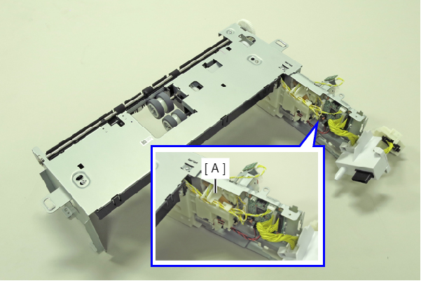
- Release the cable from the cable holder (A).
- Remove the two screws, then remove the Option Rear Frame Assy (A).
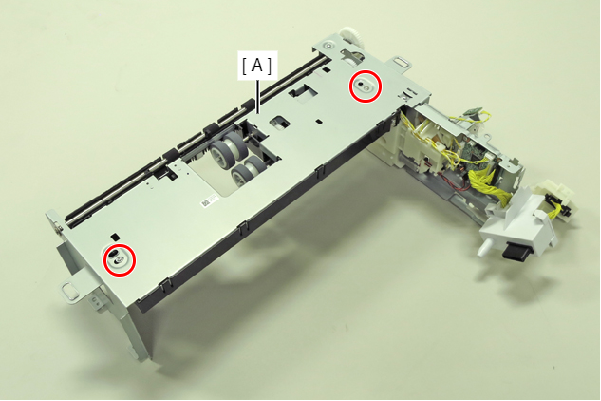
- : C.B.S-TITE-SCREW-3x6-F.ZN-3C
- Remove the two screws, then remove the Option Feed Lever Cover (A).
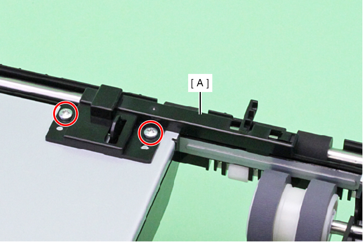
- : C.B.P-TITE-SCREW-3x8-F.ZN-3C
- Release the Option Feed Lever (A) from the holes of the cover.
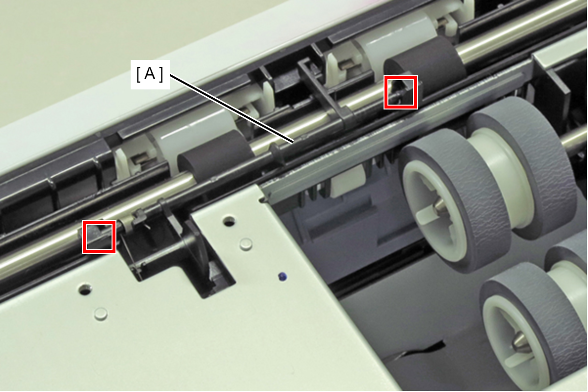
- Remove the Option Feed Lever (A) with the spring (B).
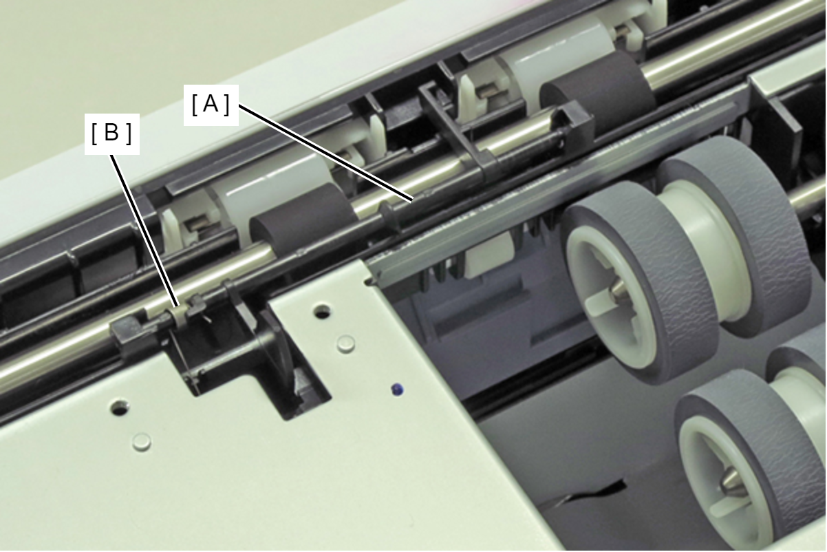
 Assembly / 組み立て
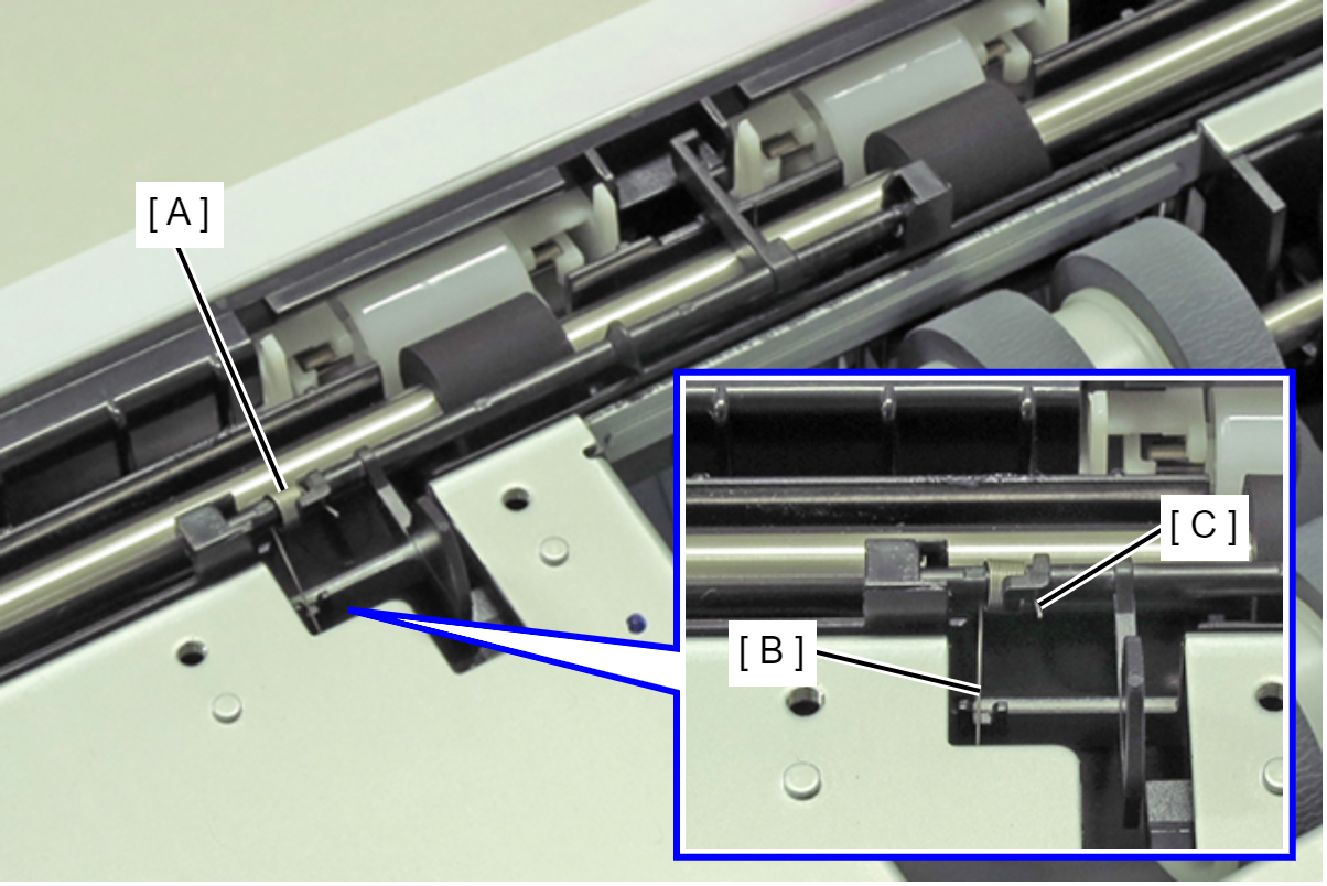
Engage long leg (B) and short leg (C) of the spring (A), and attach the spring (A).
- Remove the screw, then remove the Option Cassette Ground Plate (A).
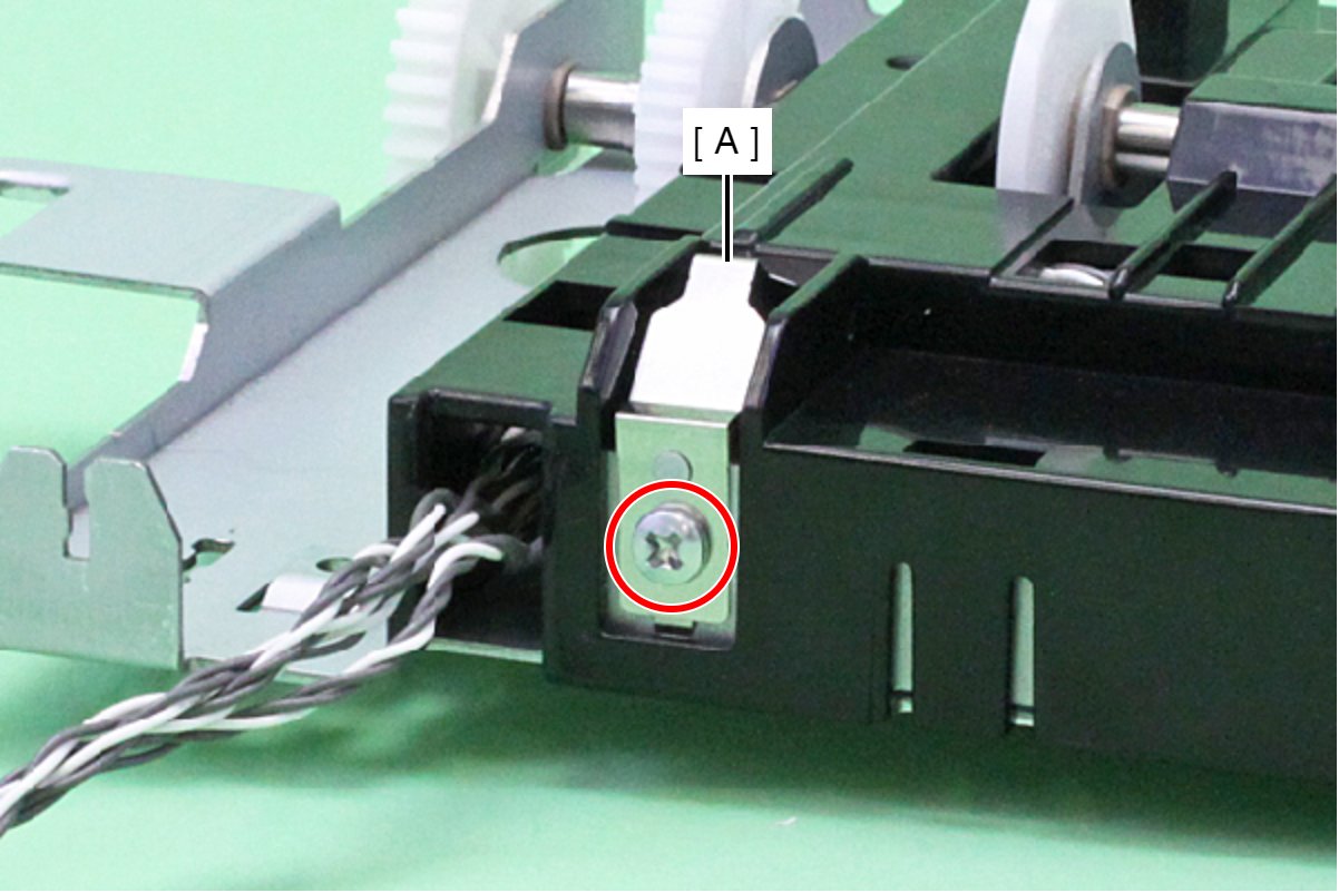
- : C.B.S-TITE-SCREW-3x6-F.ZN-3C
- Remove the two screws.
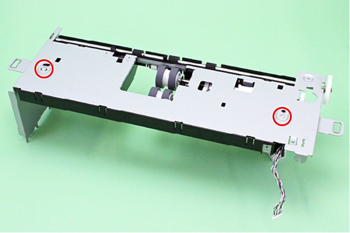
- : C.C.P-TITE-SCREW-3x8-F.ZN-3C
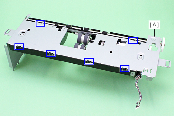
- Disengage the six hooks, then remove the Option Pickup Holder Assy (A).
- Remove the E-ring (A), then remove the Spur Gear (B).