
Lift Drive Assy
 Adjustment / 調整 Adjustment / 調整 |
When replacing this part, you need to run the menu from the service support mode before replacing it. |
- Remove one screw.
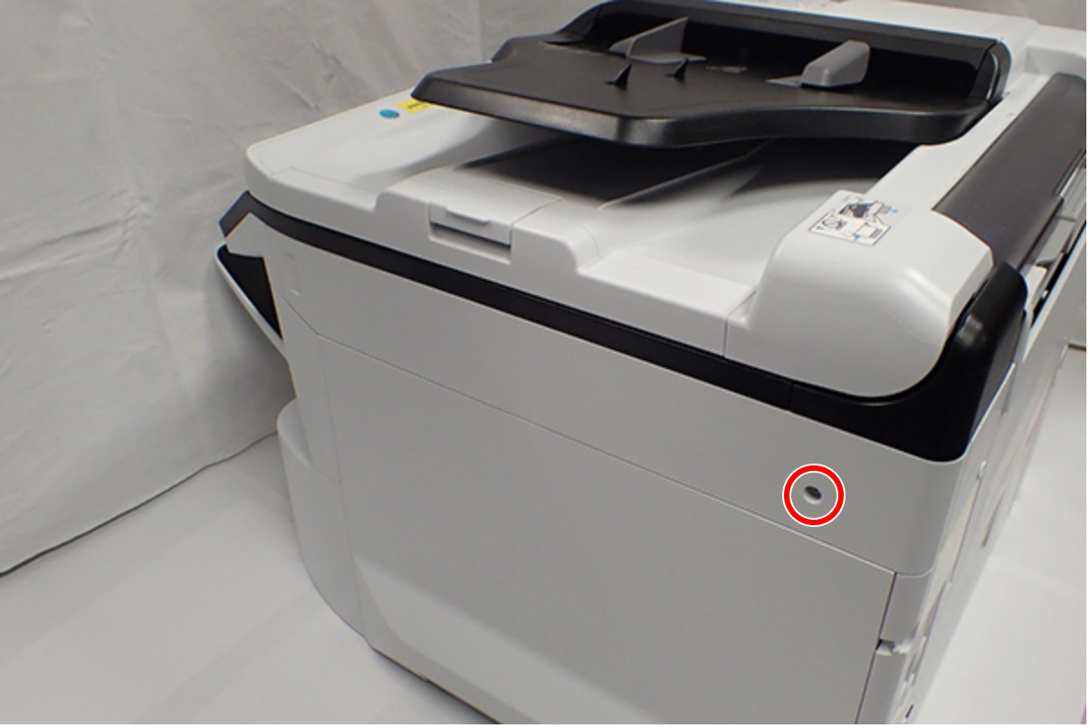
 : C.B.S-TITE-SCREW-3x8-F.ZN-3C
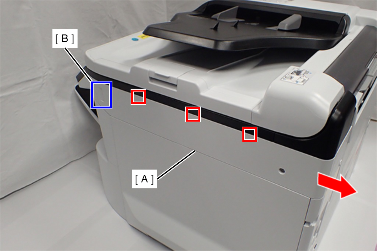
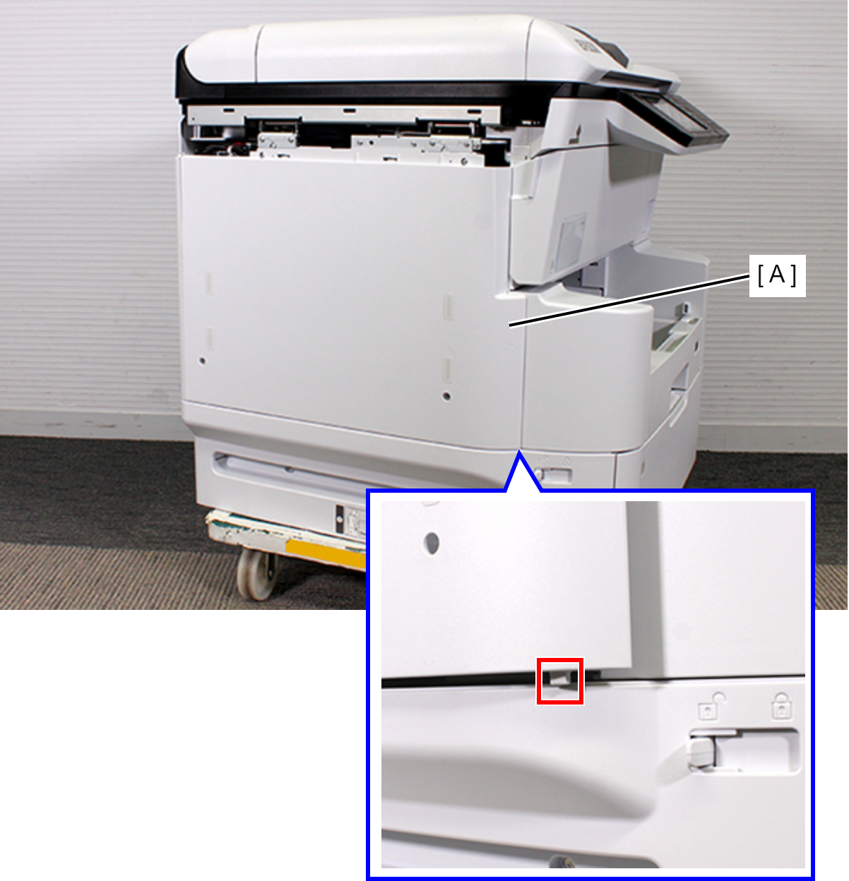
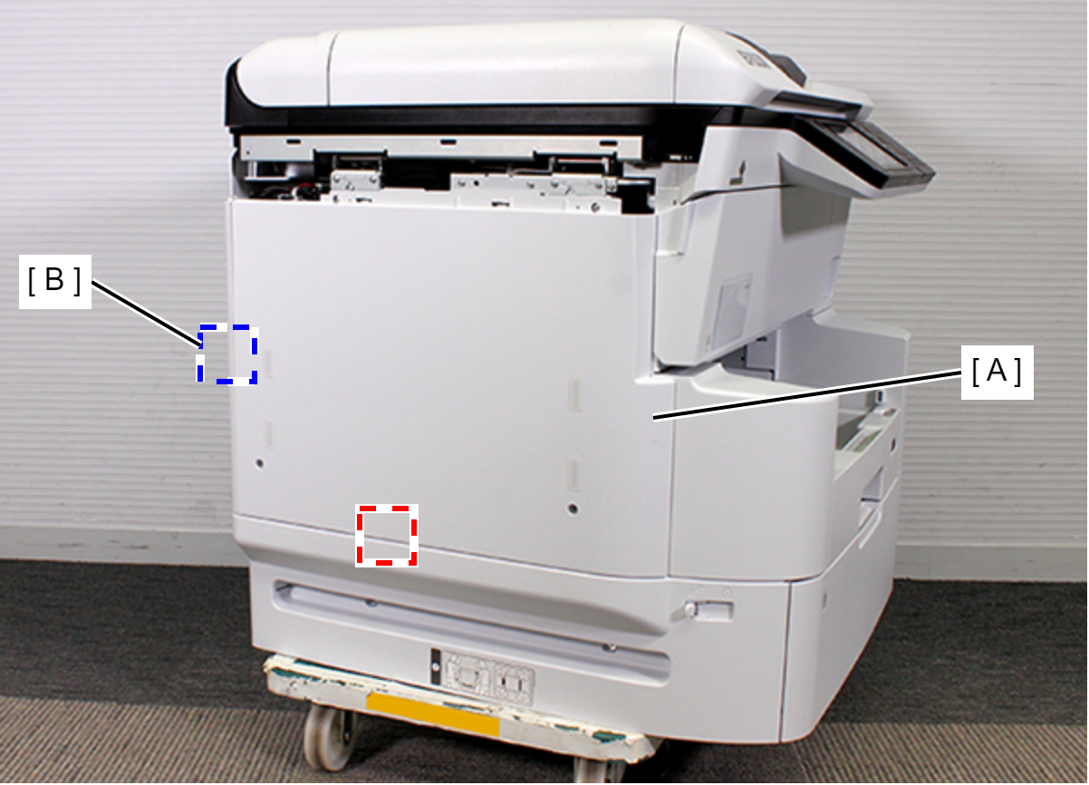
- Slide the Right SC Cover (A) while pushing the dent (B) of Right SC Cover, and release the three tabs. Remove the Right SC Cover (A).
- Remove one screw.
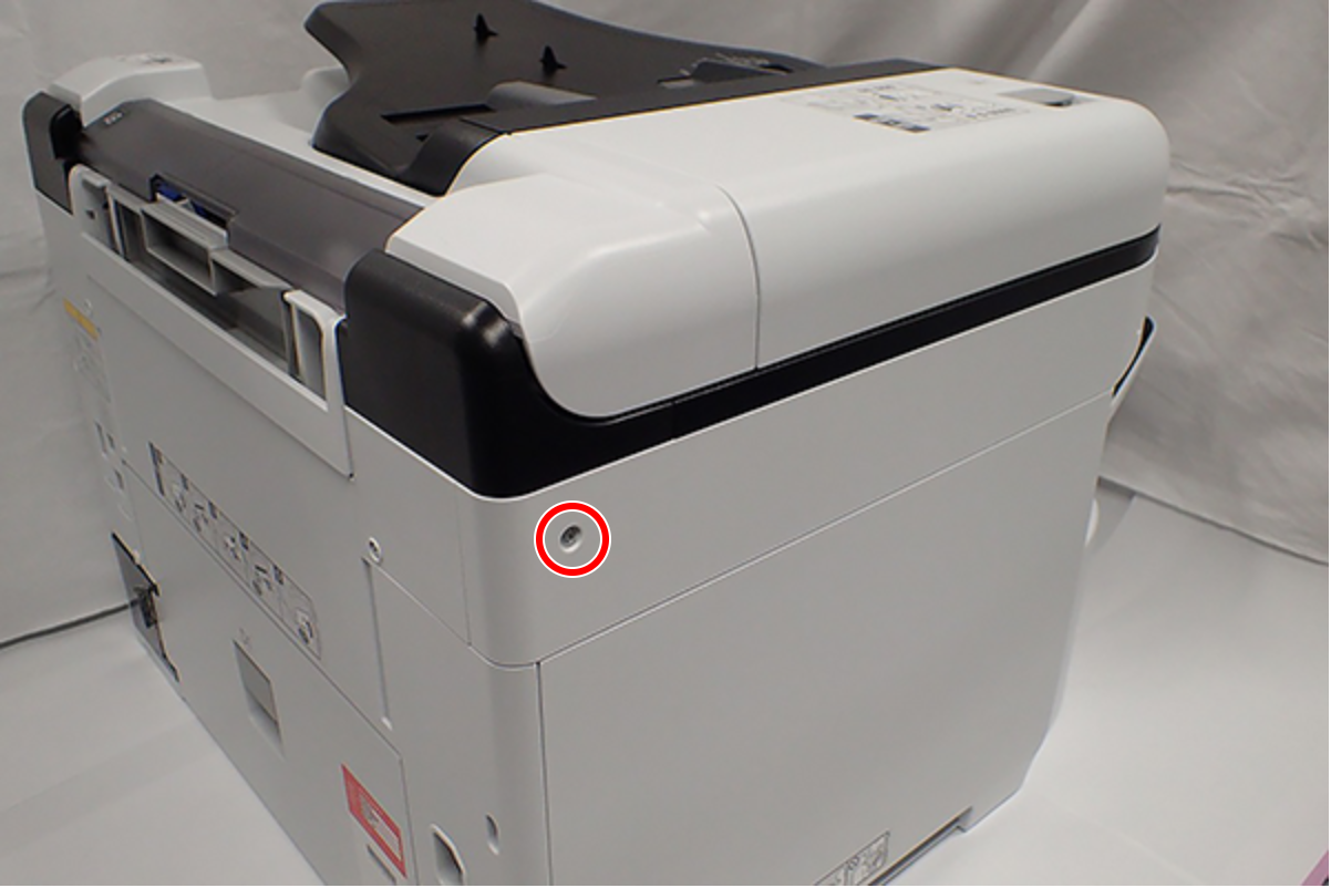
- : C.B.S-TITE-SCREW-3x8-F.ZN-3C
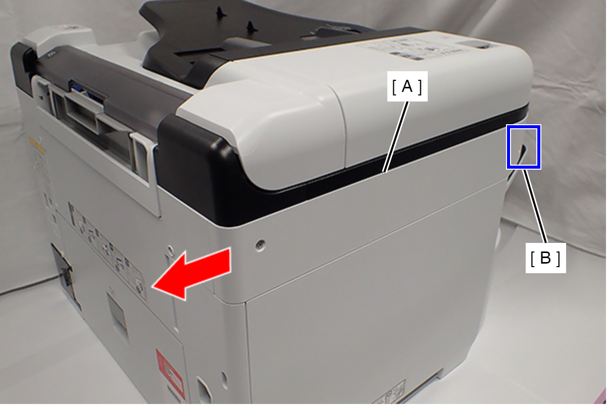
- Slide the Left SC Cover (A) while pushing the dent (B) of Left SC Cover, and remove it.
- Remove one screw, and remove the Lower SC Reinforcing Plate (A).
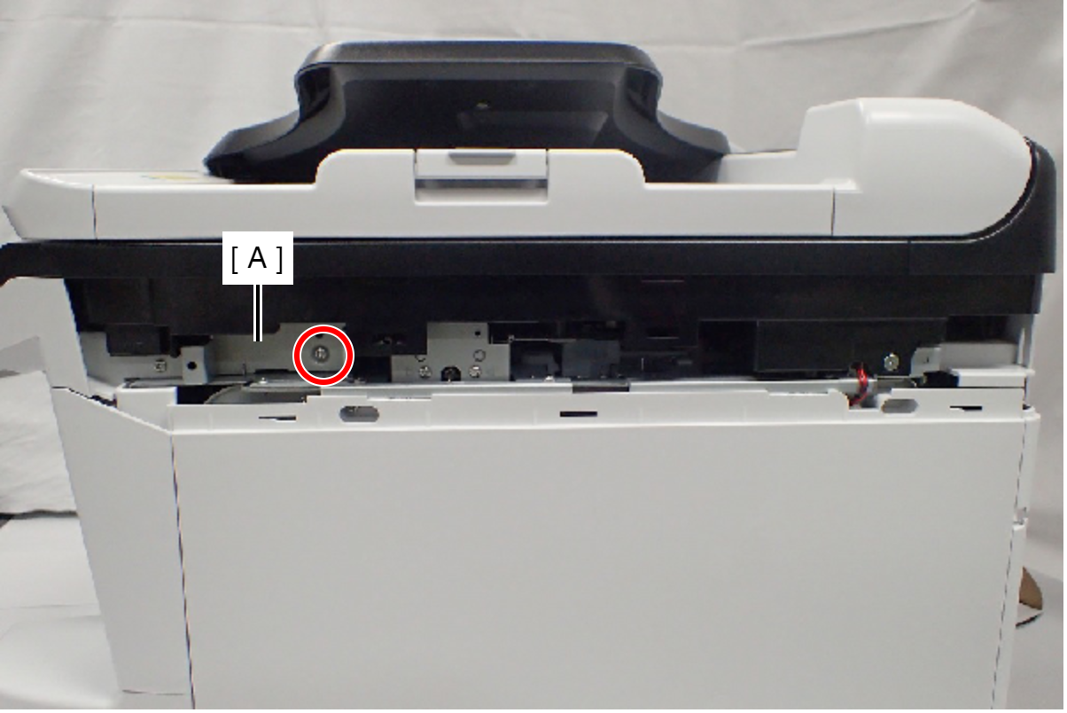
- : C.B.S-TITE-SCREW-3x8-F.ZN-3C
- Reattach the Lower SC Reinforcing Plate (A) in its portrait orientation, then secure it with the screw.
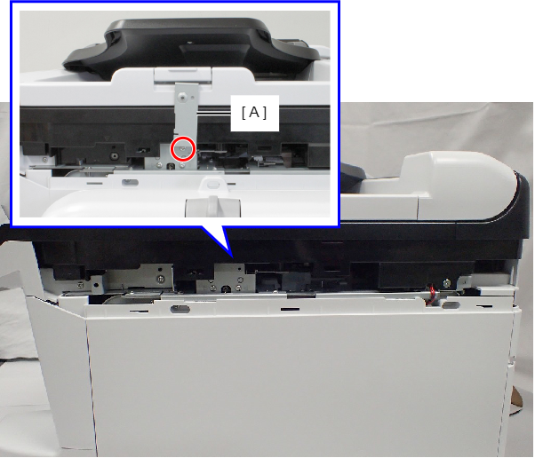
- : C.B.S-TITE-SCREW-3x8-F.ZN-3C
- Remove the screw.
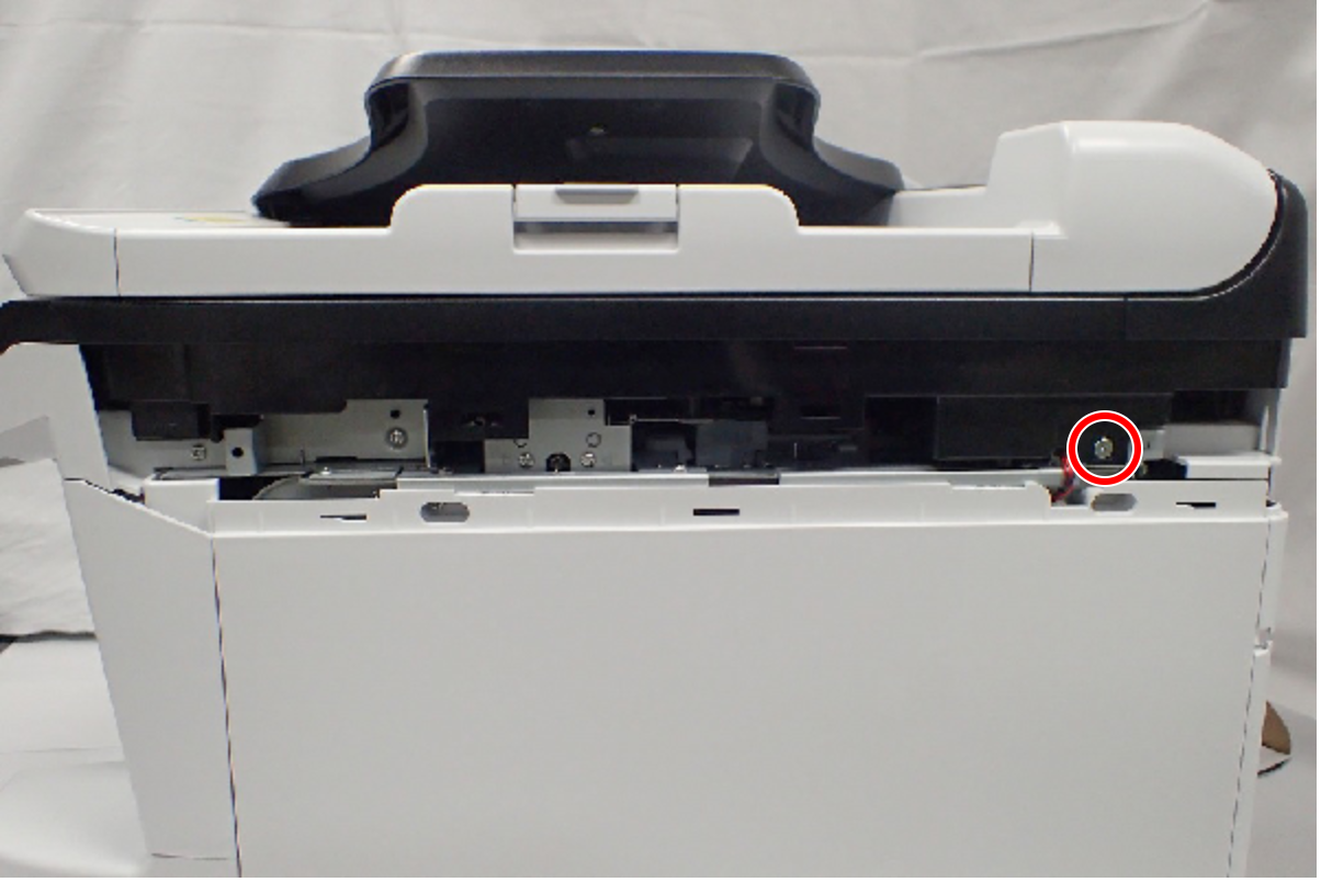
- : C.SHOULDER S-TITE,3X5
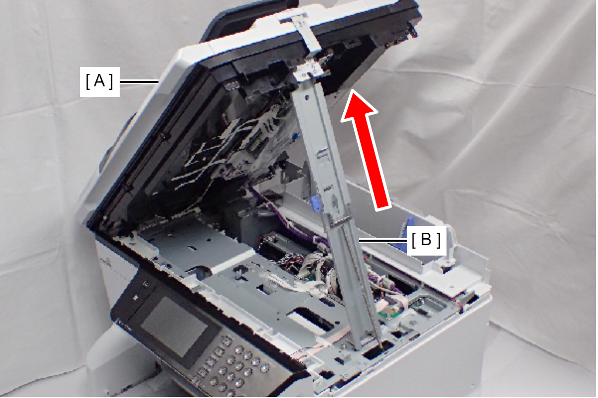
- Open the ADF/SCN Unit (A).
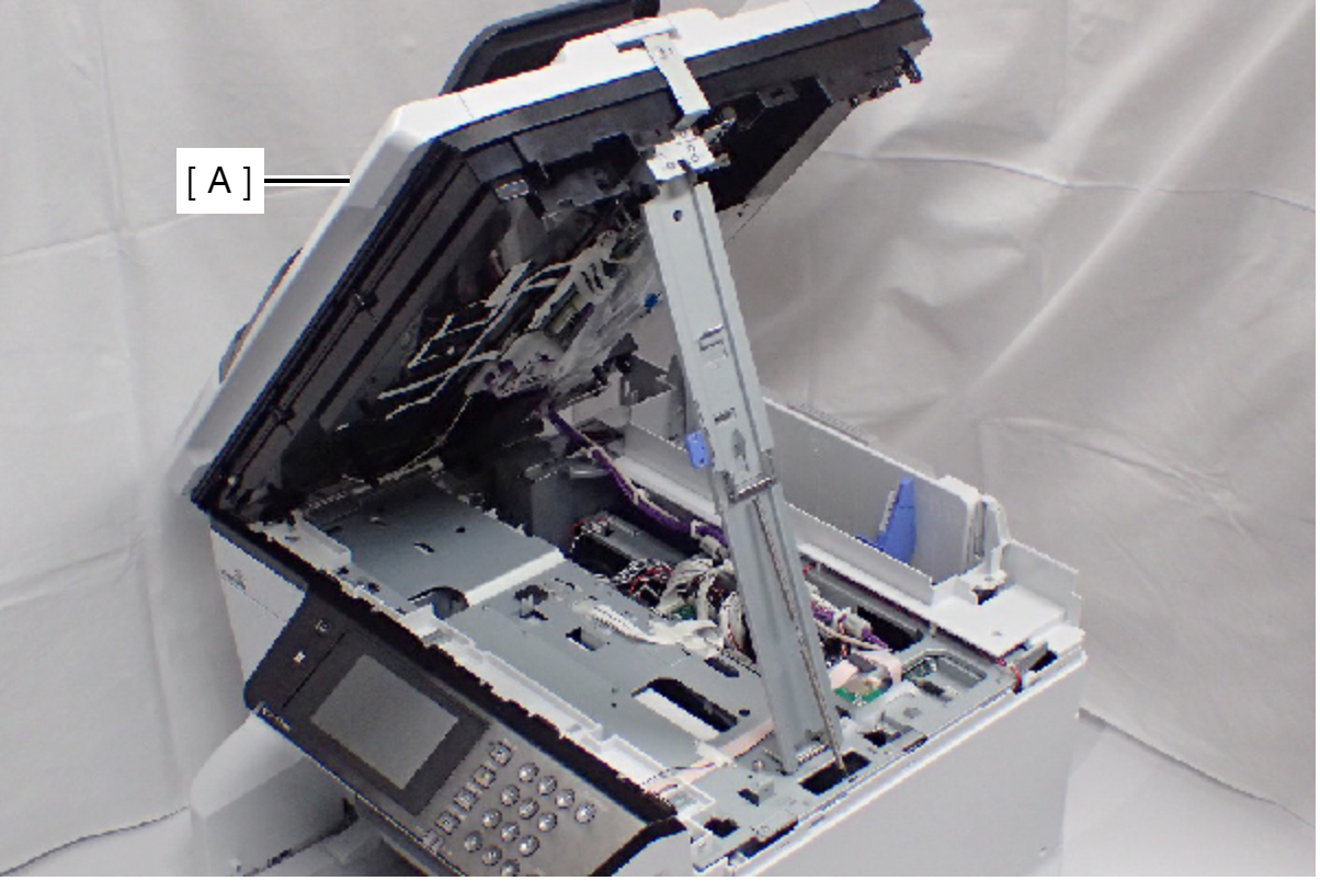
- Open the ADF/SCN Unit (A) and extend the support stand (B) as far as it goes, then support the ADF/SCN Unit with the support stand.
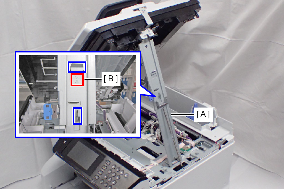
 Caution / 注意
Make sure that the support stand (A) is fixed with the two hooks, and the two triangle marks (B) face to each other.
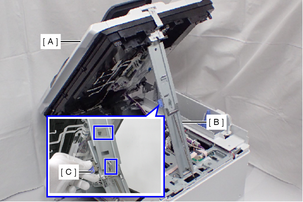
 Check Point / チェックポイント
When closing the ADF/SCN Unit (A), press the switch (C) on the ADF/SCN support stand (B) and hold up the ADF/SCN Unit to disengage the two hooks, then fold the ADF/SCN support stand.
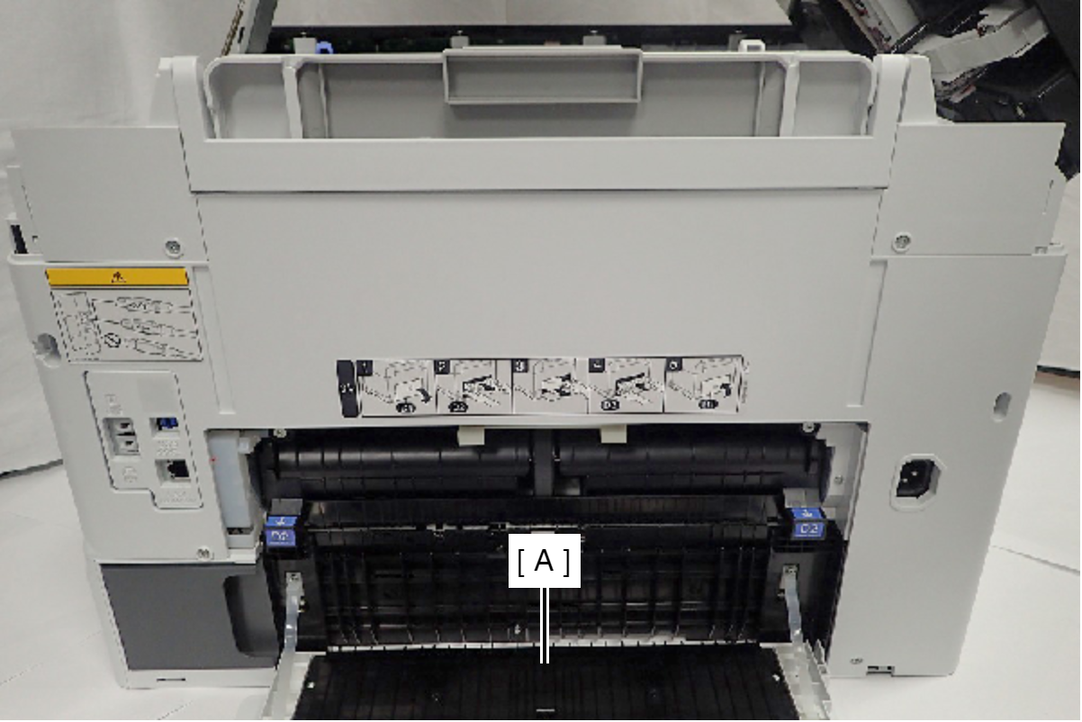
- Open the Duplex Print Cover (A).
- Remove the seven screws.
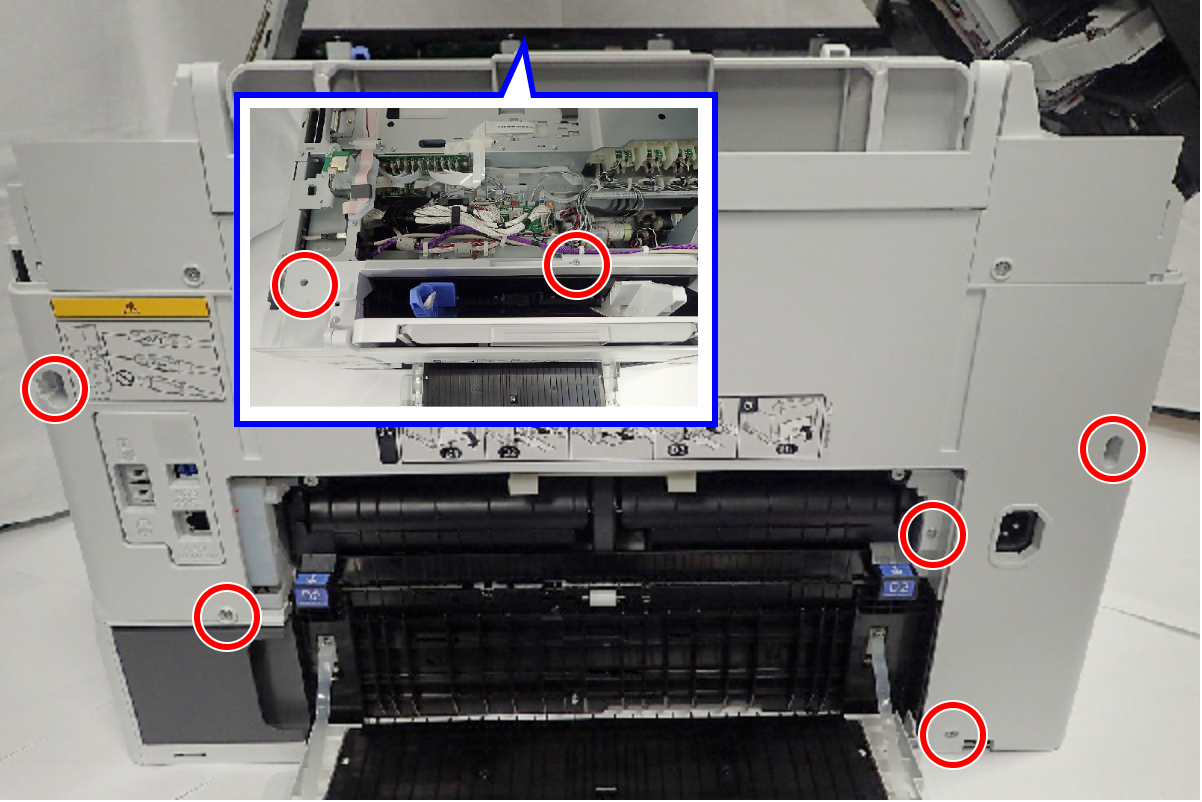
 : C.B.S-TITE-SCREW-3x8-F.ZN-3C
- Press the Rear Housing Assy (A) in the direction of the arrow, then release the hook.
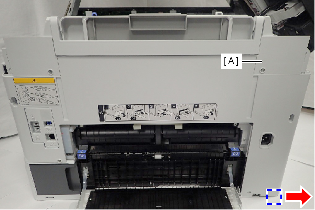
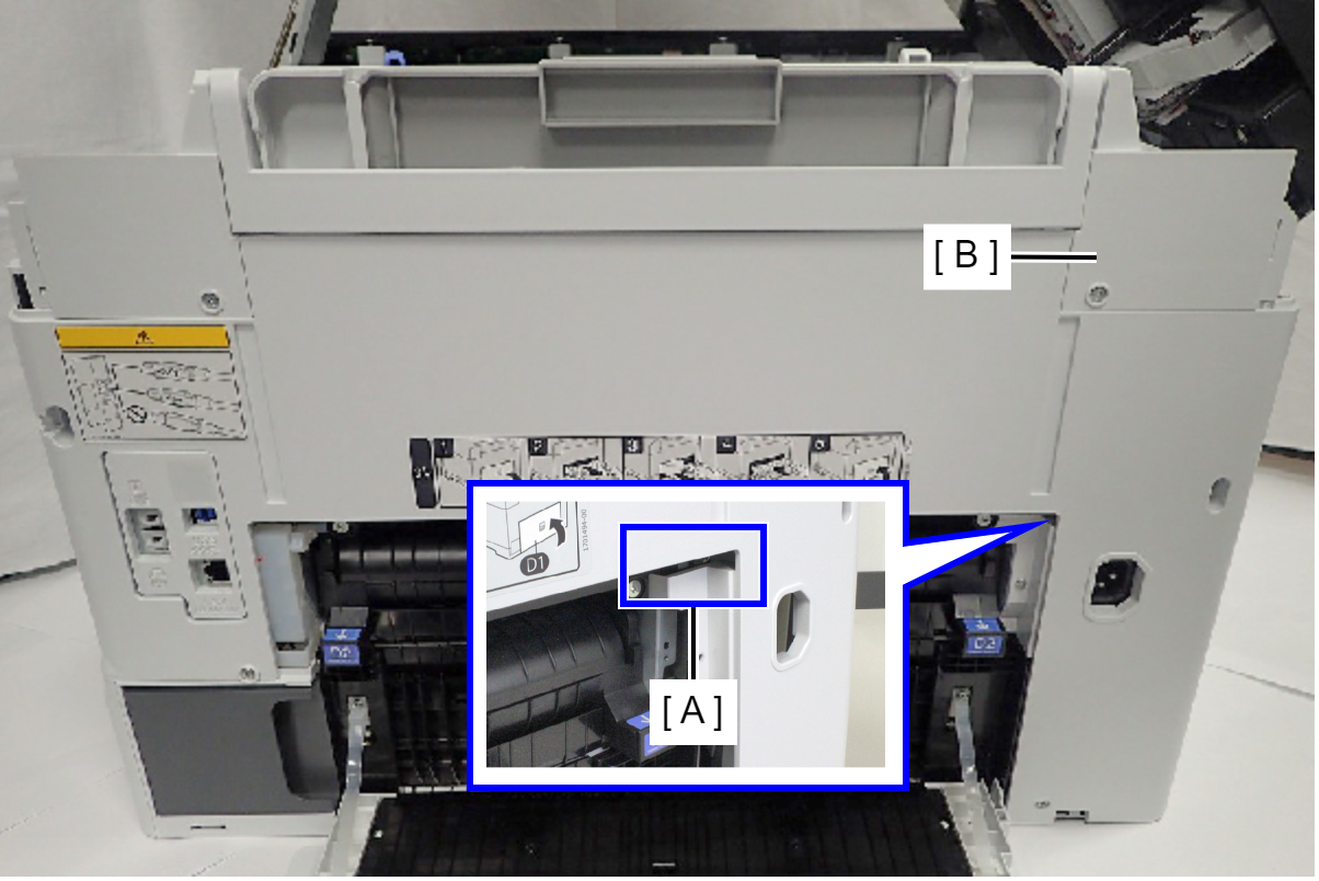
- Remove the Rear Housing Assy (B) while releasing the place interfering with the Rear ASF Unit (A).
- Release the Cable from two clamps (A).
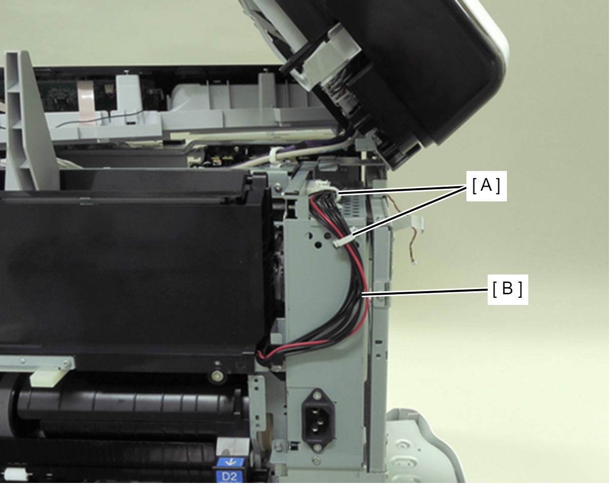
- Disconnect the cable (C) from connector (B) of Power Supply Unit (A).
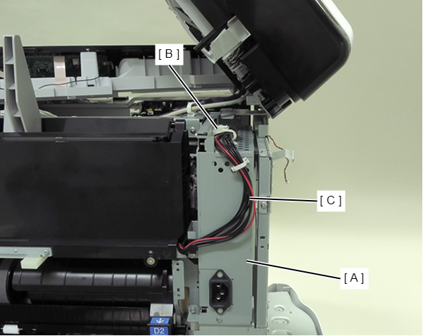
- Remove the four screws and then remove the Rear ASF Unit (A).
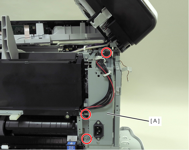
- : C.B.S-TITE-SCREW-3x8-F.ZN-3C
- Remove the four screws fastening the Left Housing (A).
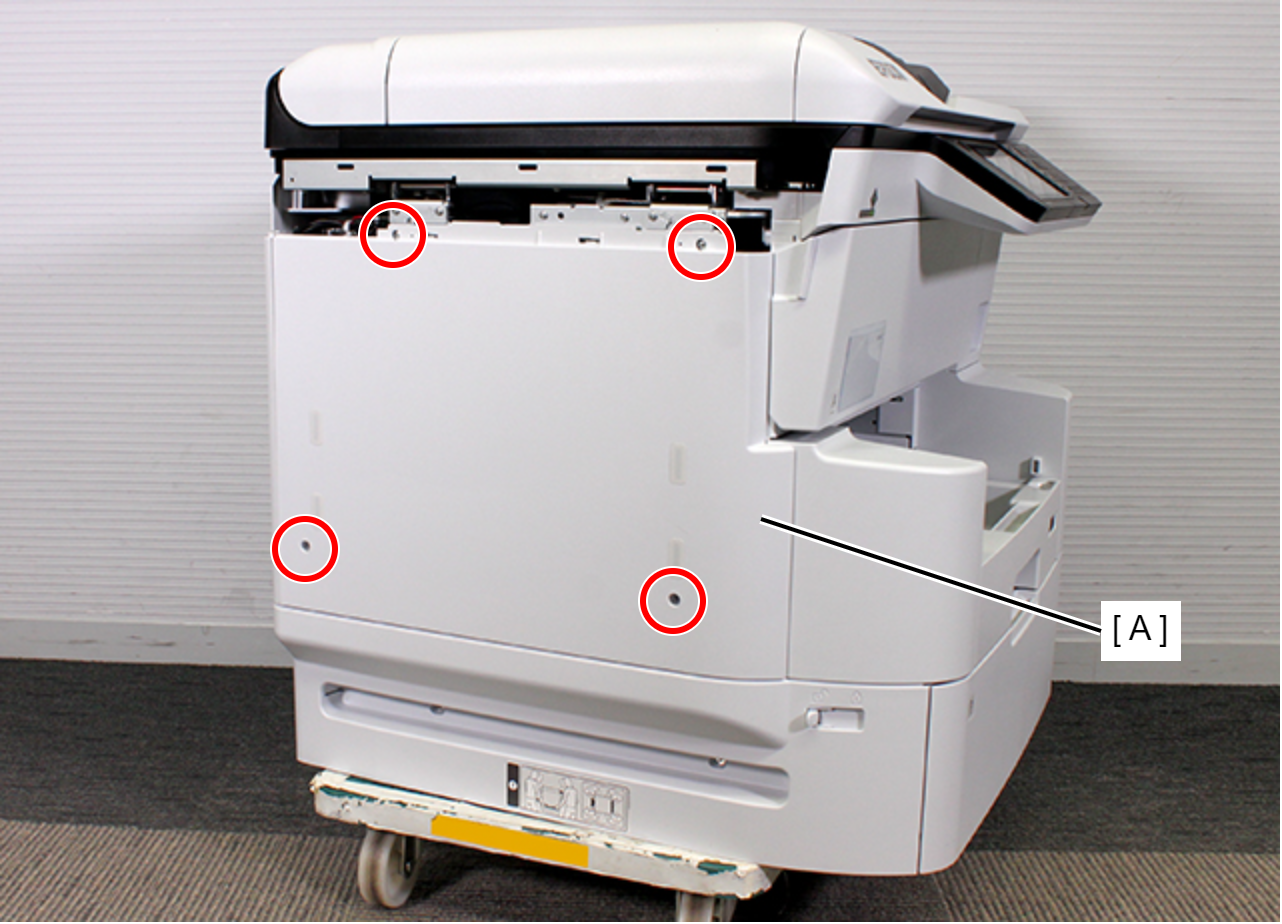
- : C.B.S-TITE-SCREW-3x8-F.ZN-3C
- Remove the two dowels.
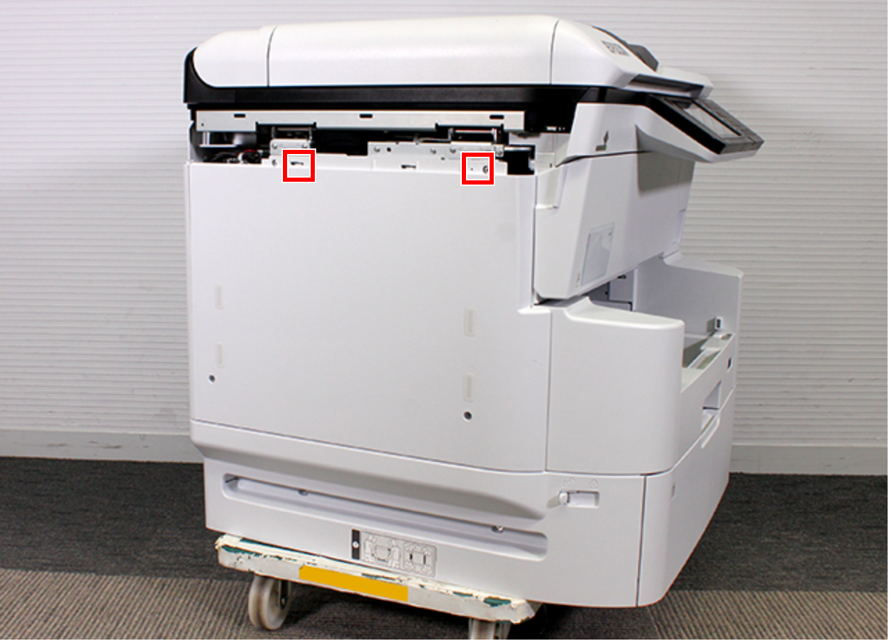
- Remove the rib on the front side while lifting up the Left Housing (A).
- Remove the rib on the back side while lifting up the Left Housing (A), release the hook (B) and then remove the Left Housing (A).
- Remove the six screws fastening the Power Supply Unit Mounting Plate (A).
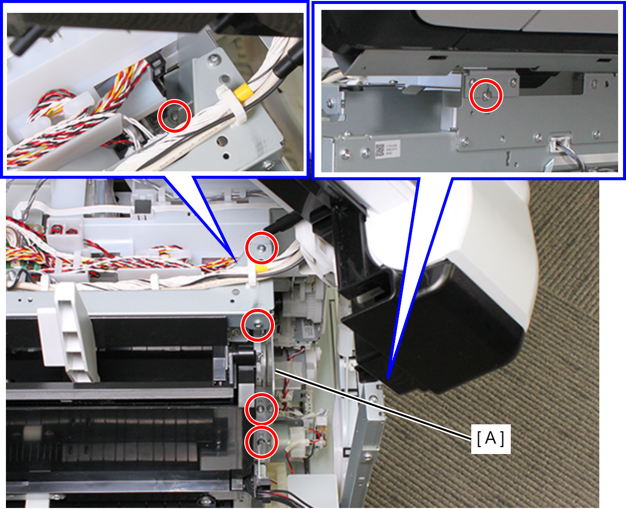
- : C.B.S-TITE-SCREW-3x8-F.ZN-3C
- Lift up the frame and remove a dowel (A).
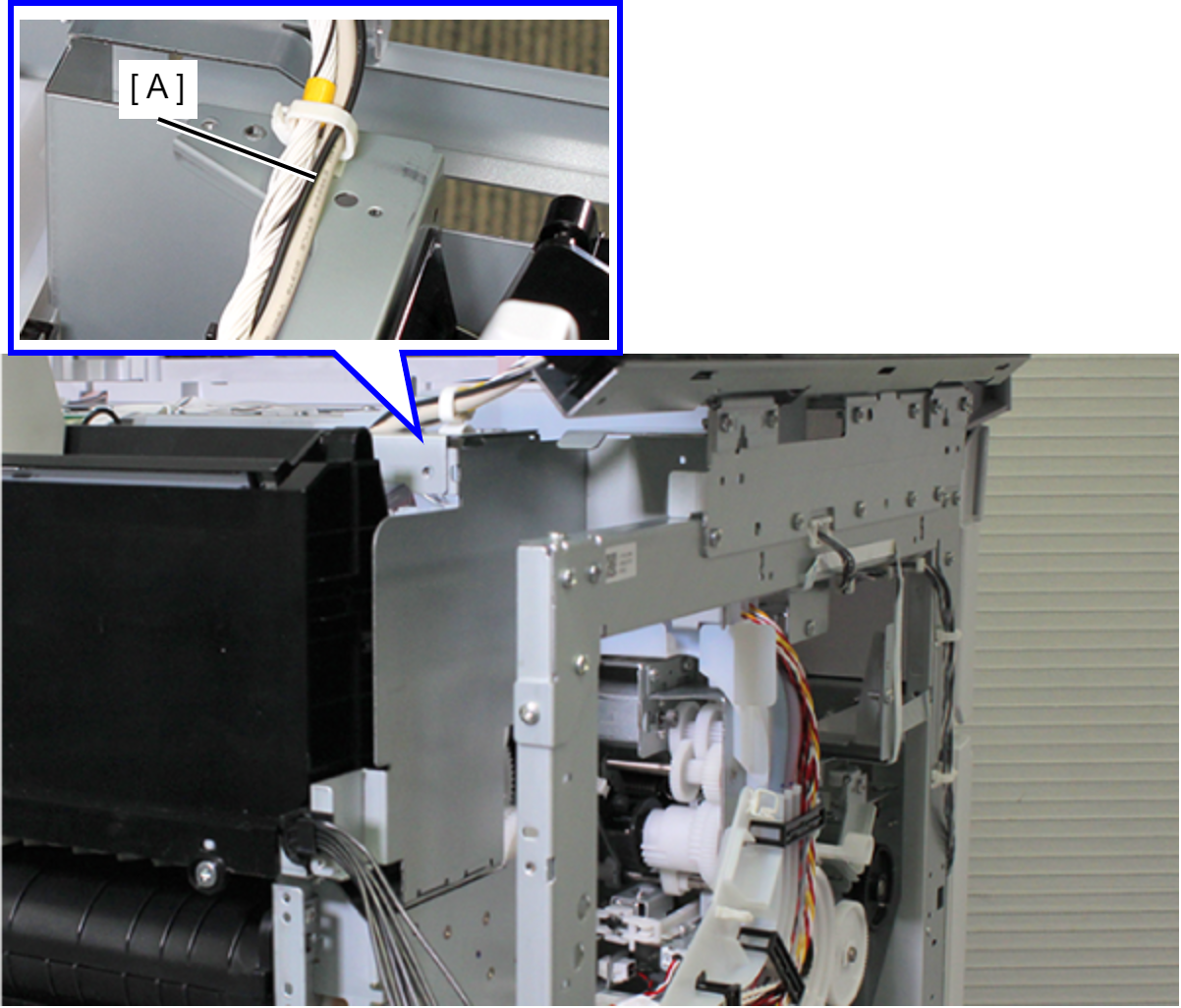
- Lift up the Power Supply Unit Mounting Plate (A), turn it in the direction of the arrow, and remove the two ribs (D) while releasing the unit interfering (C) with the Side Frame (B).
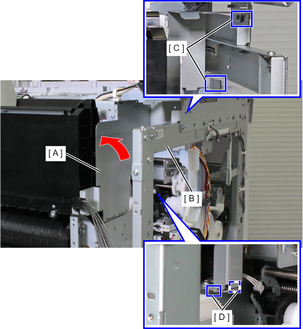
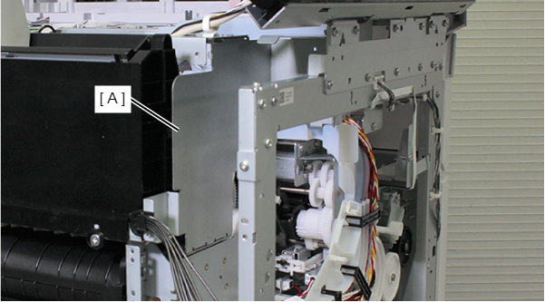
- Remove the Power Supply Unit Mounting Plate (A).
 Assembly / 組み立て
Before tightening the screws, make sure the positioning points are correctly assembled with reference to the figure below.
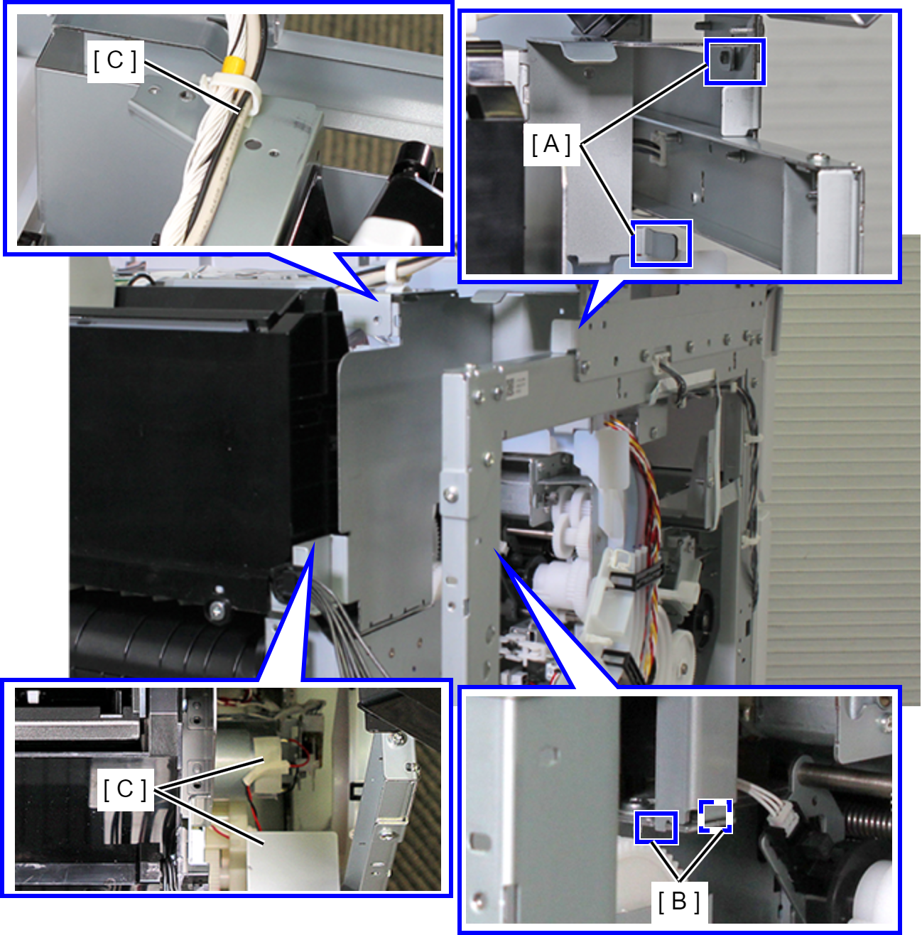
- A: Interfering Unit
- B: Rib
- C: Dowel
- Remove the screw fastening the Tube Guide (A).
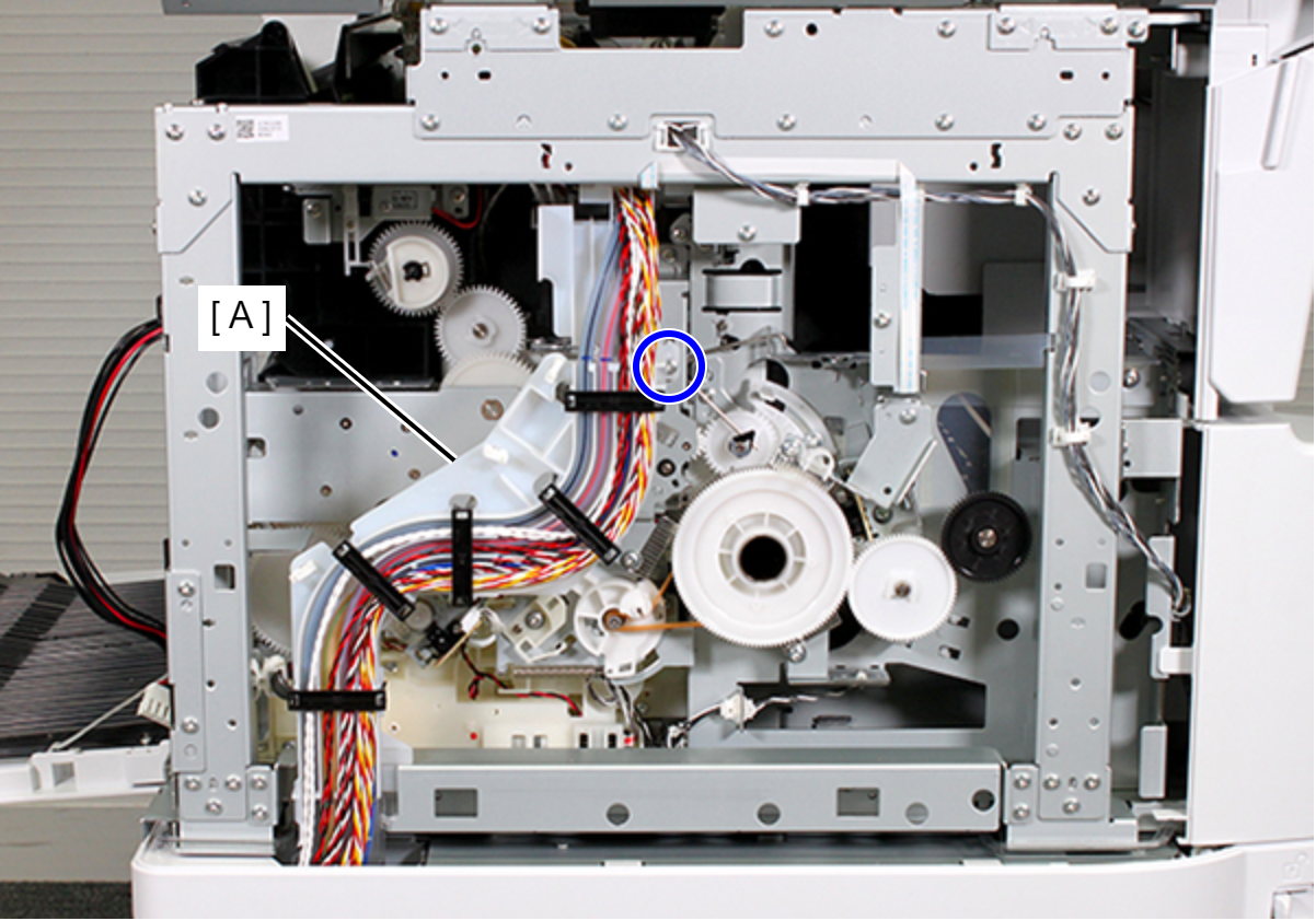
 : C.B.S-TITE-SCREW-3x8-F.ZN-3C
- Remove the interfering unit, and retract the Tube Guide (A) to the back side.
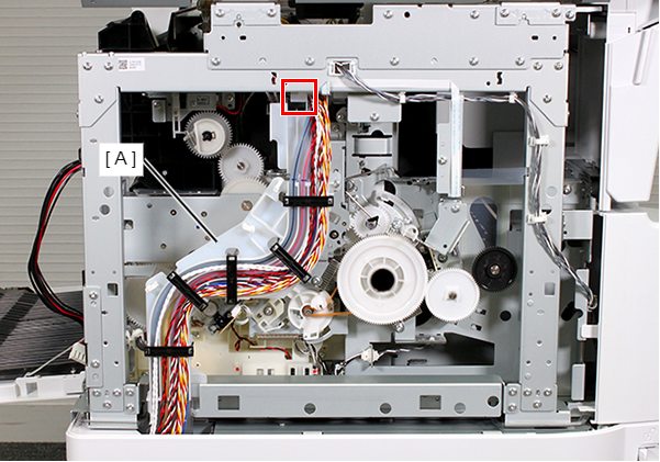
- Remove the screw, then remove the PF Brush Assy (A).
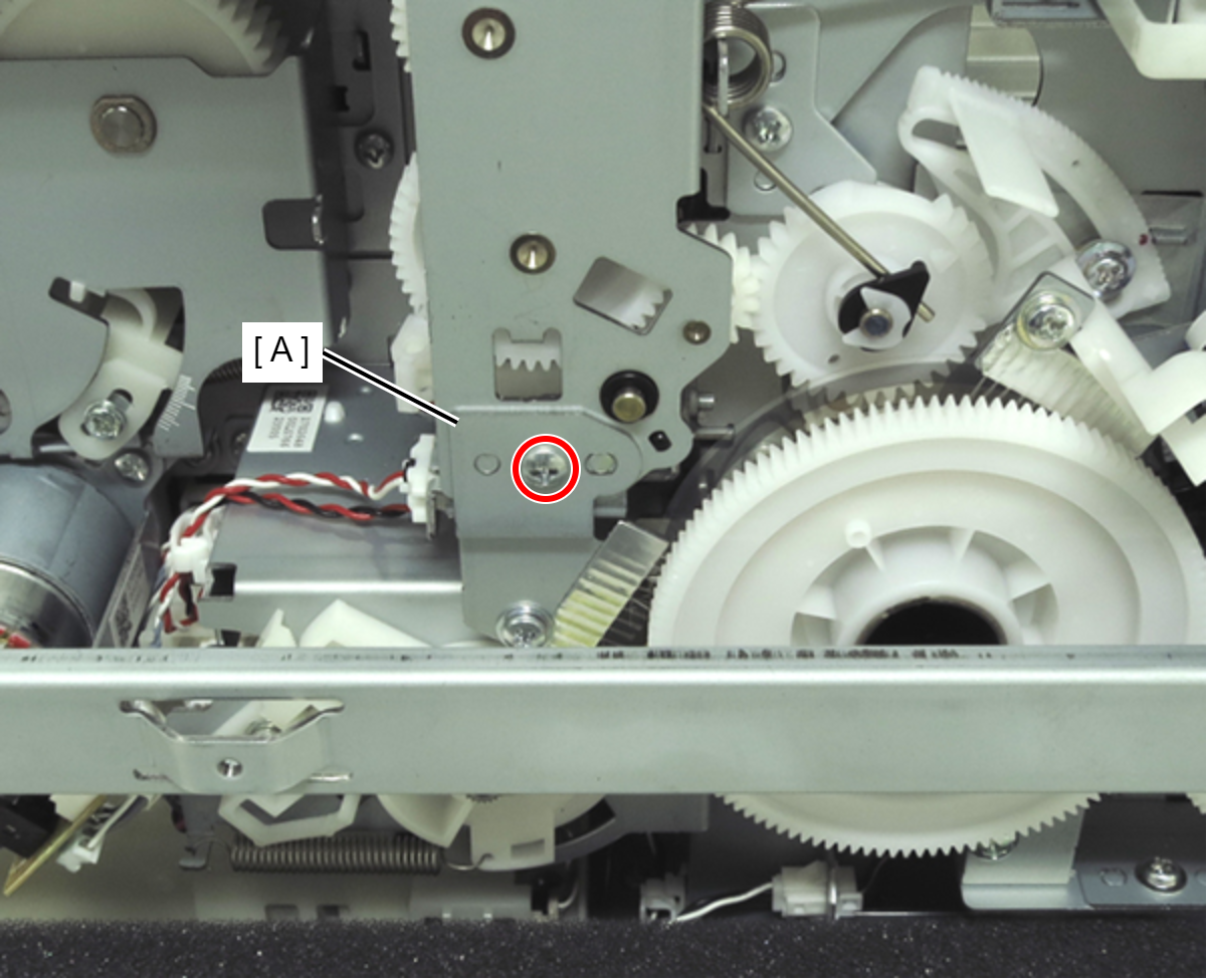
- :C.B.S-TITE-SCREW-3x6-F.ZN-3C
- Remove the two screws, then remove the APG Drive Assy (A).
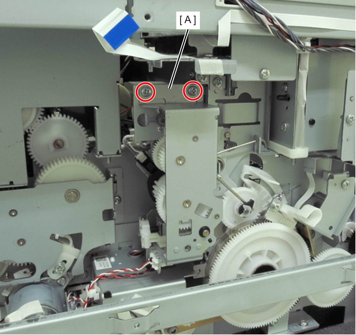
- : C.B.S-TITE-SCREW-3x6-F.ZN-3C
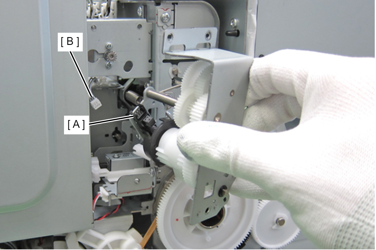
- Disconnect the cable (B) from the connector (A) of the sensor.
 Assembly / 組み立て
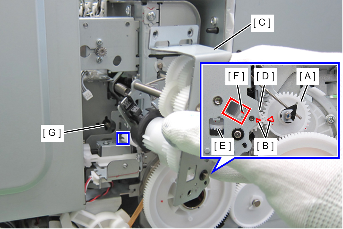
- Align the triangle mark (B) on the left APG cam (A) with the triangle mark (B) on the spur gear 14.4 (D) on the APG Drive Assy (C). At this point, make sure the mark (F) on the combination gear (E) can be seen through the hole on the APG Drive Assy (C).
- Insert the pin (G) on the upper paper guide into the groove on the release shaft holder of the APG Drive Assy.
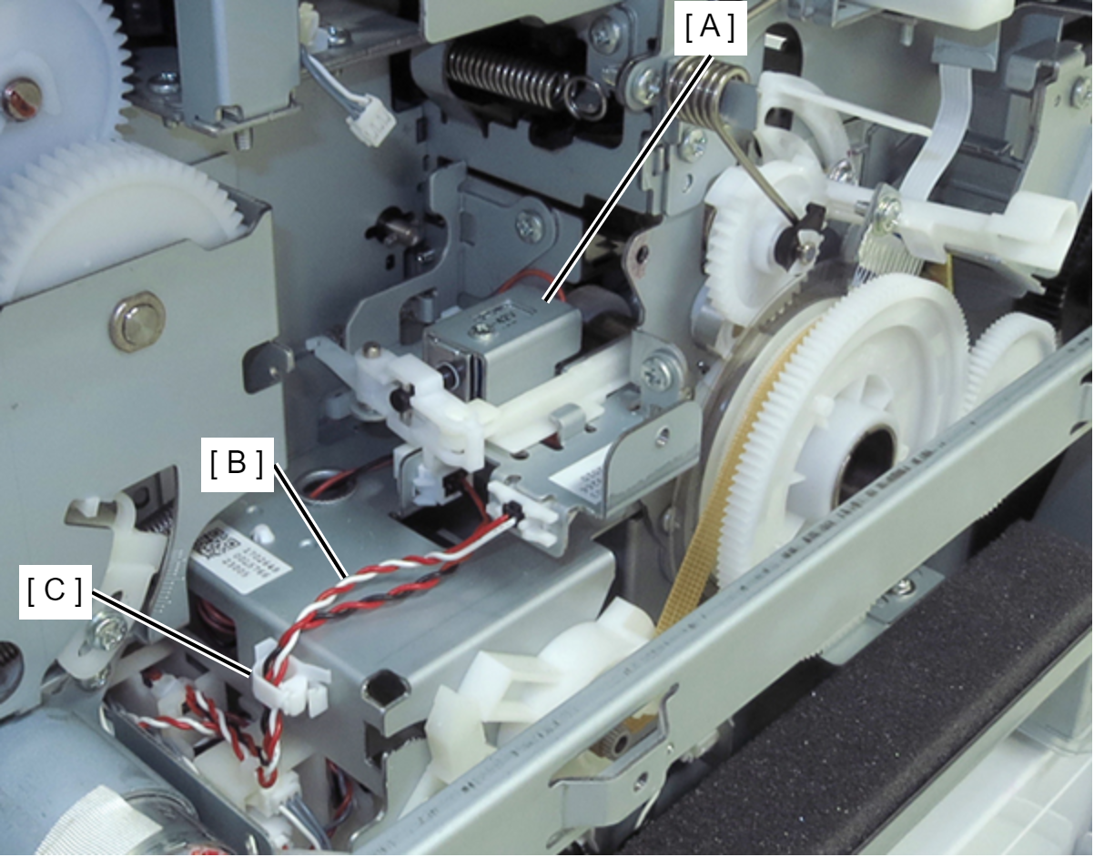
- Release the cable (B) of the PW Drive Shutter (A) from the clamp (C).
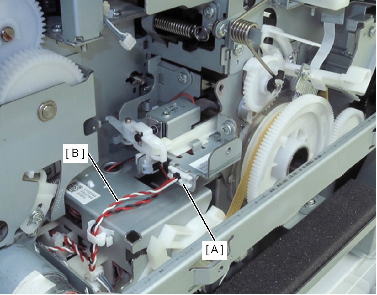
- Disconnect the cable (B) from the relay connector (A).
- Remove the two screws, then remove the PW Drive Shutter (A).
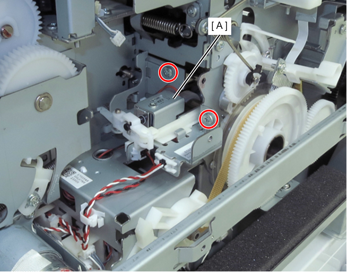
- : C.B.S-TITE-SCREW-3x6-F.ZN-3C
- Remove the E-ring (A) and remove the spur gear 56.8 (B).
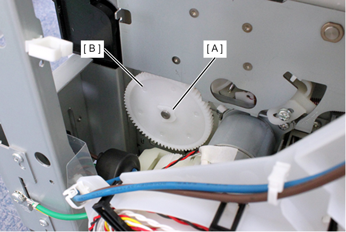
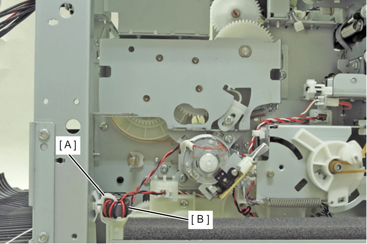
- Release the ferrite core (B) from the clamp (A).
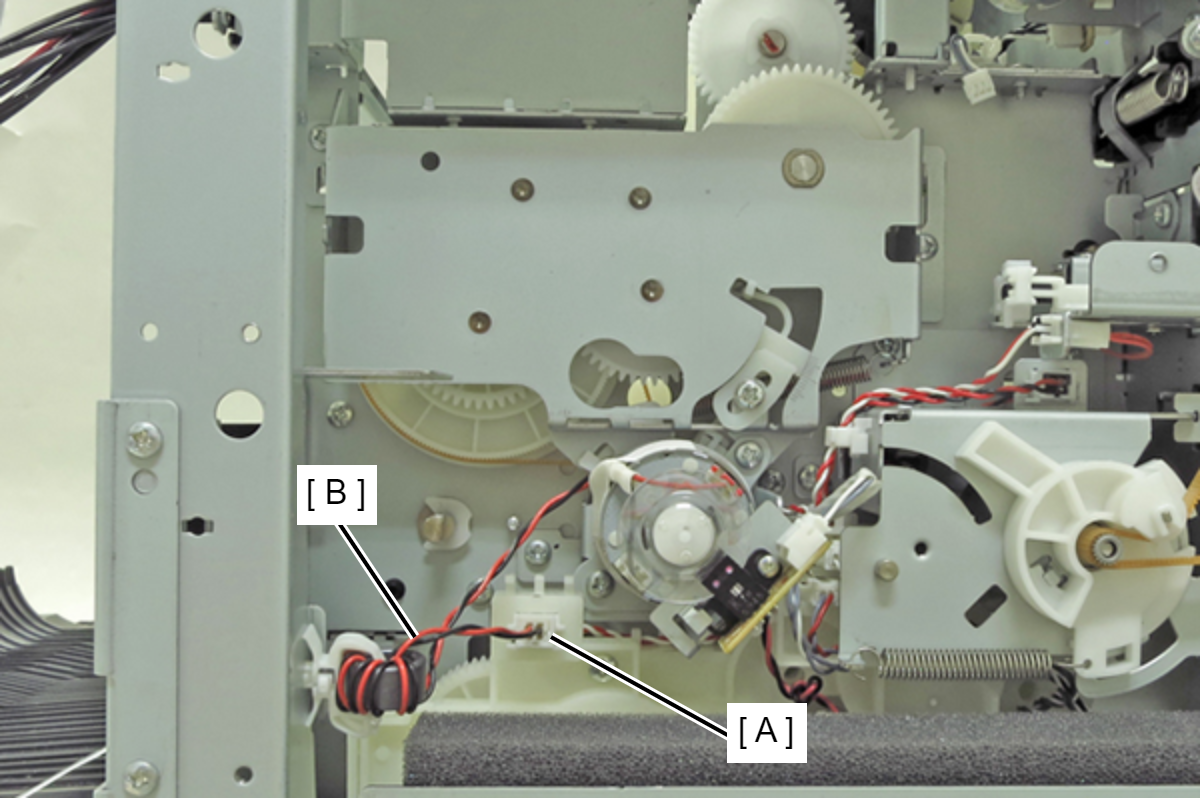
- Disconnect the motor cable (B) from the relay connector (A).
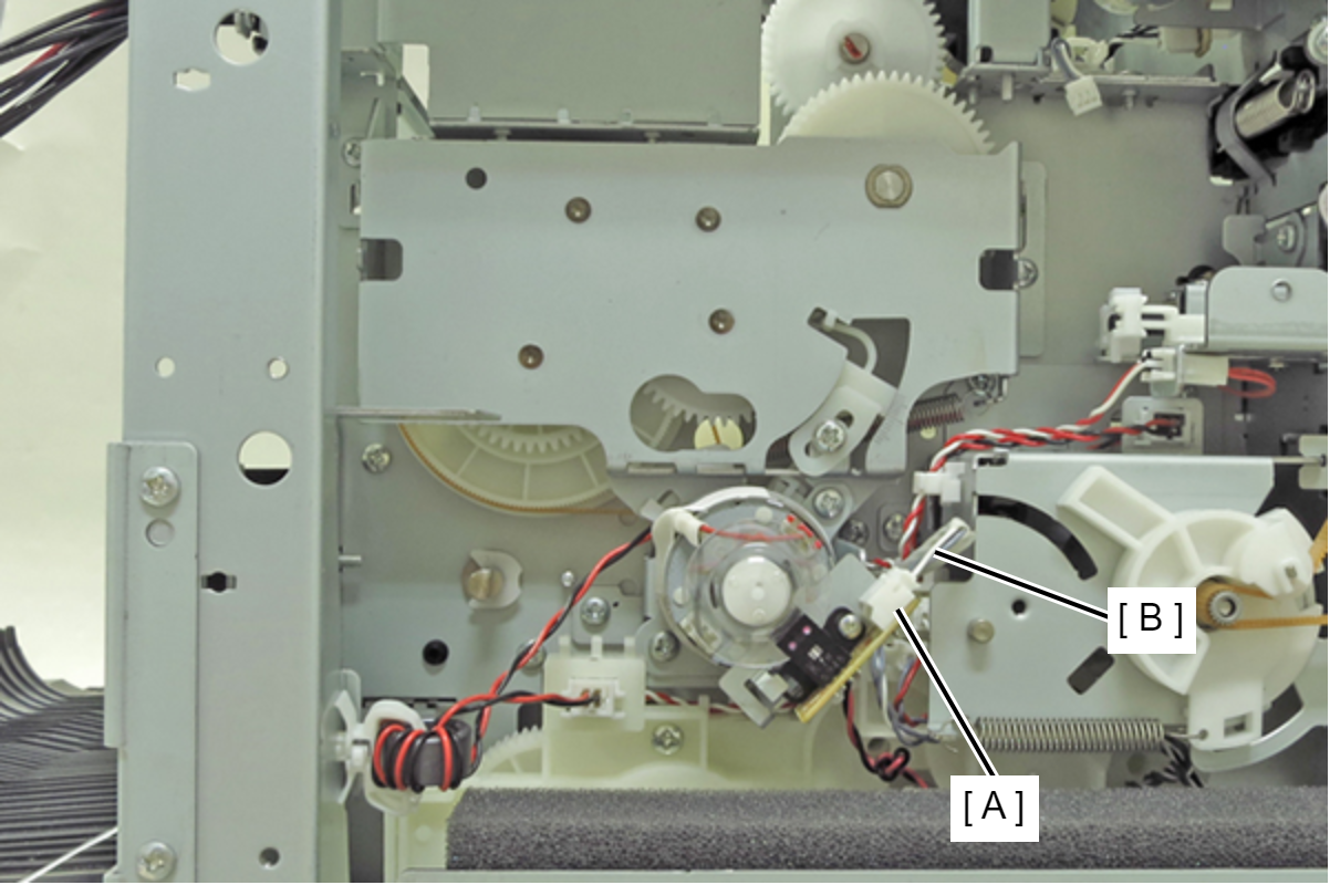
- Disconnect the sensor cable (B) from the connector (A).
- Remove the four screws, then remove the ASF Drive Assy (A).
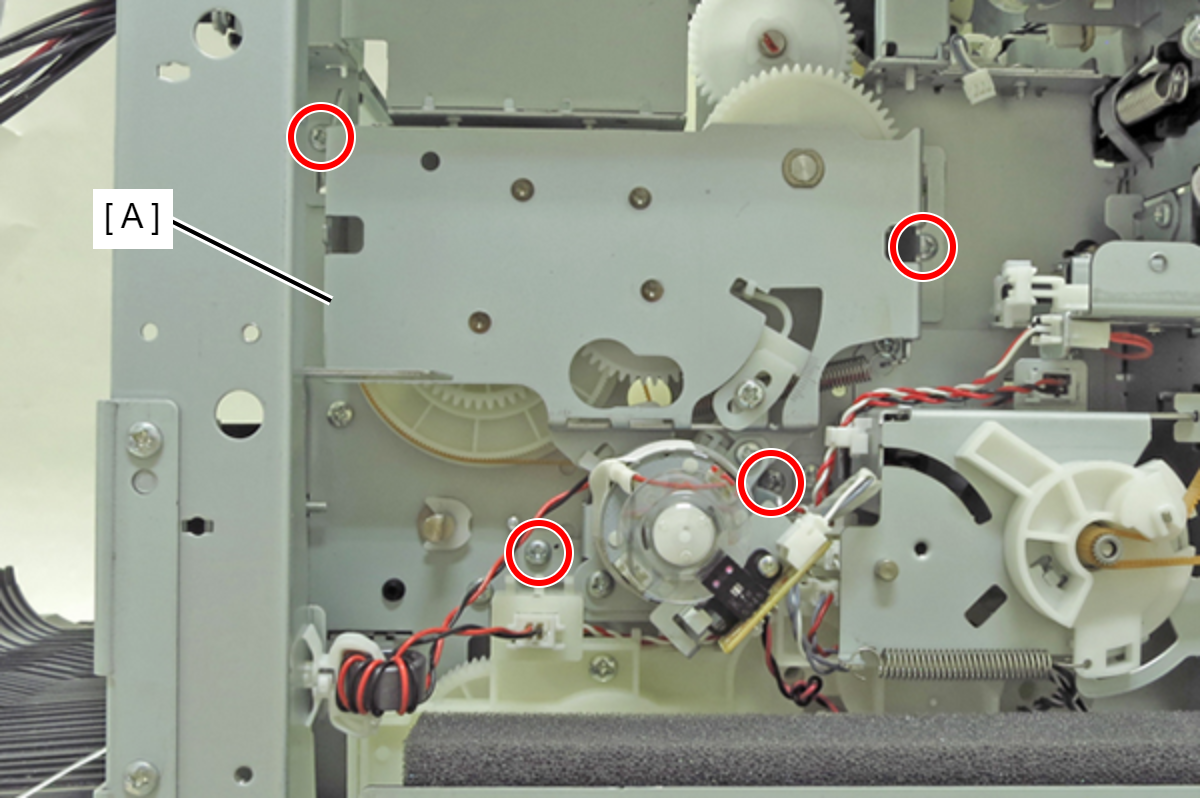
- : C.B.S-TITE-R-SCREW-3x6-F.ZN-3C
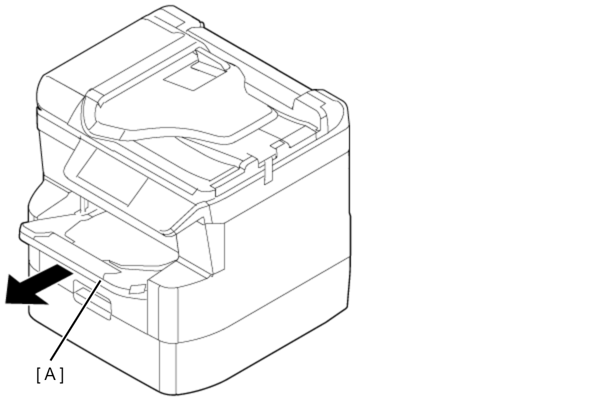
- Remove the Stacker Assy (A).
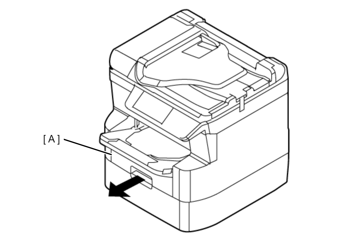
- Remove the Cassette Assy (A).
- Remove the screw.
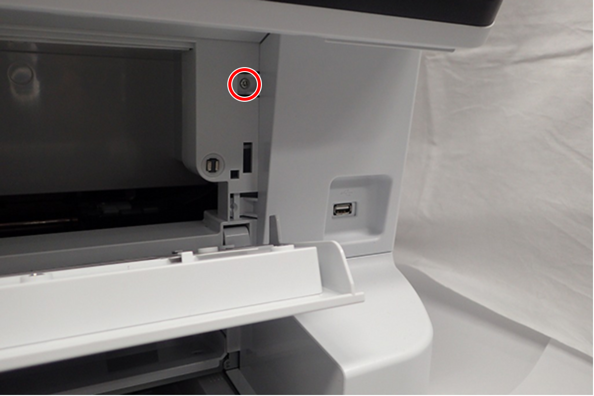
- : C.B.S-TITE-SCREW-3x8-F.ZN-3C
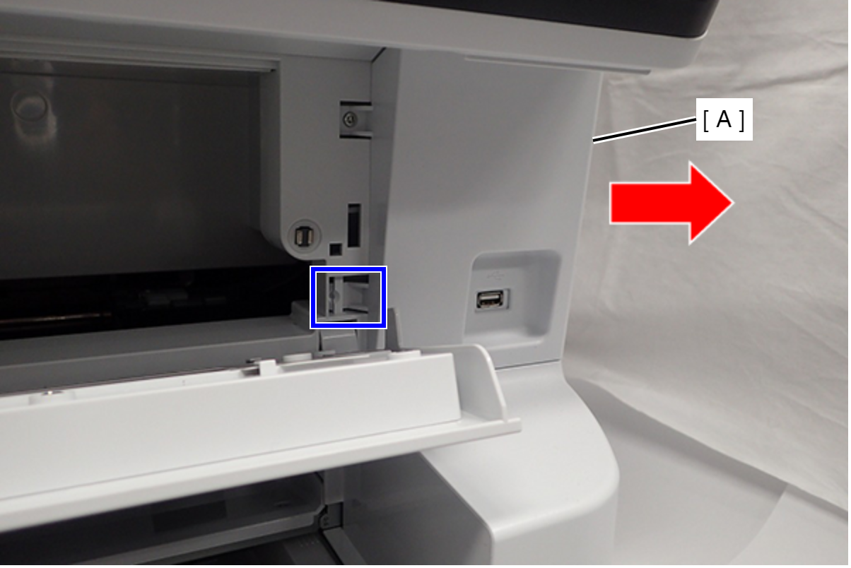
- Release the Hook, then slide the Front Right Cover (A) to direction of arrows and remove it.
- Remove the five screws. (one of them is also securing the panel ground wire)
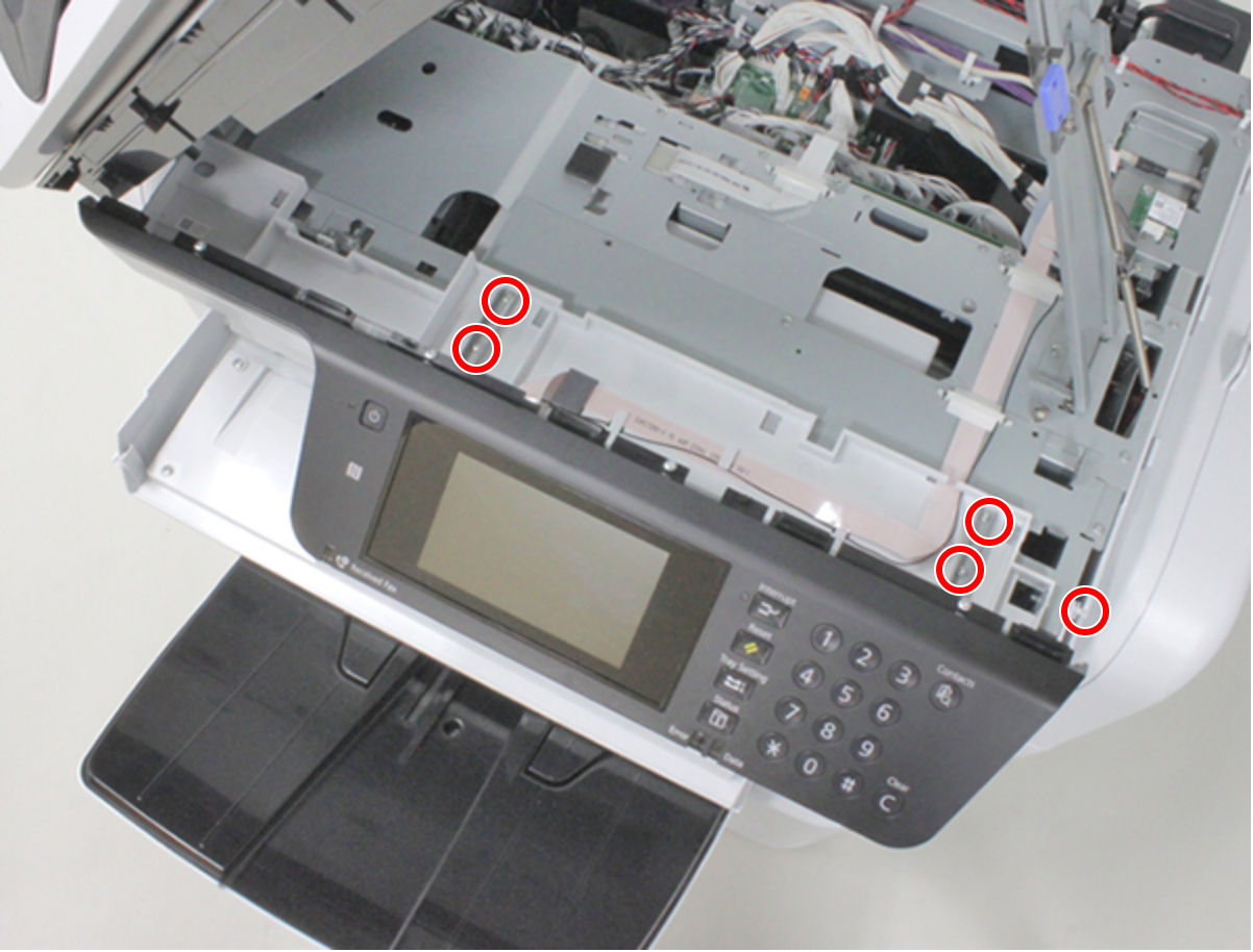
- : C.B.S-TITE-SCREW-3x8-F.ZN-3C
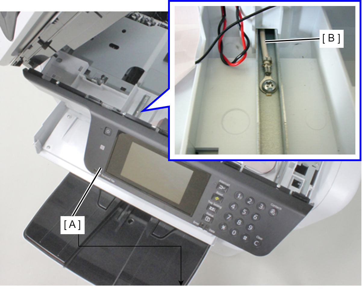
Assembly / 組み立てThere is a place to fasten the grounding wire (B) together when fixing the panel (A).
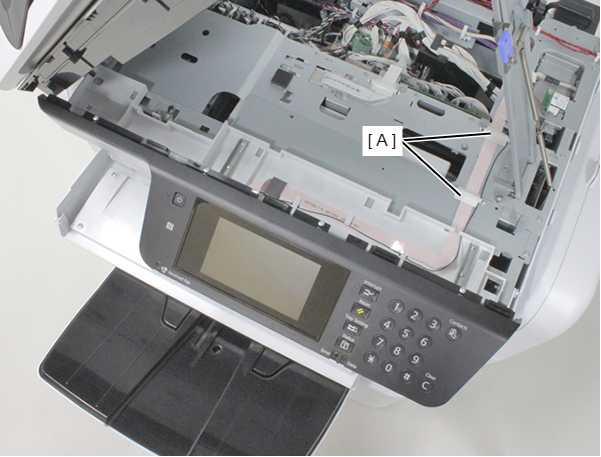
- Remove the two FFC clamps (A).
- Release the Panel FFC (A) and the grounding wire (B) from the guide (C).
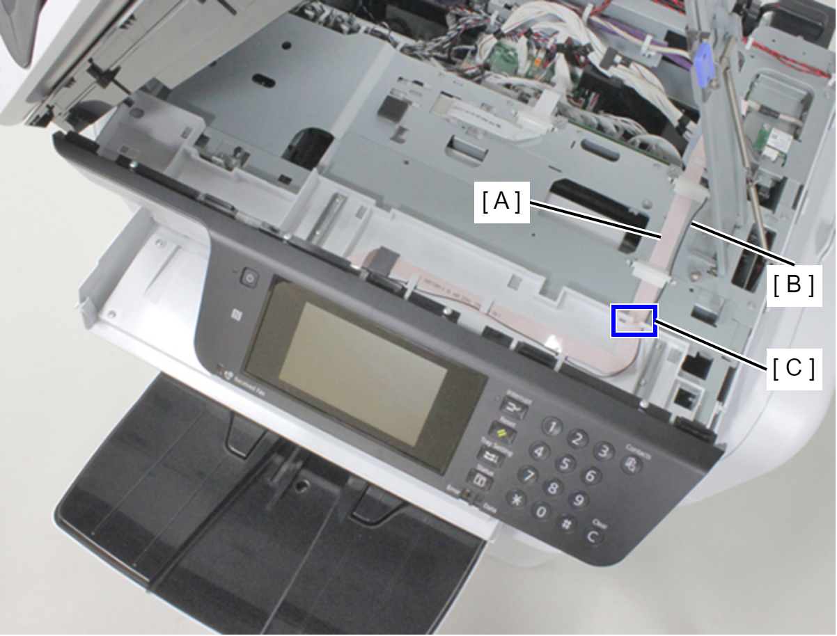
- Open the Front Cover Assy (A).
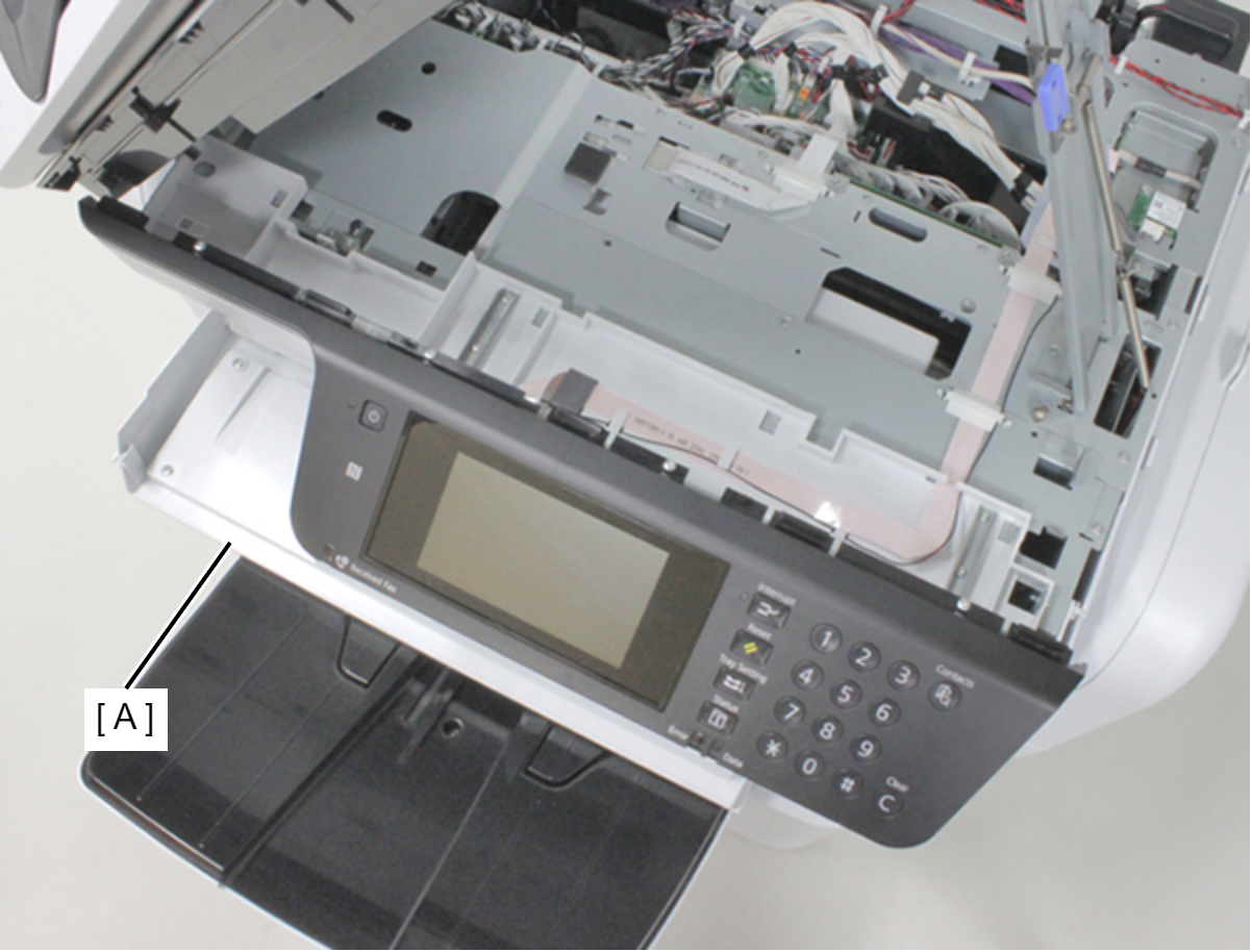
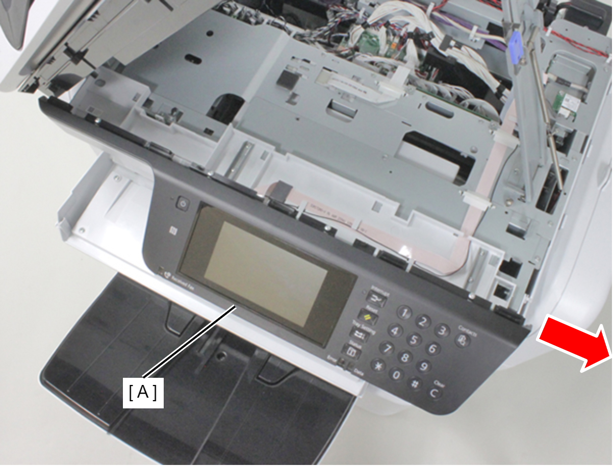
- Slide the panel unit (A) rightward to remove it.
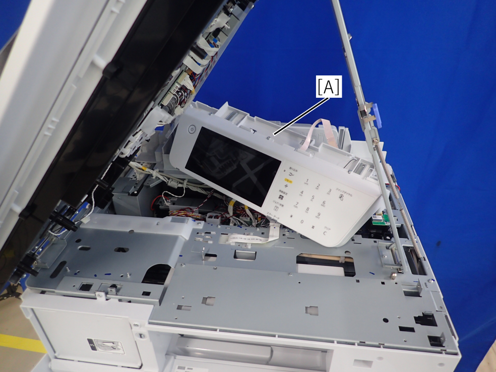
- Put the Panel Unit (A) at the rear side of the printer.
- Remove the seven screws, then remove the Front Housing Frame Assy (A).
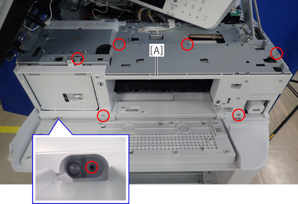
- : C.B.S-TITE-R-SCREW-3x6-F.ZN-3C
- Remove the two screws, then remove the Front Left Housing (A).
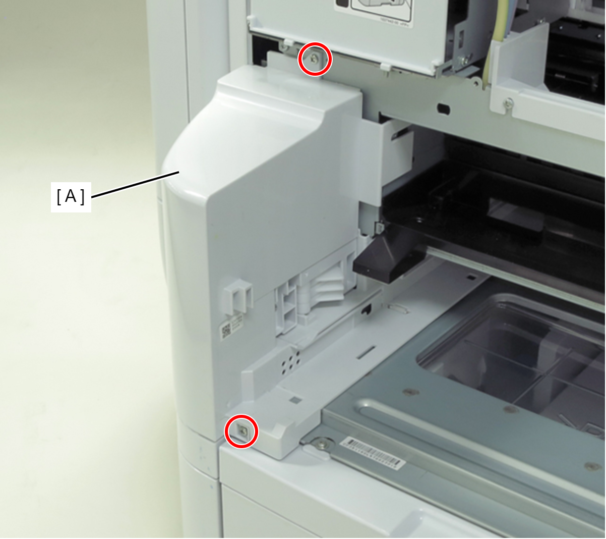
- : C.B.S-TITE-SCREW-3x8-F.ZN-3C
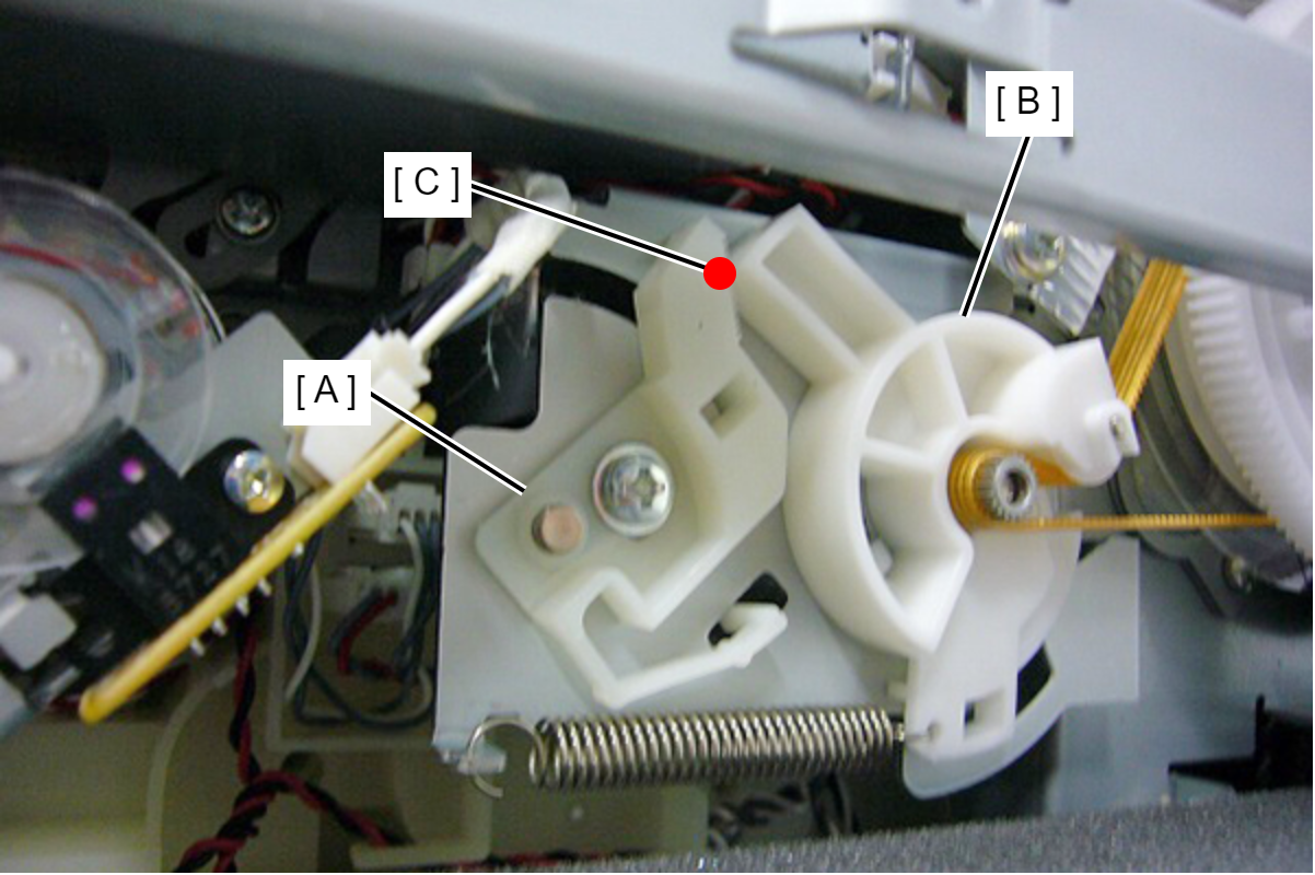
- The PF Belt Tension Stopper (A) is in contact with the PF Drive Pulley Holder (B). Put a mark (C) on the contact point.
- Loosen the screw that secures the PF Belt Tension Stopper (A).
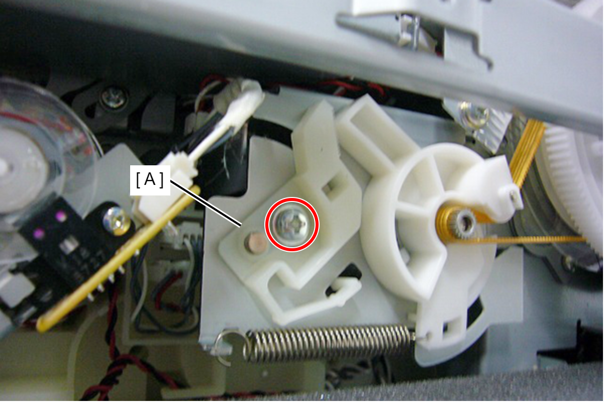
- : C.B.S-TITE.P4.SCREW-3x8-F.ZN-3C
- Release the leg (B) of the PF Belt Tension Stopper (A) from the frame, then slide the PF Belt Tension Stopper rearward to remove it.
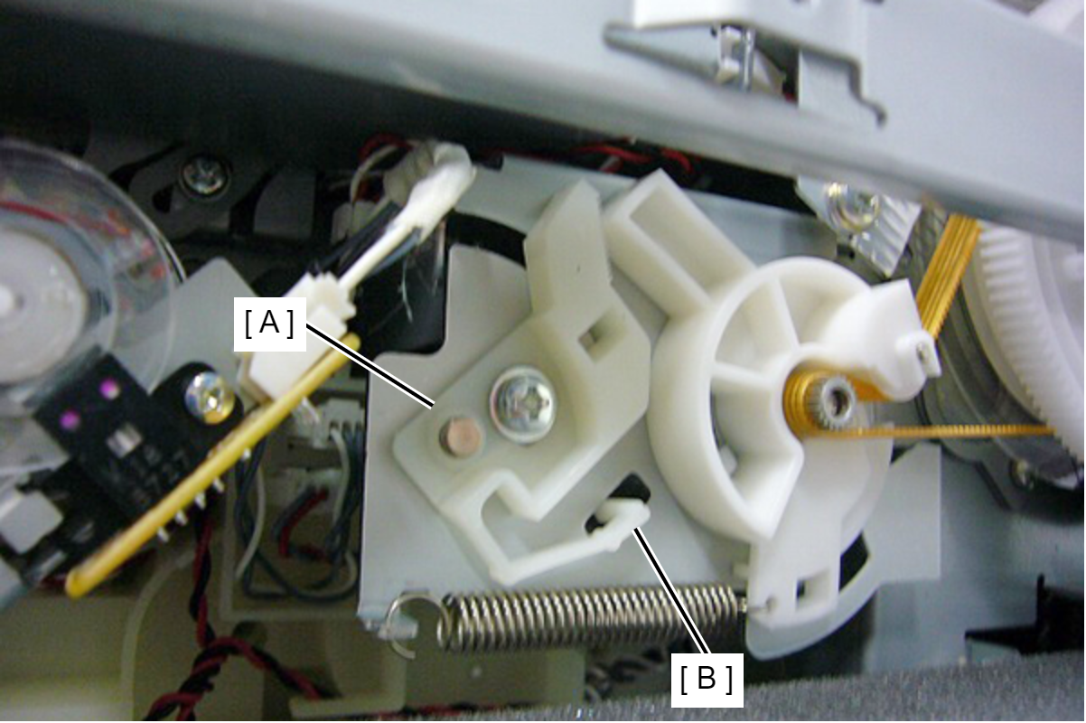
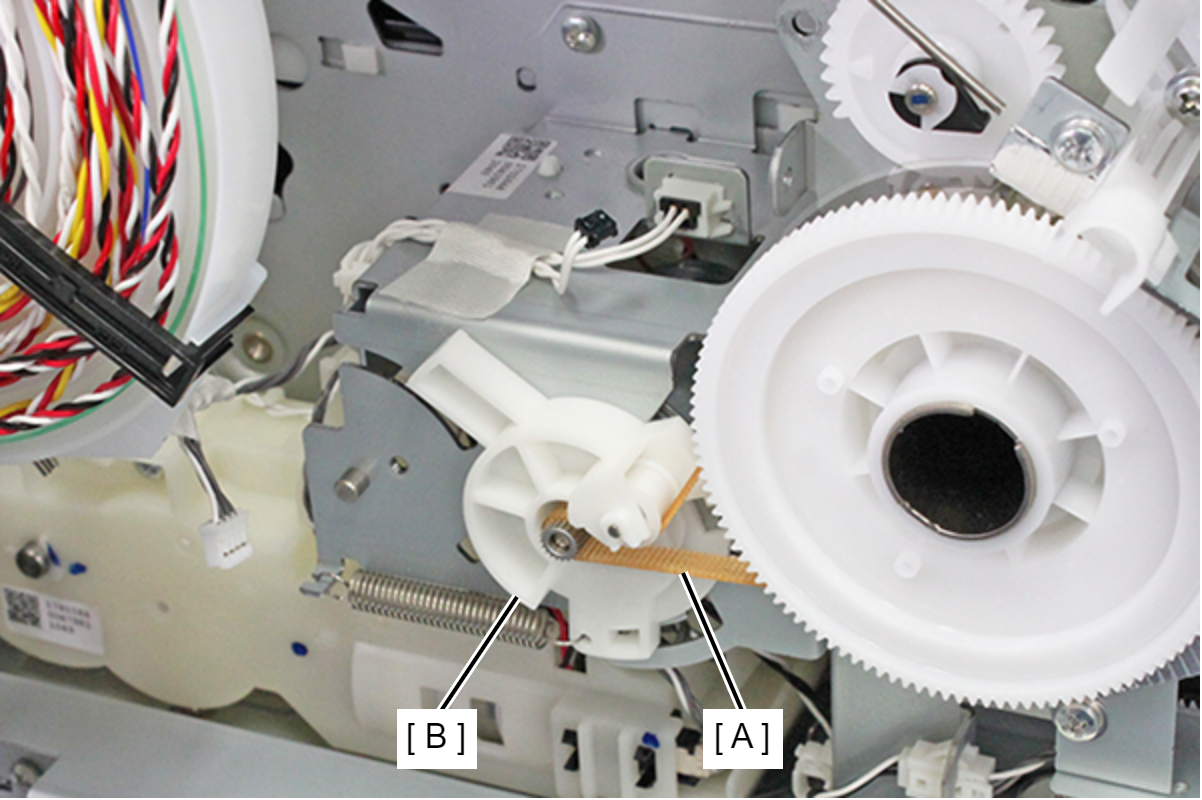
- Remove the PF Timing Belt (A) from the PF Drive Pulley Holder (B).
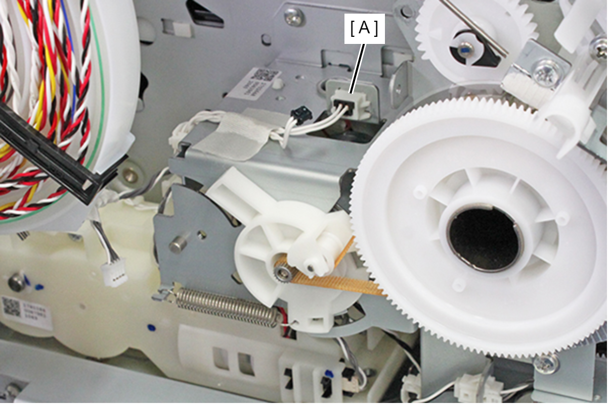
- Remove the cable from the relay connector (A).
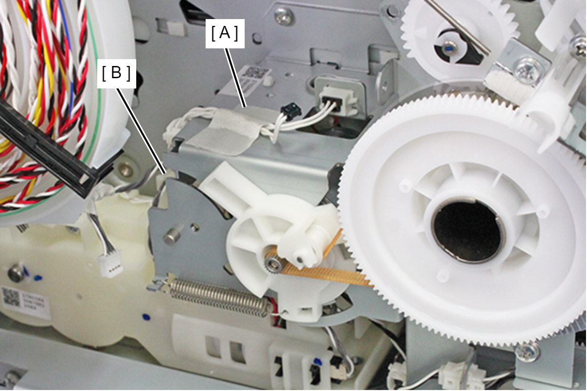
- Peel away the acetate tape (A) and release the two cables from the clamp (B).
- Remove the four screws, then remove the PF Drive Assy (A).
- : C.B.S-TITE-R-SCREW-3x6-F.ZN-3C
- Open the Duplex Print Cover (A).
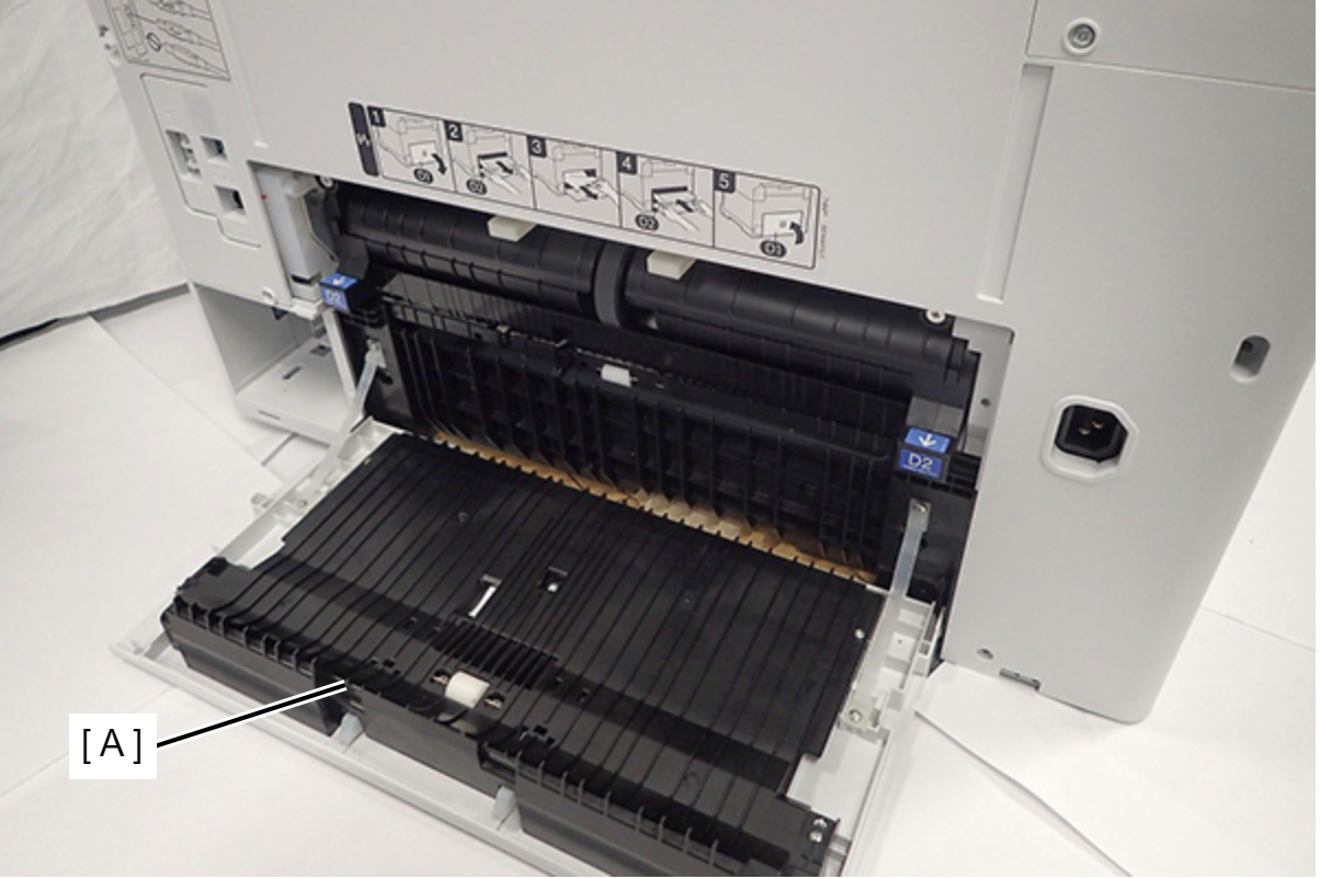
- Remove the Duplex Print Assy (A).
- Remove the two screws.
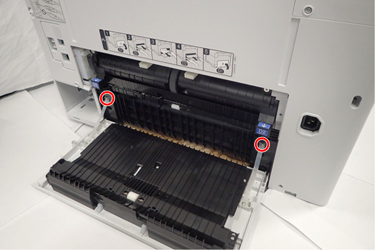
- : C.B.P-TITE-SCREW-3x10-F.ZN-3C
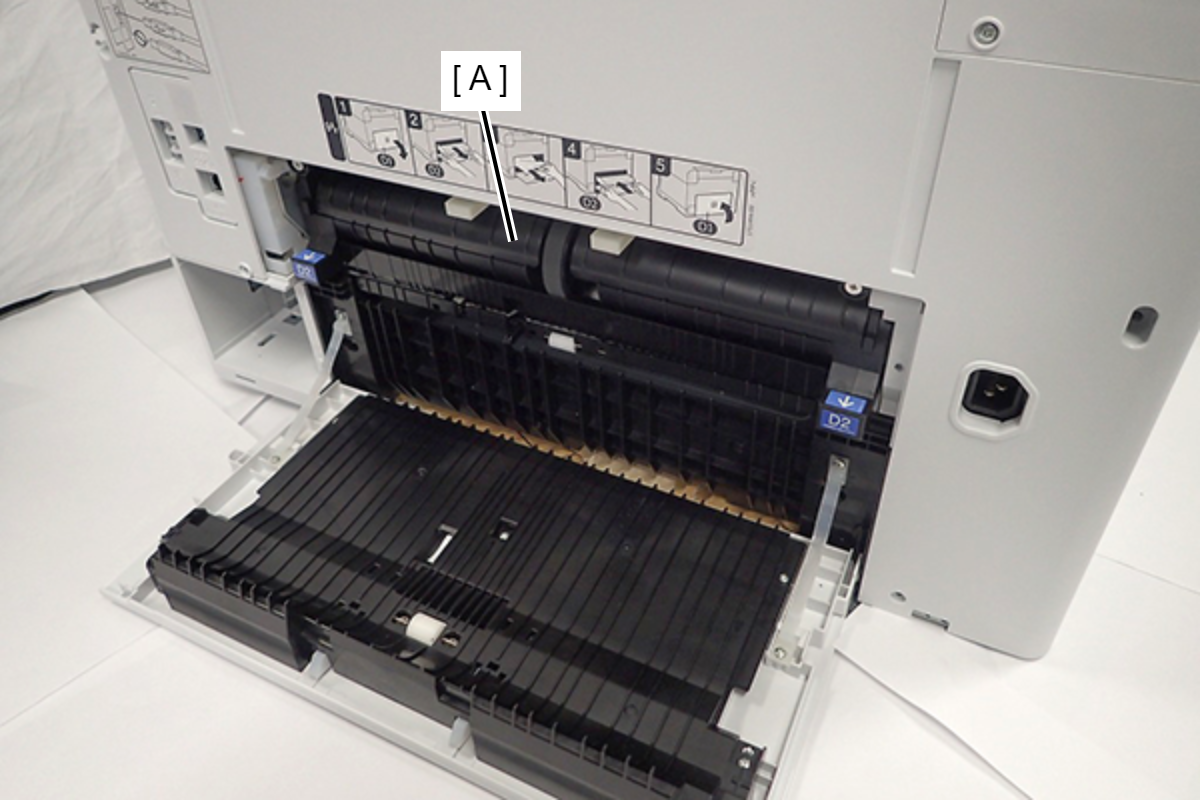
- Disengage the two dowels, then remove the Duplex Print Cover Assy (A).
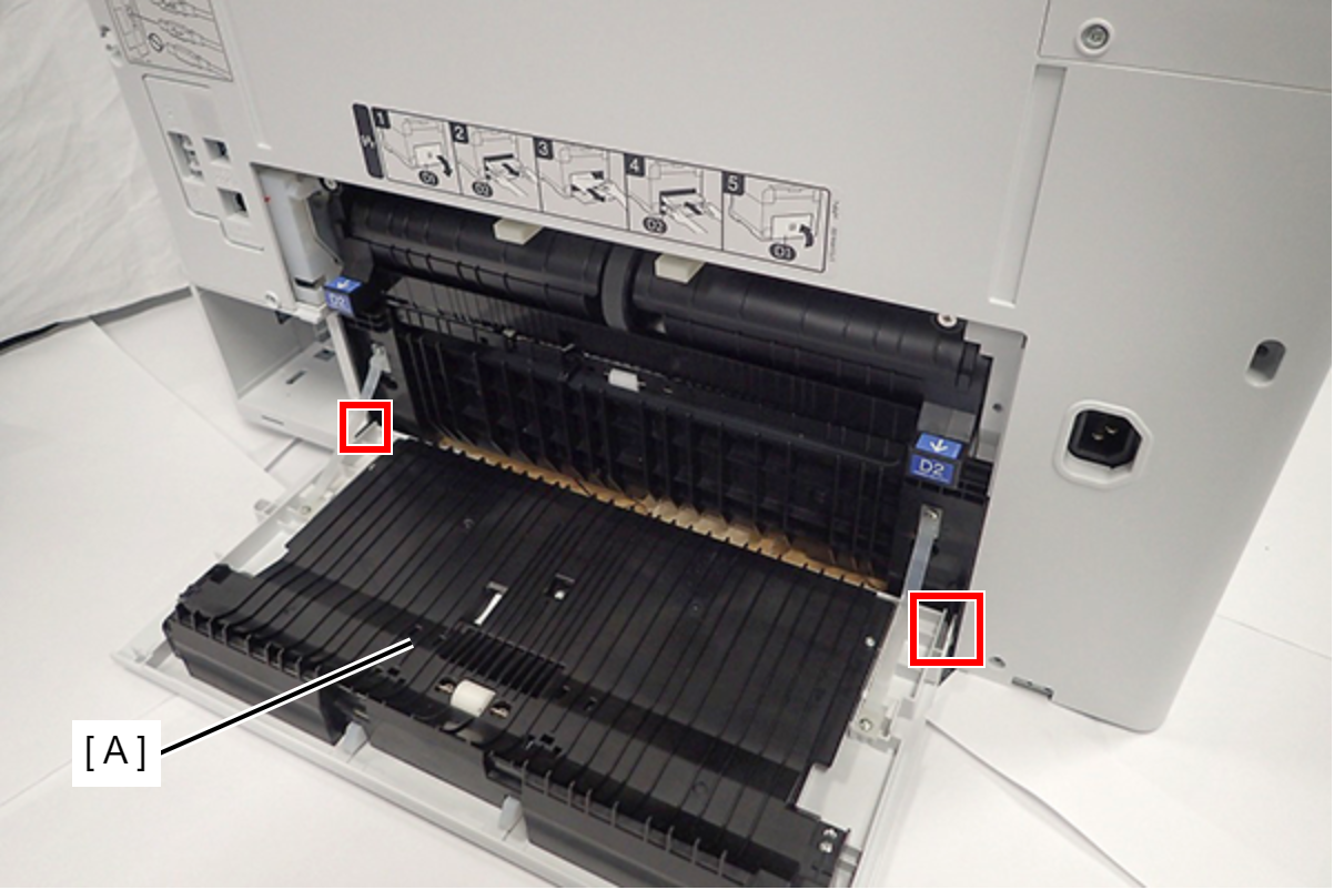
- Remove the two screws, then remove the Middle Inner Housing (A).
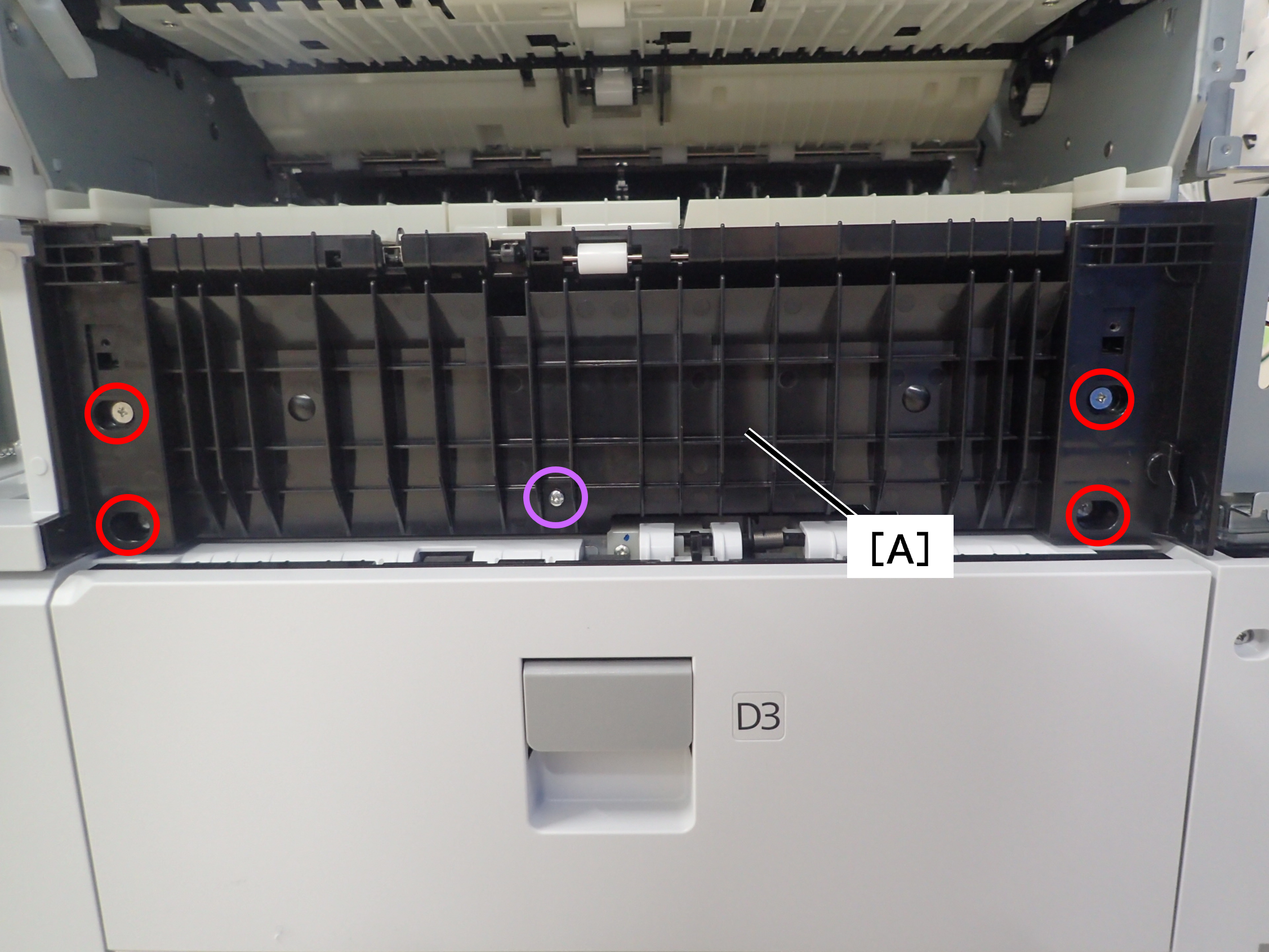 C.SHOULDER S-TITE,3x4
 C.B.P-TITE-SCREW-2.5x10-F.ZN-3C
 - Remove the four screws, then remove the Frame (A).
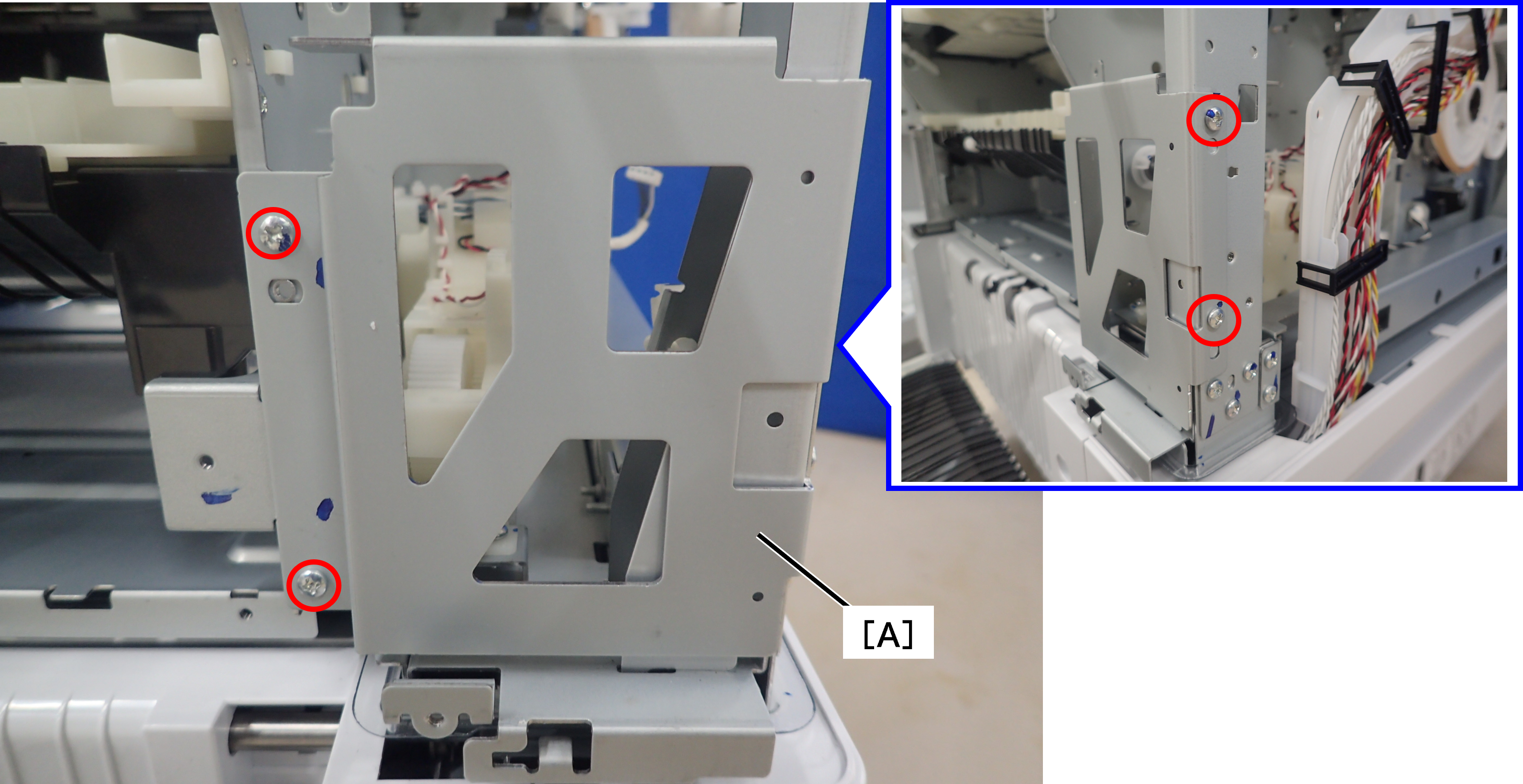 C.B.S-TITE-SCREW-3x8-F.ZN-3C
 - Remove the E-ring (A) and remove the spur gear (B).
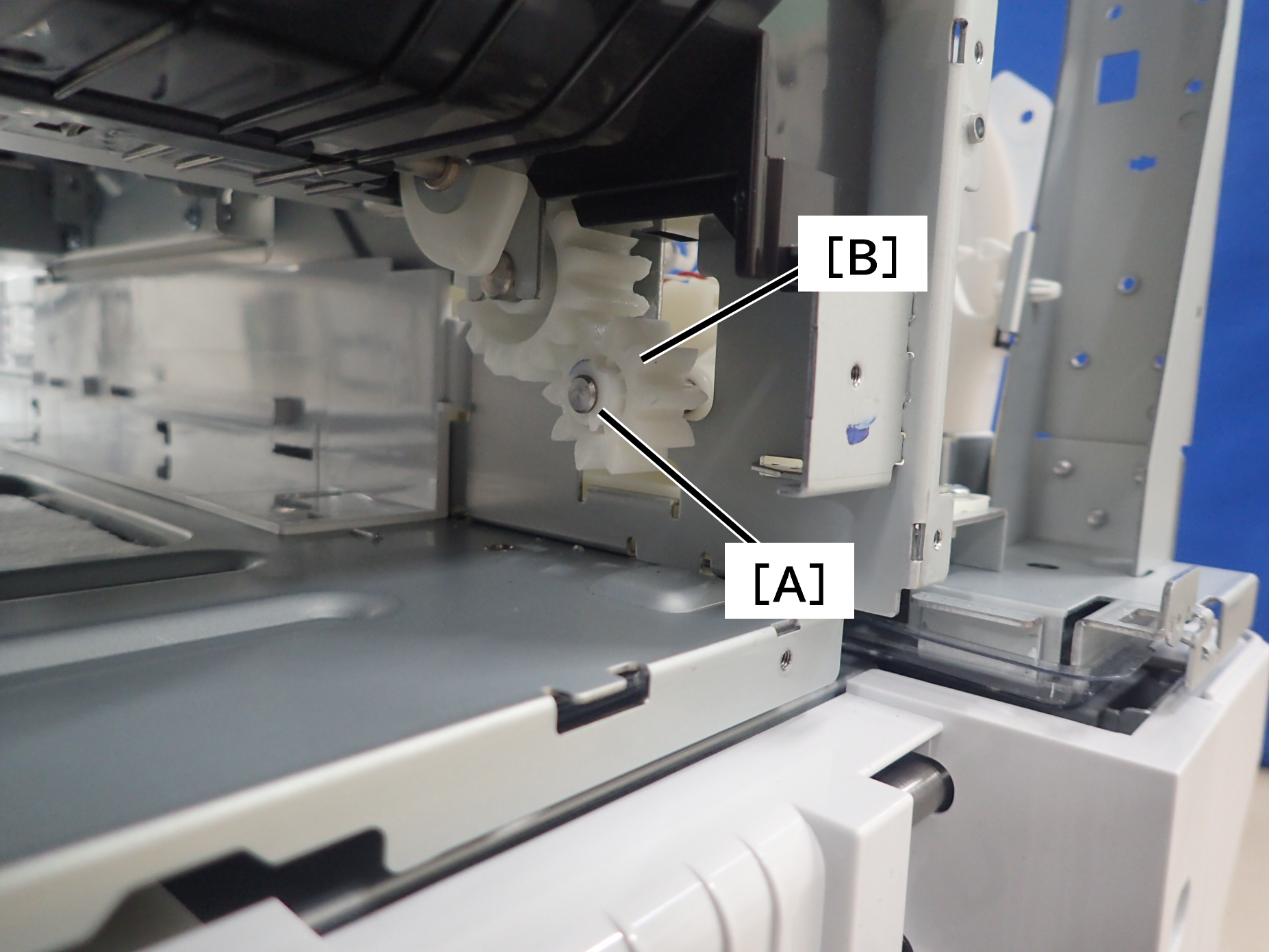
- Disconnect the connectors (A) to (D) in the illustration, and release the cable from the Lift Drive Assy.

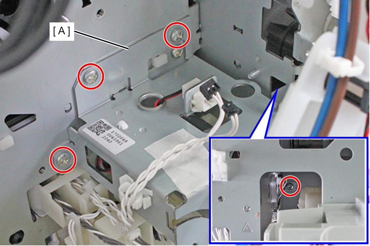
- Remove the three screws, then remove the Lift Drive Assy (A).
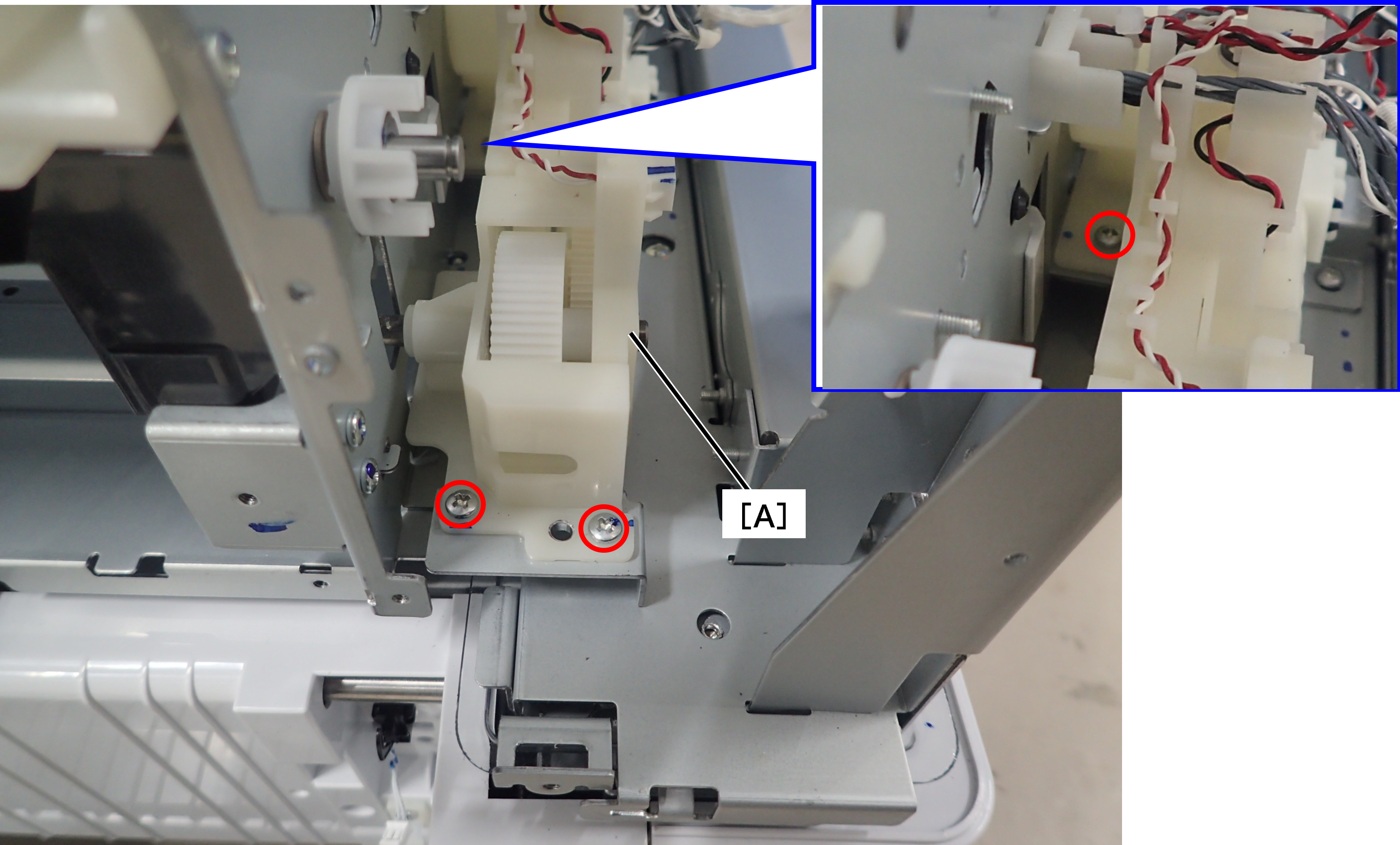 C.B.S-TITE-SCREW-3x8-F.ZN-3C
| Adjustment / 調整 |
After replacing this part, you need to run the menu from the service support mode. (If you ran the Before-replacement menu before replacing the part, it will start automatically when you turn the power on.) |