
Print position offset in CR operation direction
Symptom
- The image is offset in the main scanning direction (left and right margins are not equal).
- Left or right edge of the image is cut off.
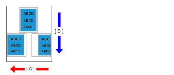
- A: Main scanning line (CR operation) direction
- B: Sub scanning line (feed) direction
Suspected cause
- Paper load position offset
- The paper settings of main unit or printer driver are not appropriate.
- Print start position adjustment value deviation
- PW sensor is dirty or has deteriorated.
- PW Sensor adjustment value incorrect
- CR Scale dirty, damaged, or defective
Troubleshooting
| Step | Check and measure | Yes | No |
|---|---|---|---|
| 1 | Check the paper cassette Check that the paper size and guide position are appropriate. |
Go to step 2 |
Correct the guide position. |
| 2 | Check the settings Check the settings of the main unit/printer driver listed below.
Are the printer/driver settings appropriate? |
Go to step 3 |
Change the settings. |
| 3 | Check the print start position process adjustment value Check that the print start position process adjustment value is appropriate. |
Go to step 4 | Enter an appropriate value from the adjustment pattern. |
| 4 | Check PW sensor (Execute the following item from the service support mode.)
|
Go to step 5 | If trouble is occurred in “1”, replace the PW sensor If the symptom continues to occur, go to step 5. |
| 5 | Check the rollers Check that the surfaces and attachment states of the intermediate rollers and feed rollers are appropriate. |
Go to step 6 | Reattach the rollers. |
| 6 | Check the CR Scale Execute the following adjustment from the service support mode.
Nozzle condition is excellent? |
Contact Epson local service representatives. |
|