
MB CSIC Assy
- Remove one screw.
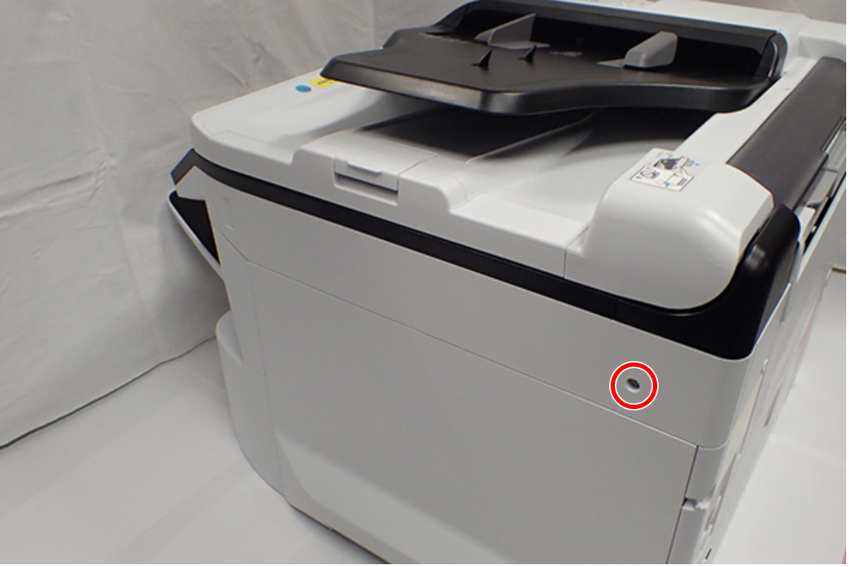
 : C.B.S-TITE-SCREW-3x8-F.ZN-3C
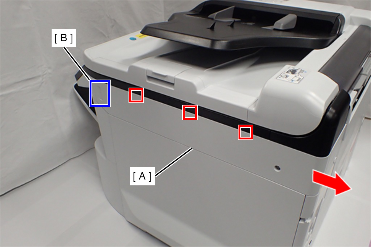
- Slide the Right SC Cover (A) while pushing the dent (B) of Right SC Cover, and release the three tabs. Remove the Right SC Cover (A).
- Remove one screw.
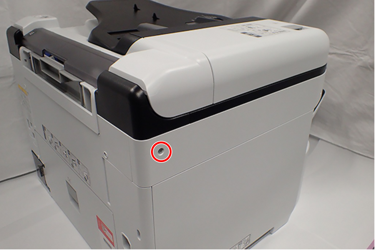
- : C.B.S-TITE-SCREW-3x8-F.ZN-3C
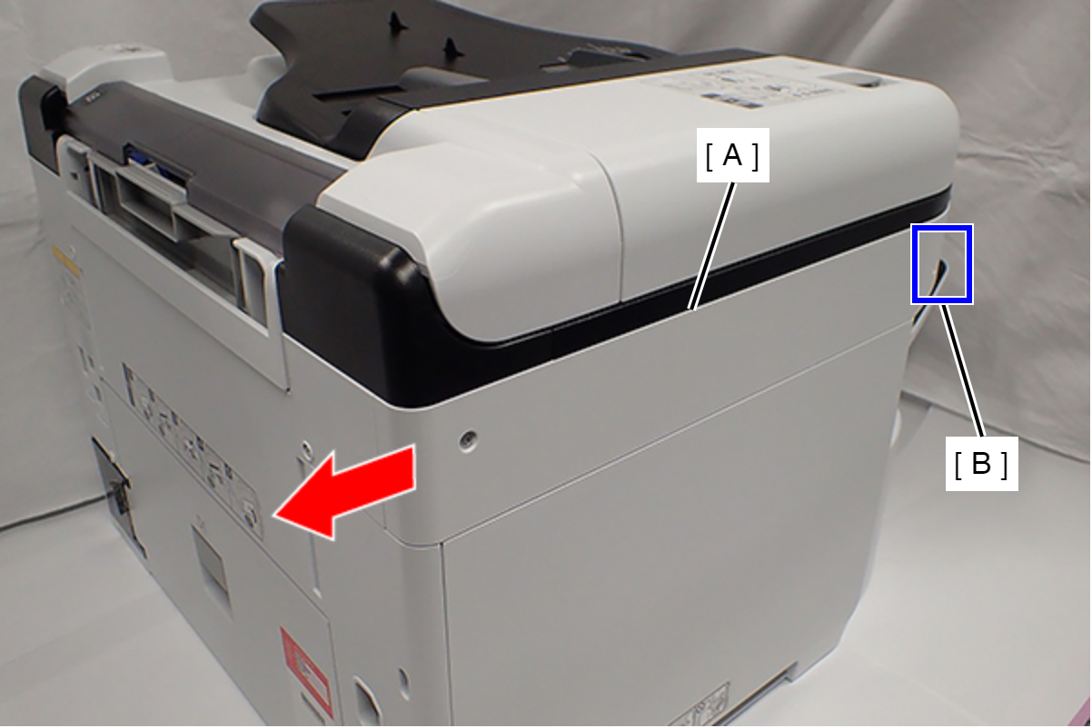
- Slide the Left SC Cover (A) while pushing the dent (B) of Left SC Cover, and remove it.
- Remove one screw, and remove the Lower SC Reinforcing Plate (A).
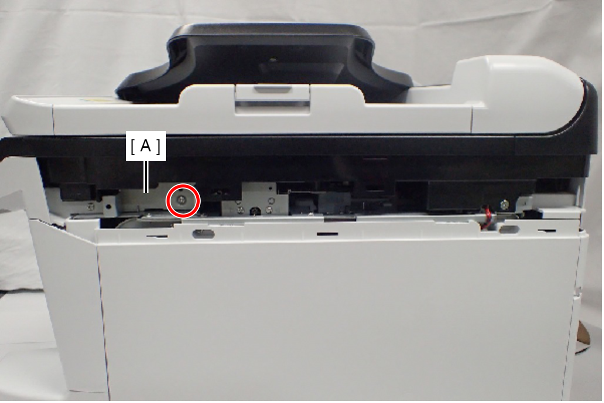
- : C.B.S-TITE-SCREW-3x8-F.ZN-3C
- Reattach the Lower SC Reinforcing Plate (A) in its portrait orientation, then secure it with the screw.
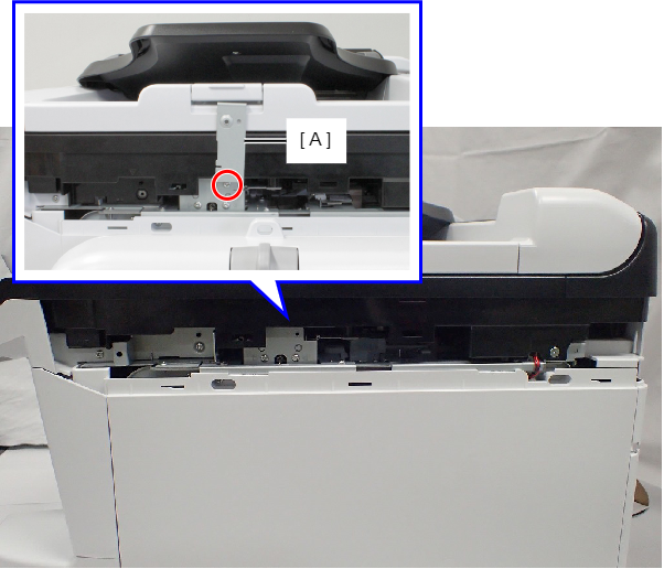
- : C.B.S-TITE-SCREW-3x8-F.ZN-3C
- Remove the screw.
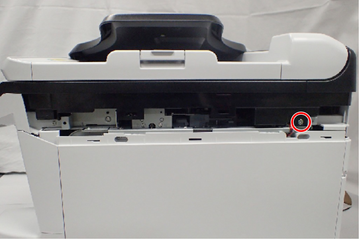
- : C.SHOULDER S-TITE,3X5
- Open the ADF/SCN Unit (A).
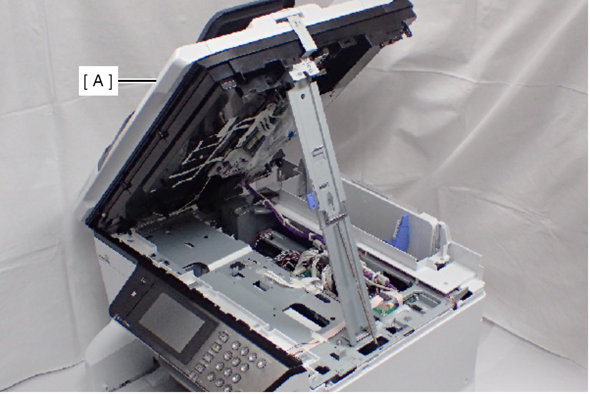
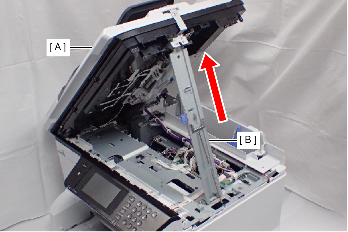
- Open the ADF/SCN Unit (A) and extend the support stand (B) as far as it goes, then support the ADF/SCN Unit with the support stand.
 Caution / 注意
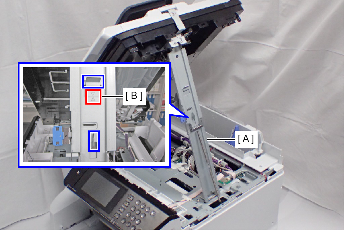
Make sure that the support stand (A) is fixed with the two hooks, and the two triangle marks (B) face to each other.
 Check Point / チェックポイント
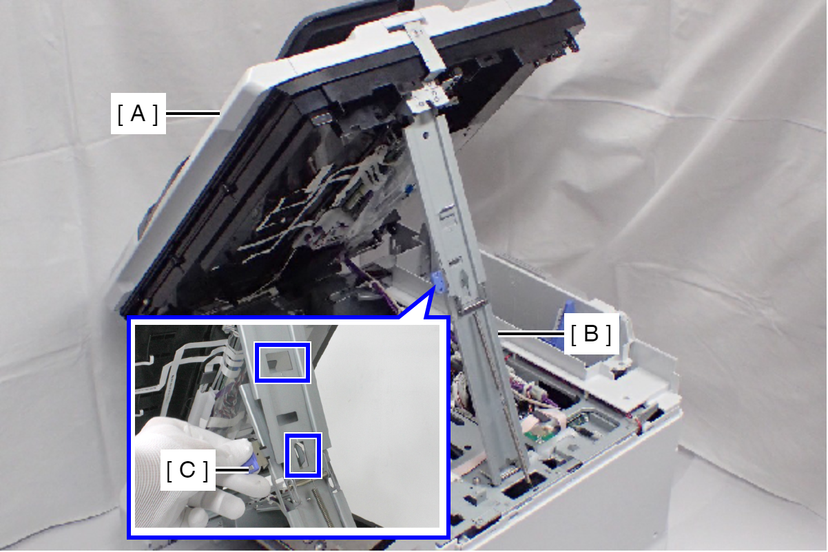
When closing the ADF/SCN Unit (A), press the switch (C) on the ADF/SCN support stand (B) and hold up the ADF/SCN Unit to disengage the two hooks, then fold the ADF/SCN support stand.
- Remove the screw.
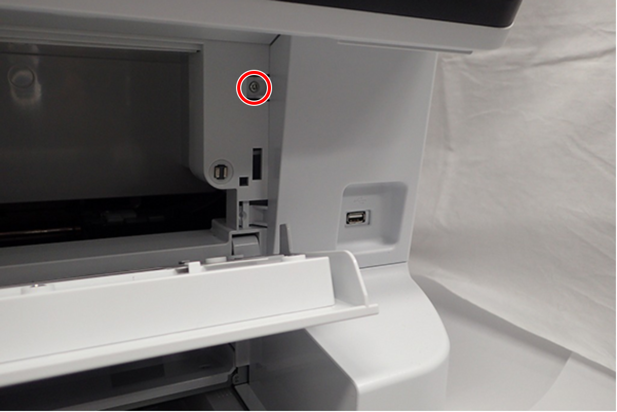
- : C.B.S-TITE-SCREW-3x8-F.ZN-3C
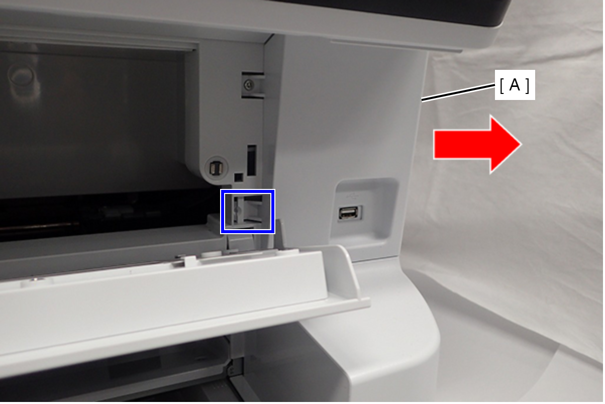
- Release the Hook, then slide the Front Right Cover (A) to direction of arrows and remove it.
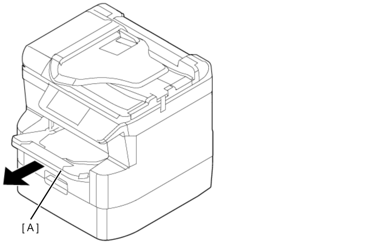
- Remove the Stacker Assy (A).
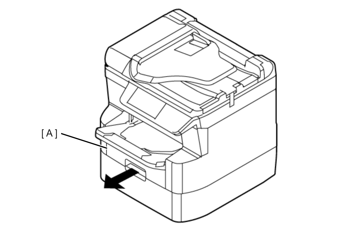
- Remove the Cassette Assy (A).
- Remove the two screws.
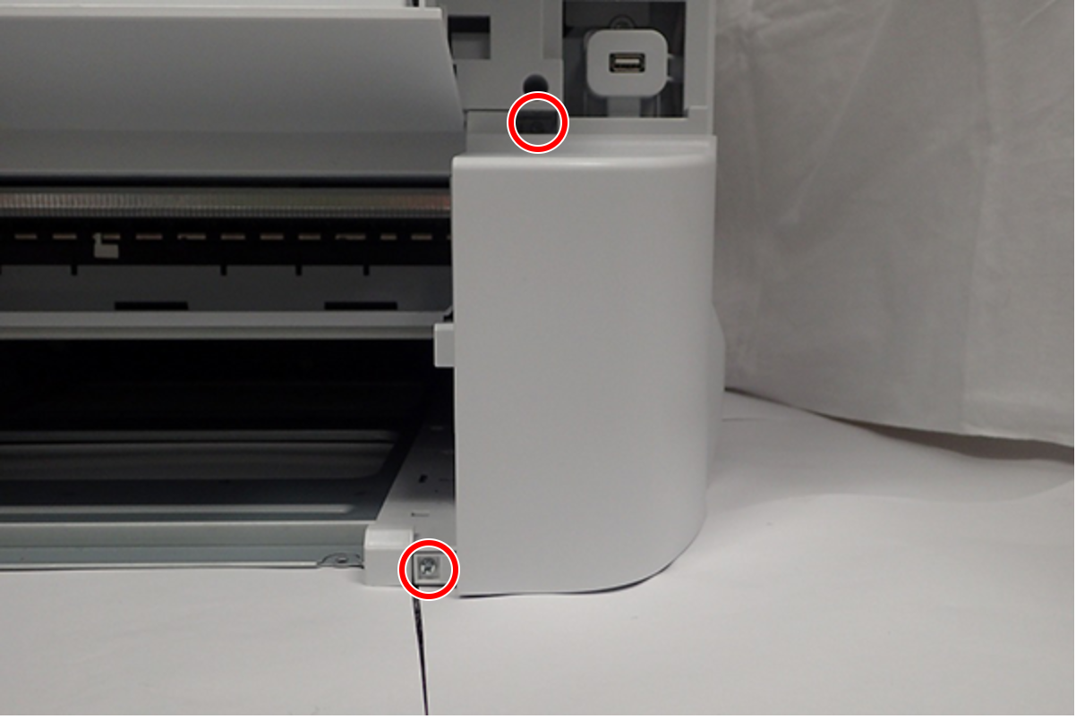
- : C.B.S-TITE-SCREW-3x8-F.ZN-3C
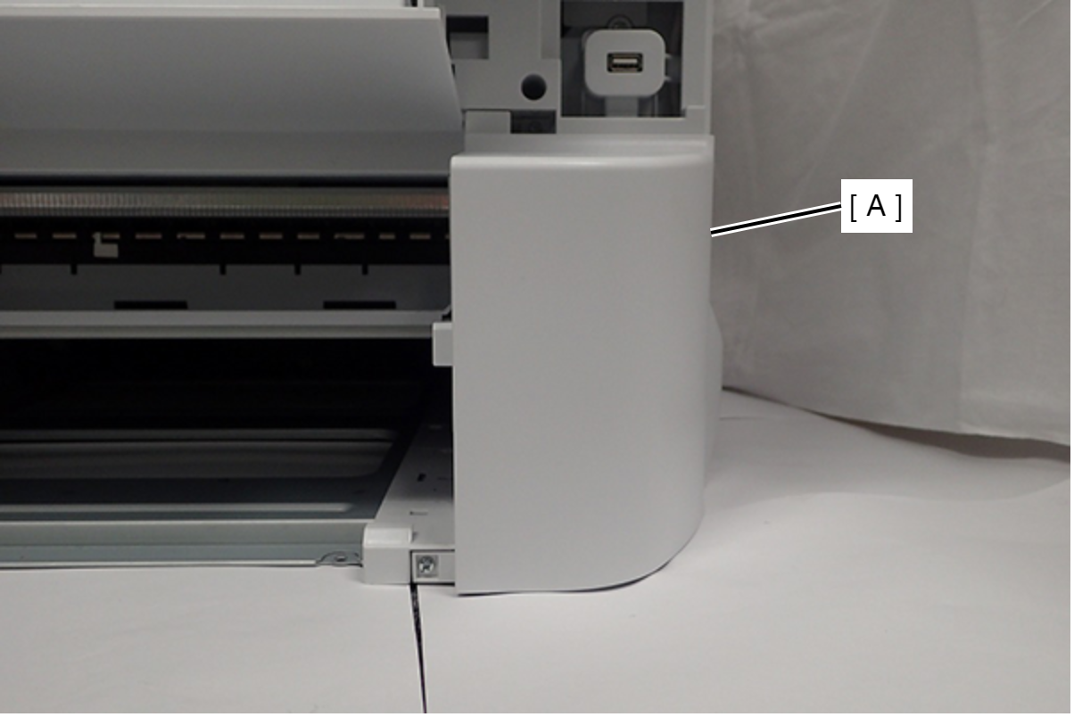
- Remove the Front Right Housing (A).
- Remove the four screws, then remove the Front Middle Frame (A).
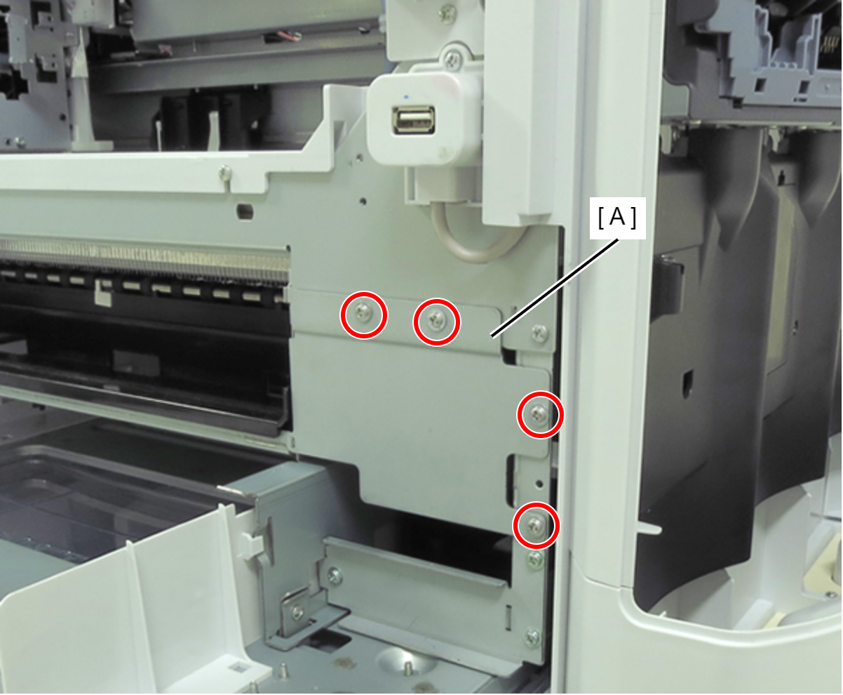
- : C.C.S-TITE-SCREW-3x5-F.ZN-3C
- Remove the four screws fastening the Right Housing (A).
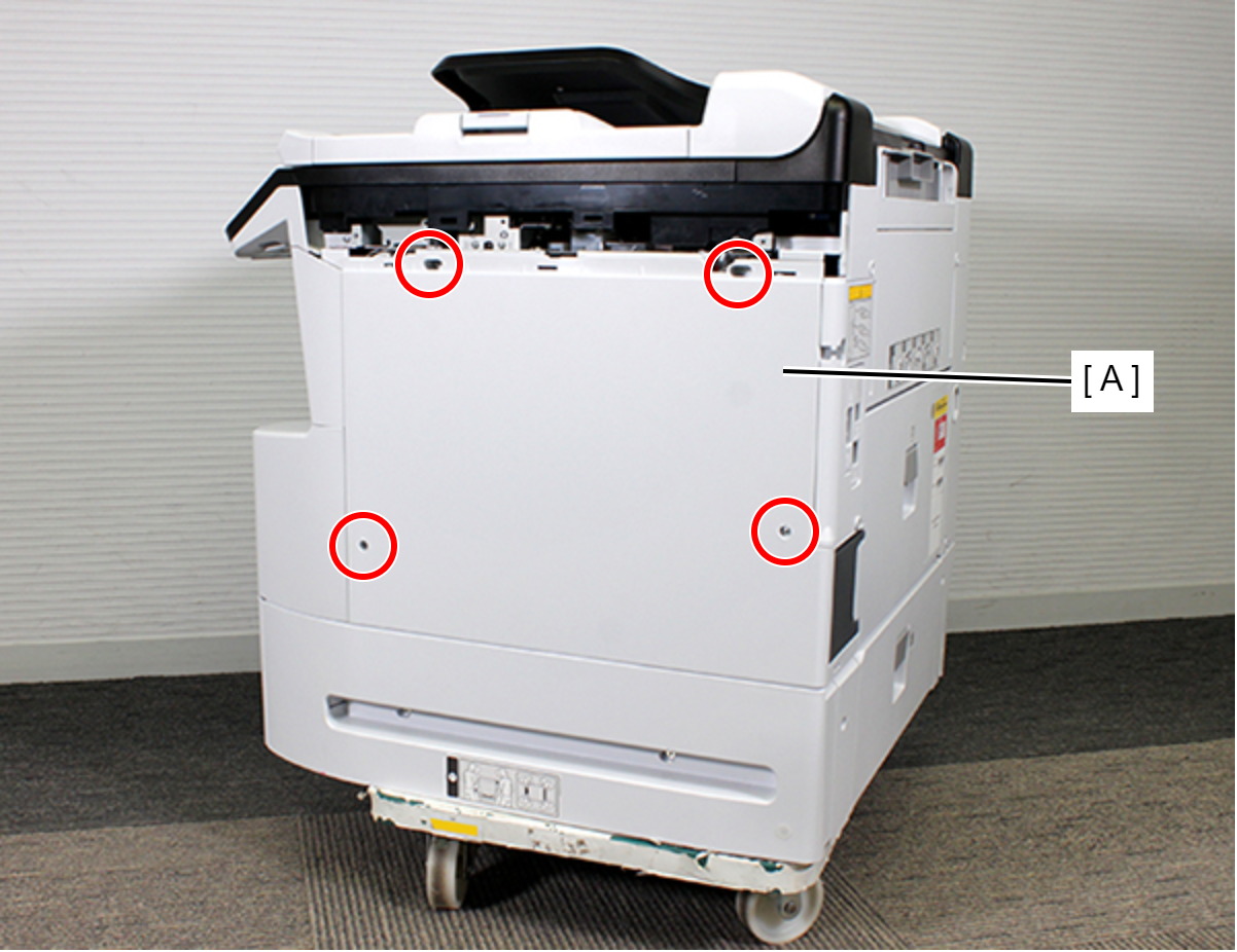
 : C.B.S-TITE-SCREW-3x8-F.ZN-3C
- Release the hook.
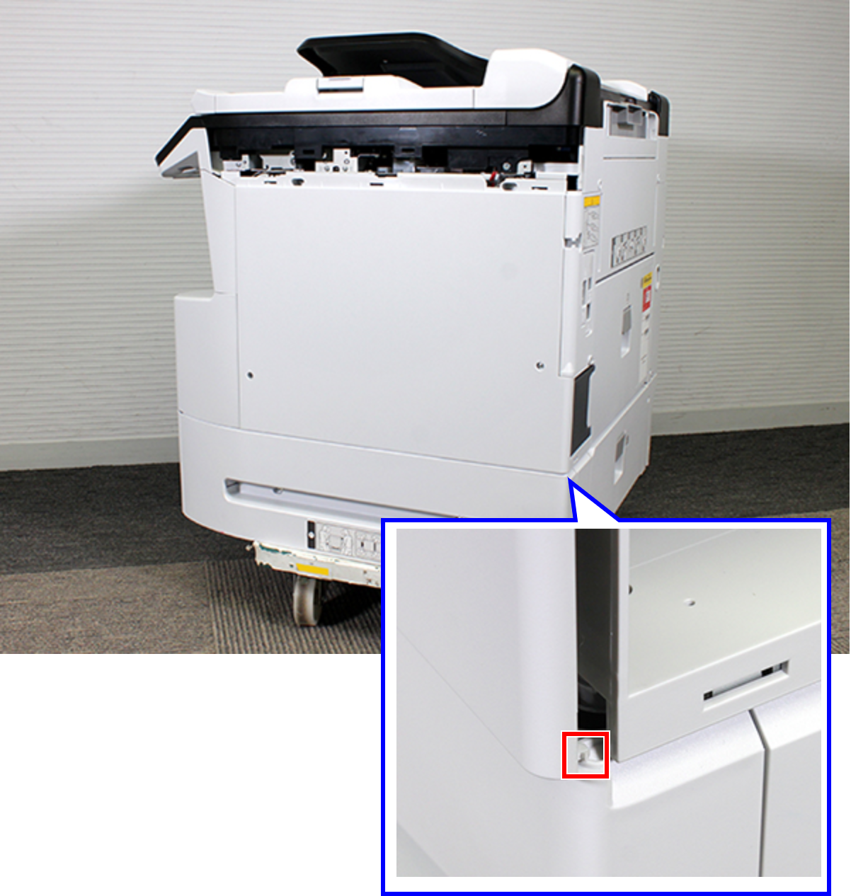
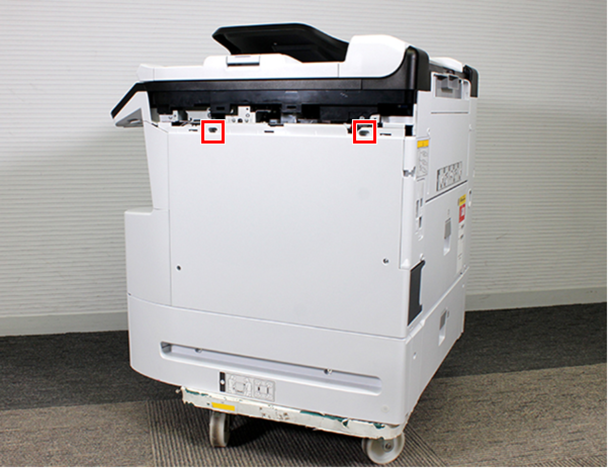
- Remove the two dowels.
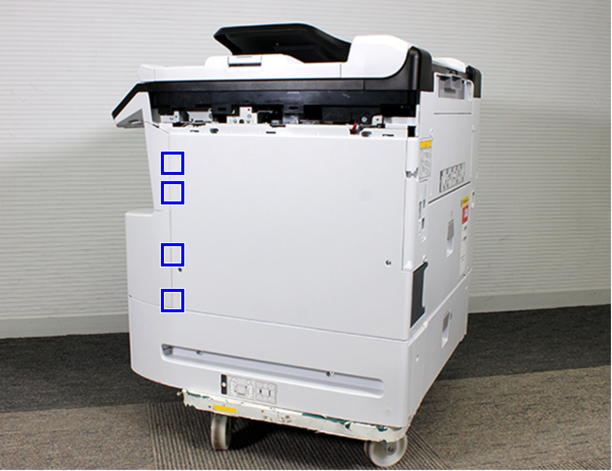
- Release the four hooks.
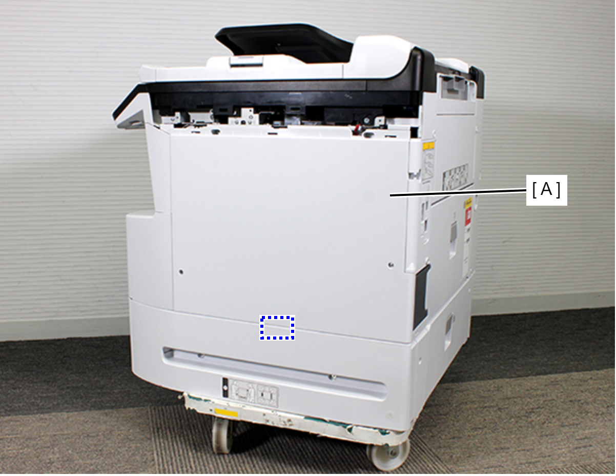
- Remove the Right Housing (A) while removing the rib.
- Remove the screw, then remove the IS Holder Plate (A) in the direction of the arrow.
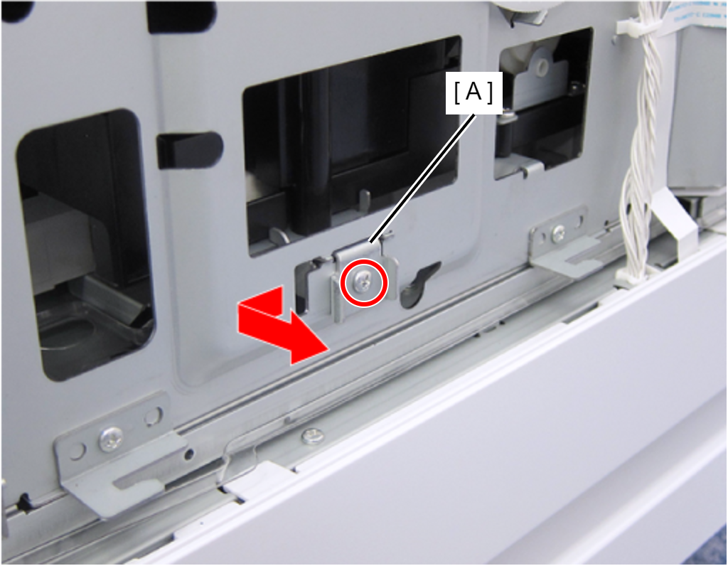
- : C.B.S-TITE-SCREW-3x8-F.ZN-3C
- Insert the screwdriver into the hole and turn each of the two screws that secure the Ink System Assy (A) until you feel the screw is spinning free.
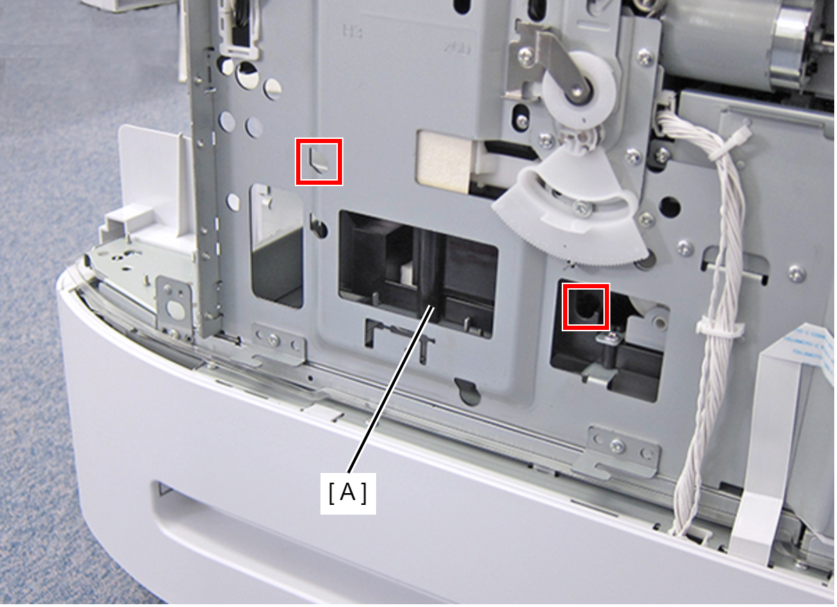 Check Point / チェックポイント
- Release the CR lock, then move the CR Unit to center before removing the Ink System Assy.
- The screws are not removed because there is a screw clamp.
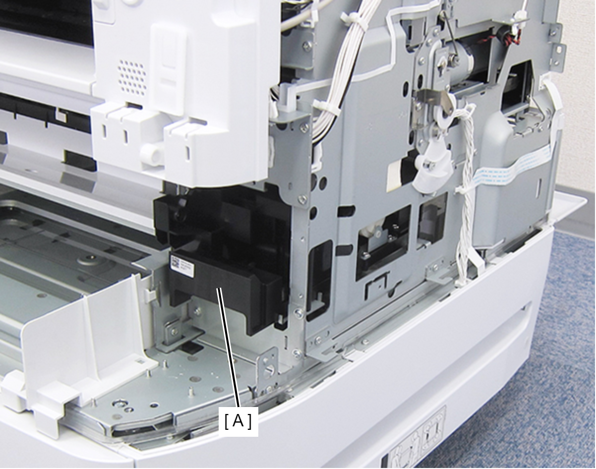
Pull the Ink System Assy (A) forward.
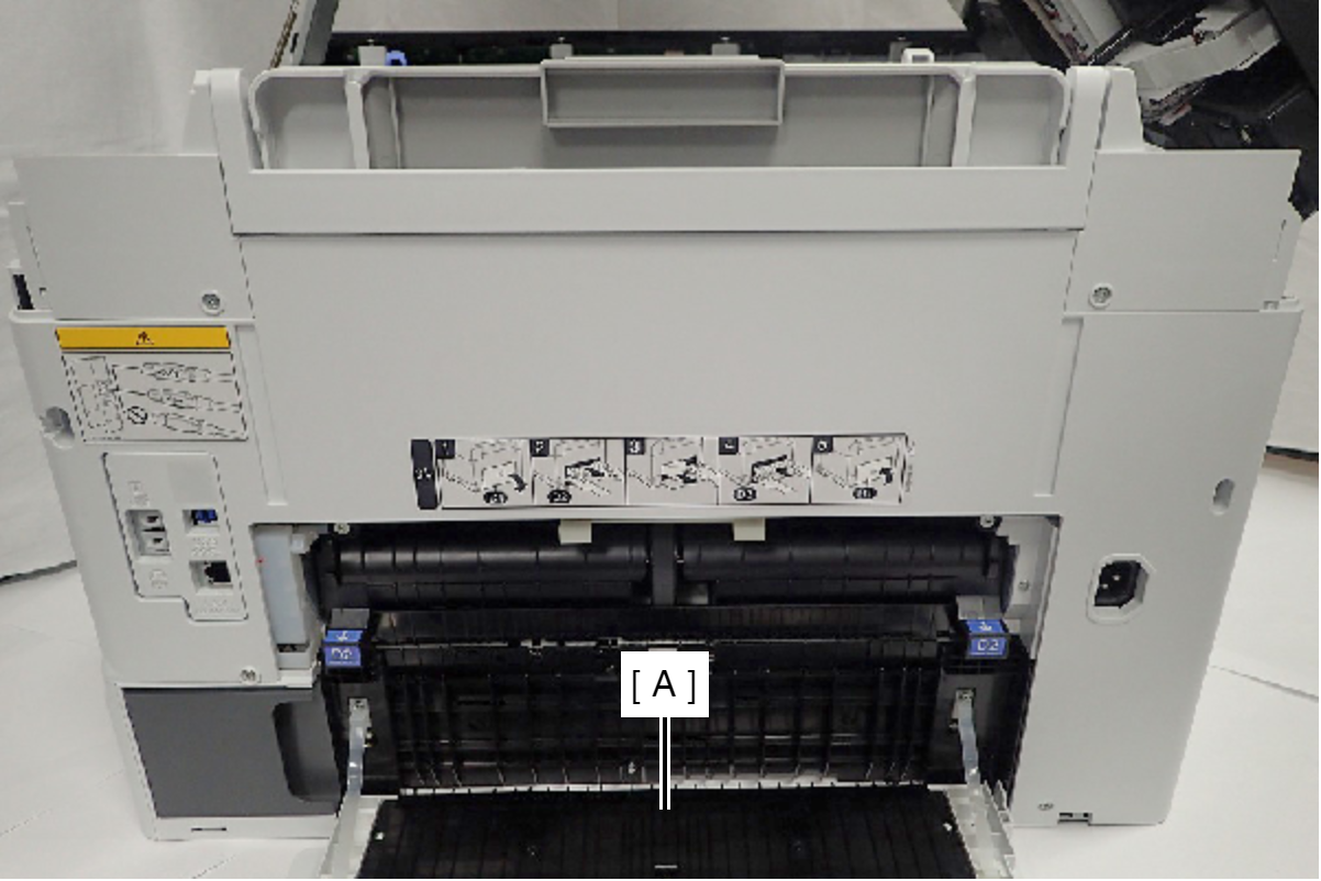
- Open the Duplex Print Cover (A).
- Remove the seven screws.
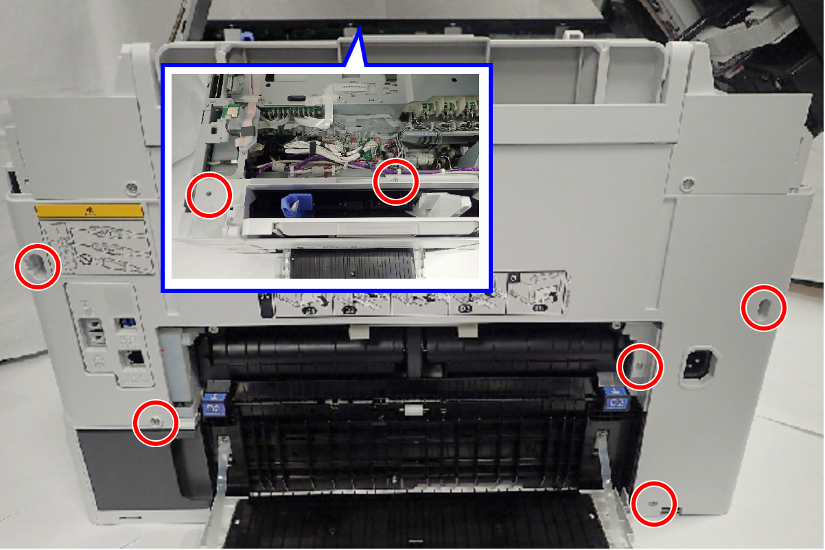
- : C.B.S-TITE-SCREW-3x8-F.ZN-3C
- Press the Rear Housing Assy (A) in the direction of the arrow, then release the hook.
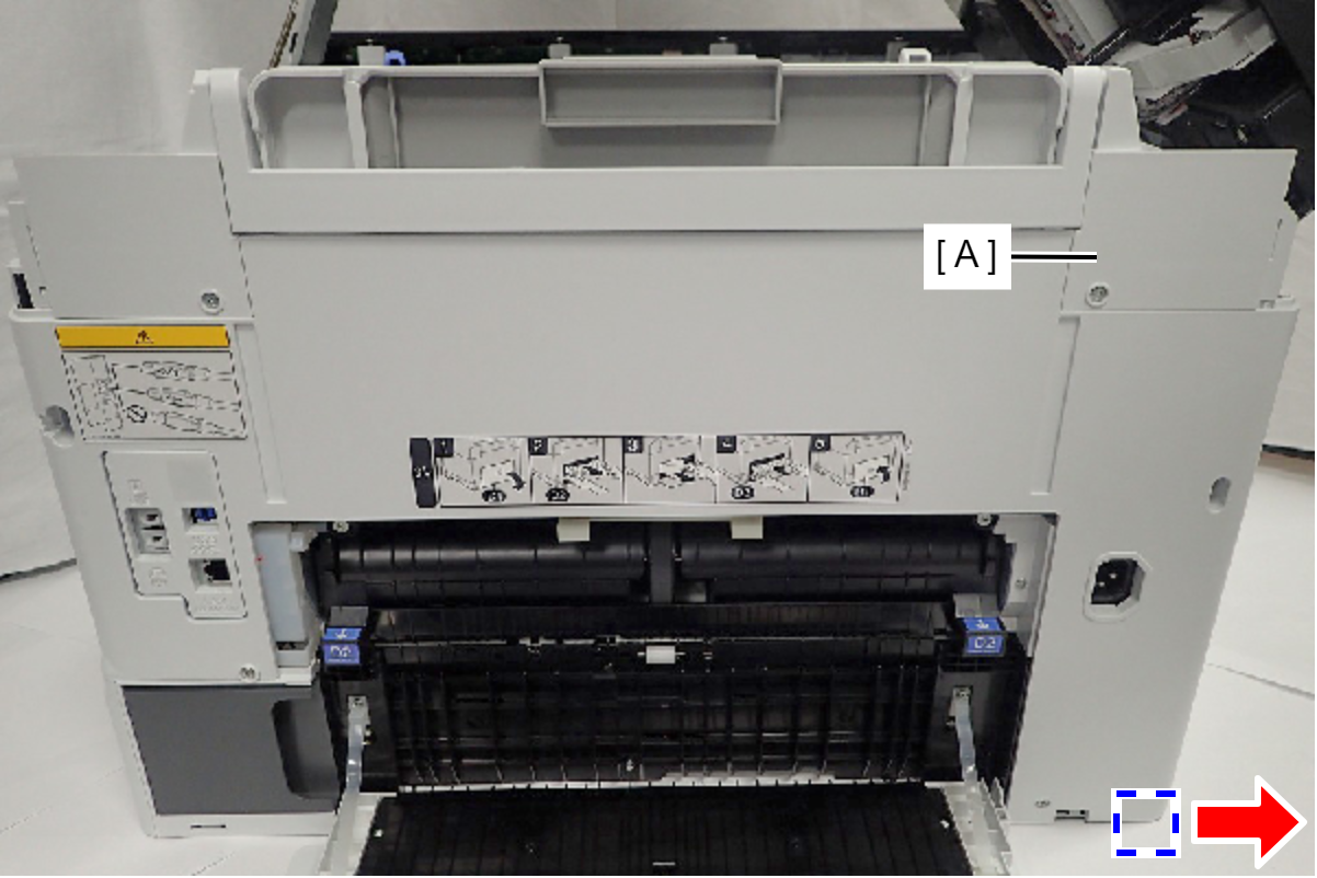
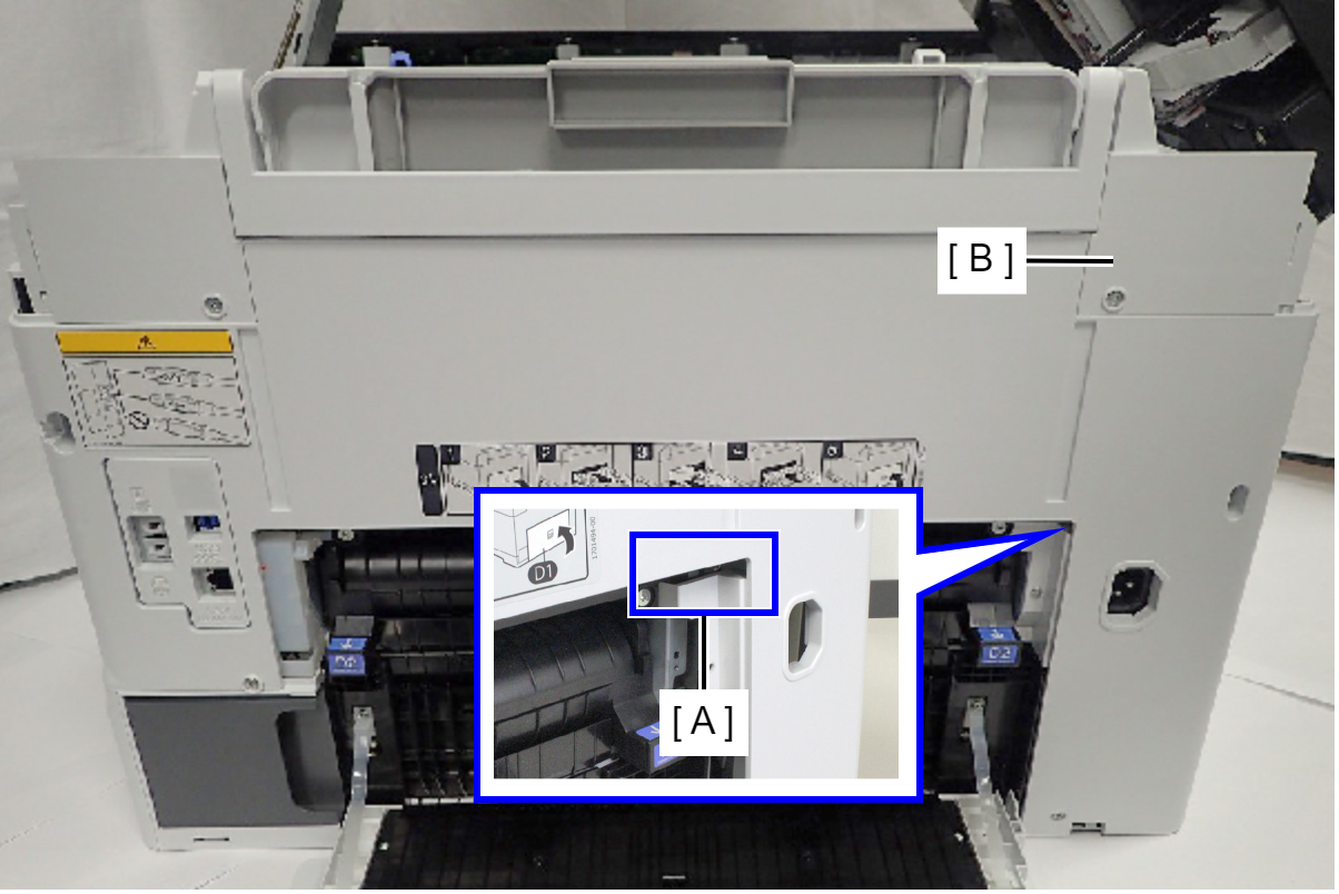
- Remove the Rear Housing Assy (B) while releasing the place interfering with the Rear ASF Unit (A).
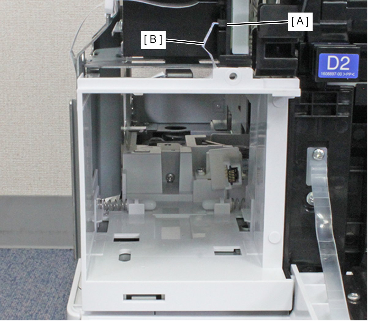
- Remove the MB CSIC FFC (B) from the connector (CN707) (A) of the Main Board.
Remove the screw.
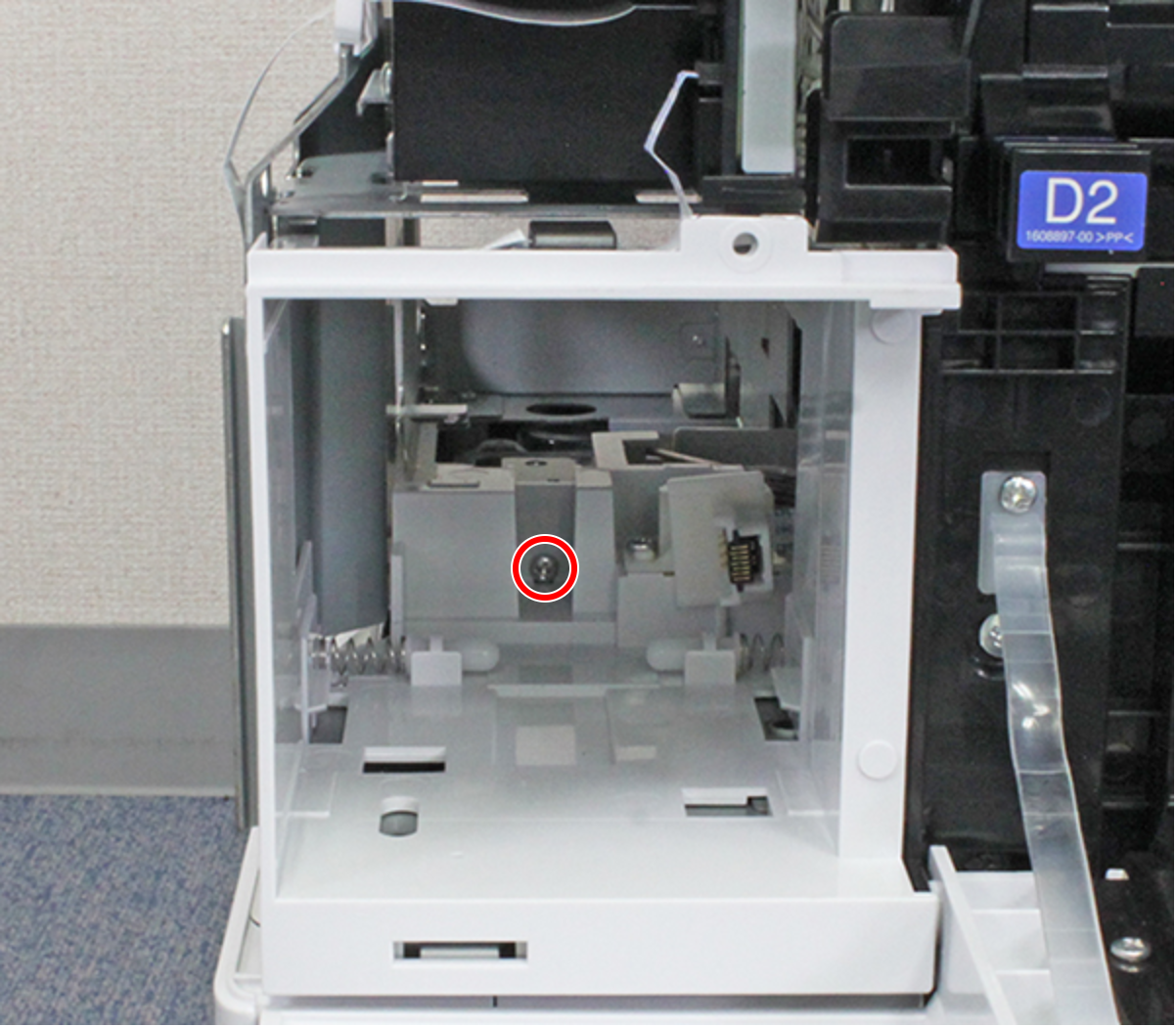
- : C.B.S-TITE-SCREW-3x8-F.ZN-3C
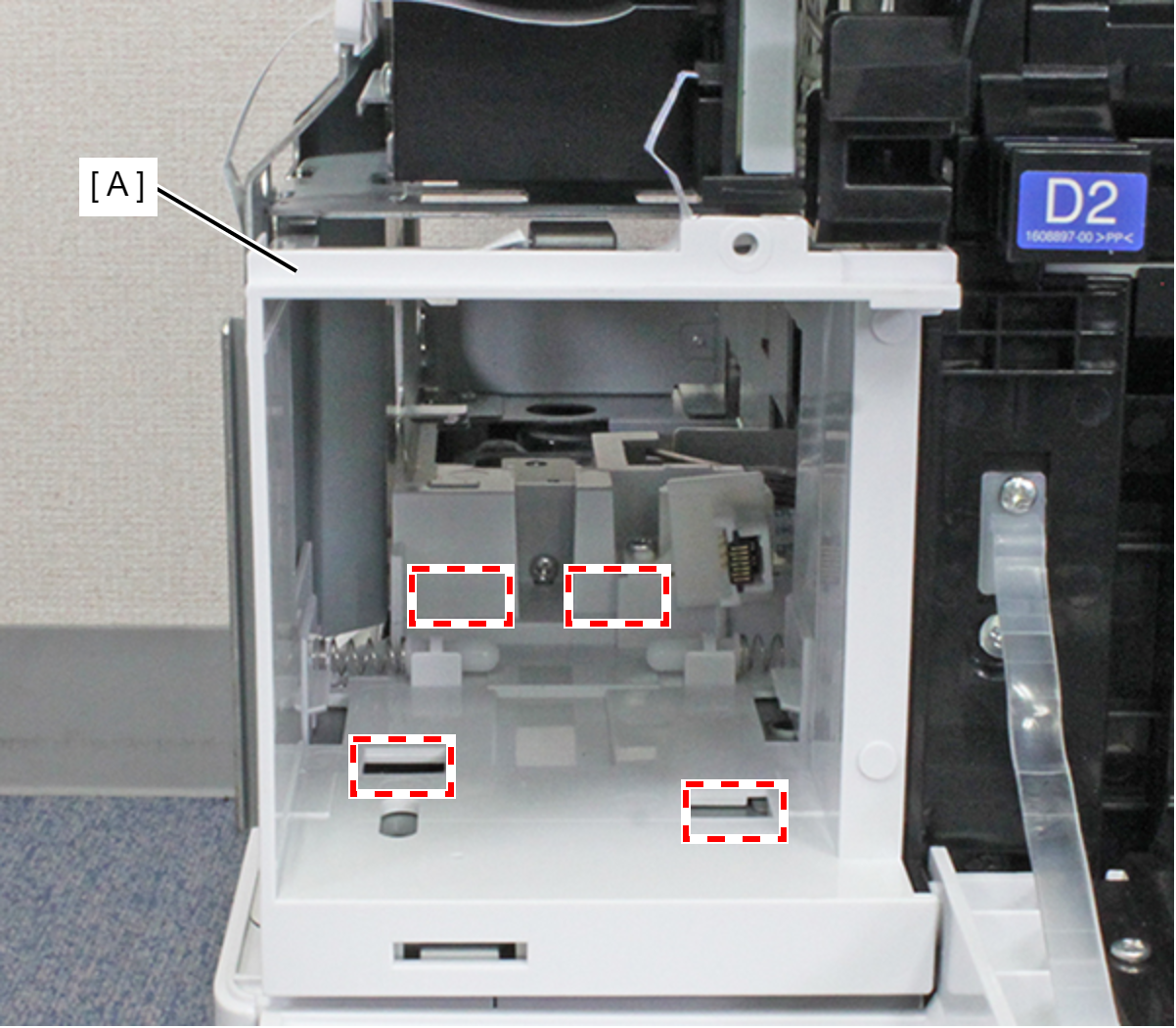
- Release the four hooks by pulling the Maintenance Box Holder Assy (A) toward the rear of the product, and remove the Maintenance Box Holder Assy (A).
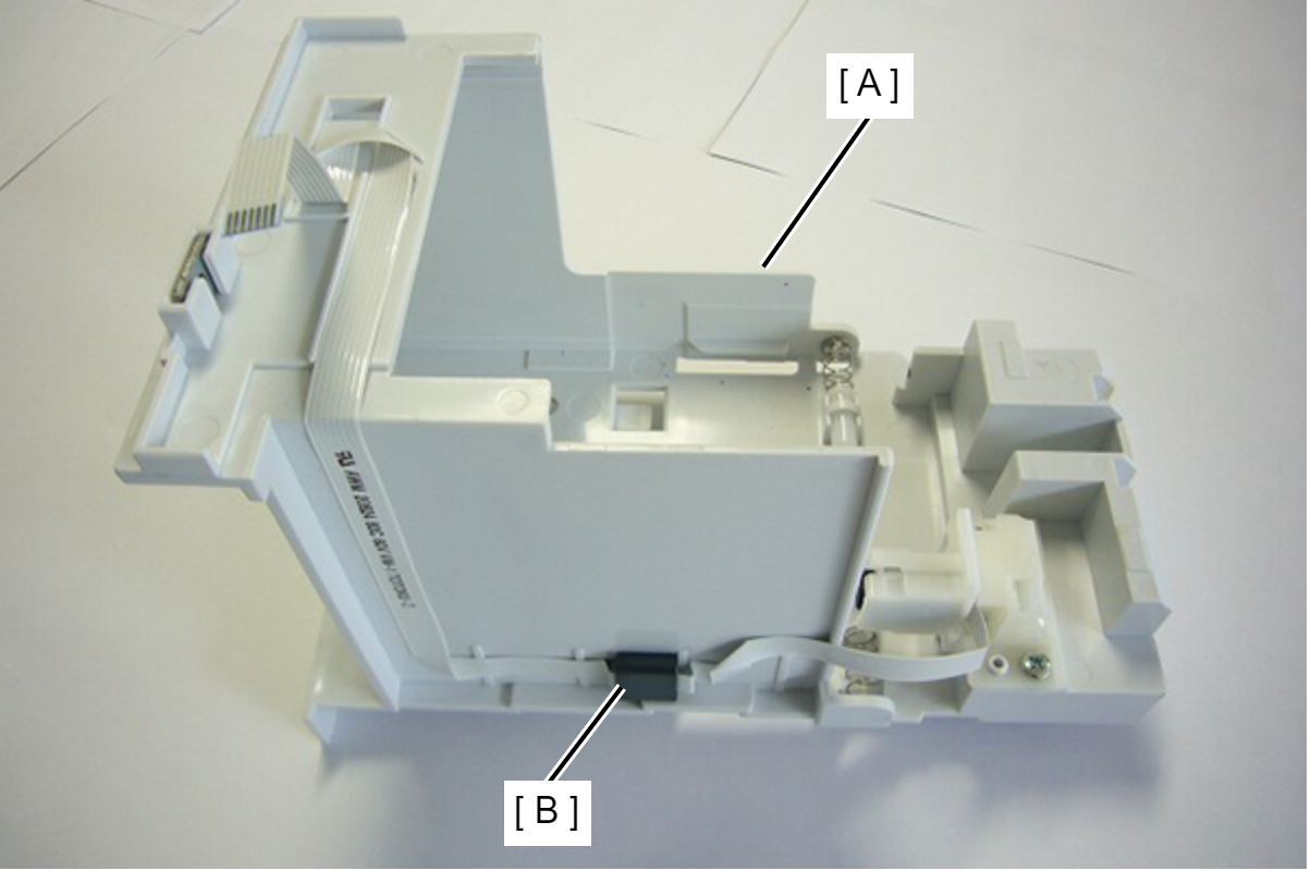
- Remove the FFC and the ferrite core (B) from the Maintenance Box Holder (A).
- Remove the two screws, then remove the MB CSIC Assy (A).
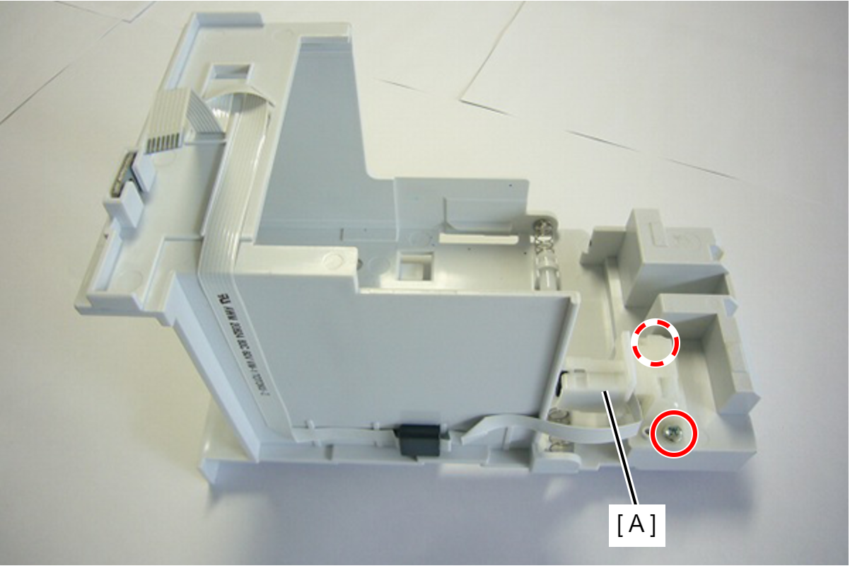
- : C.B.P-TITE-SCREW-3x10-F.ZN-3C