
Nip Release Solenoid
 Adjustment / 調整 Adjustment / 調整 |
When replacing this part, you need to run the menu from the service support mode before replacing it. |
- Remove one screw.
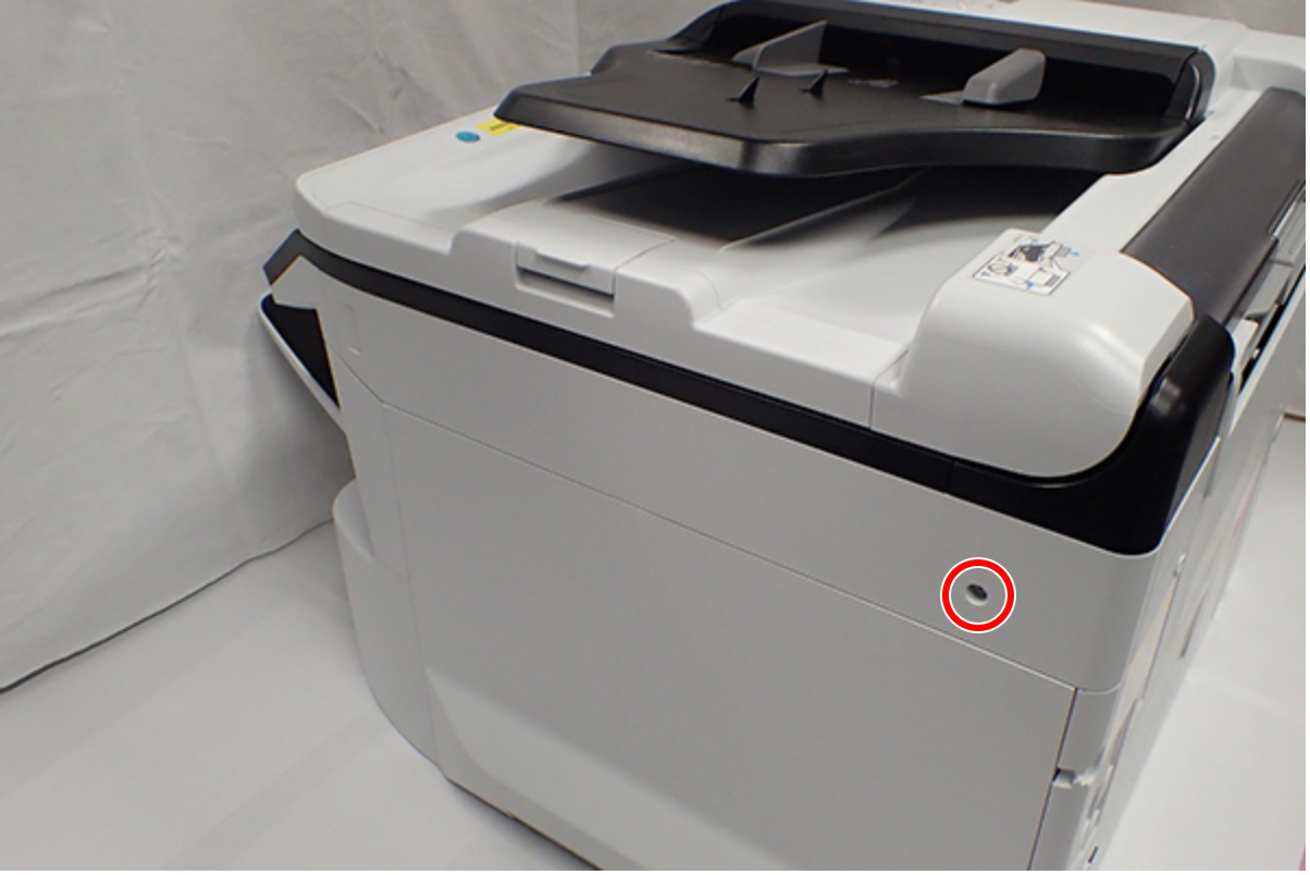
 : C.B.S-TITE-SCREW-3x8-F.ZN-3C
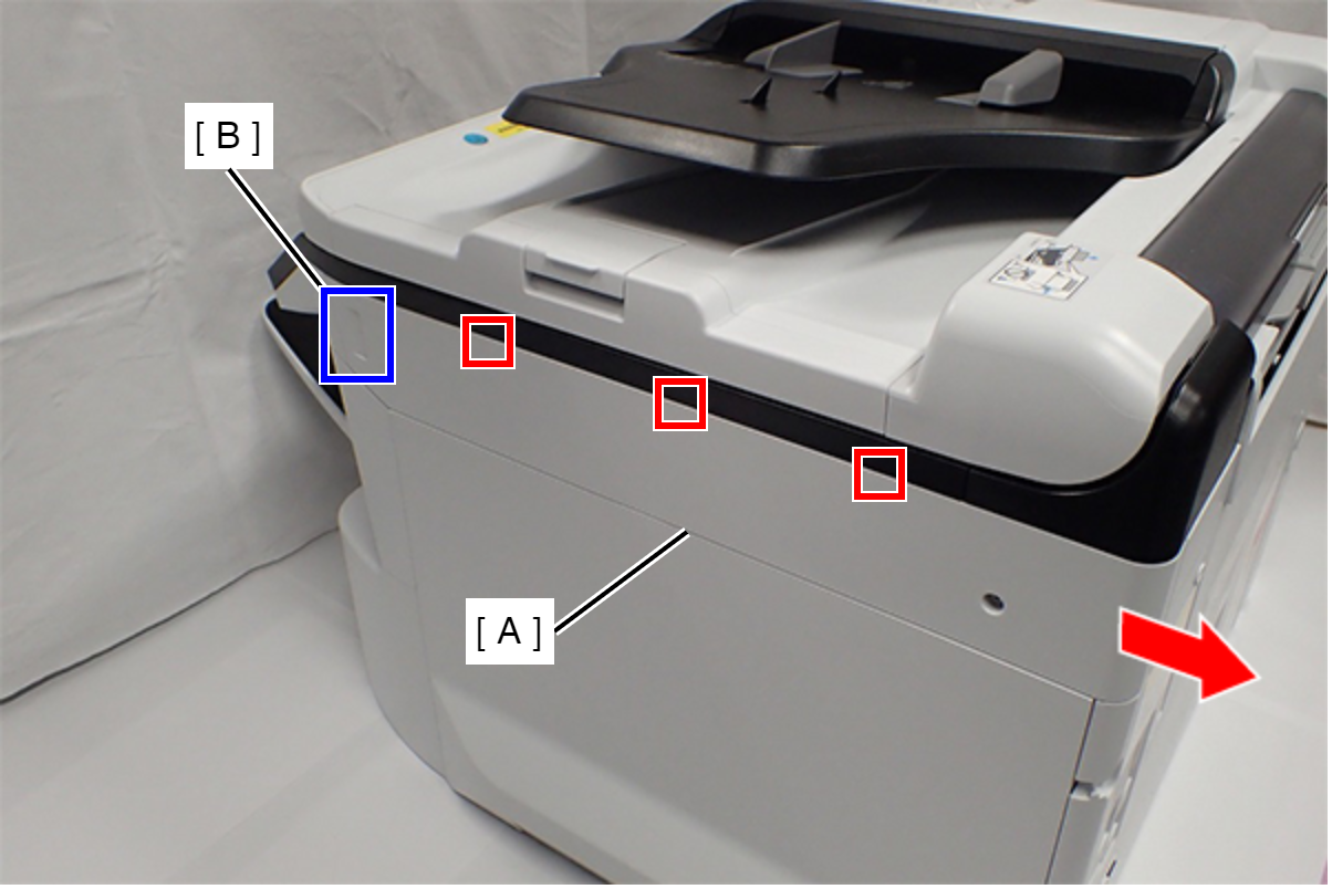
- Slide the Right SC Cover (A) while pushing the dent (B) of Right SC Cover, and release the three tabs. Remove the Right SC Cover (A).
- Remove one screw.
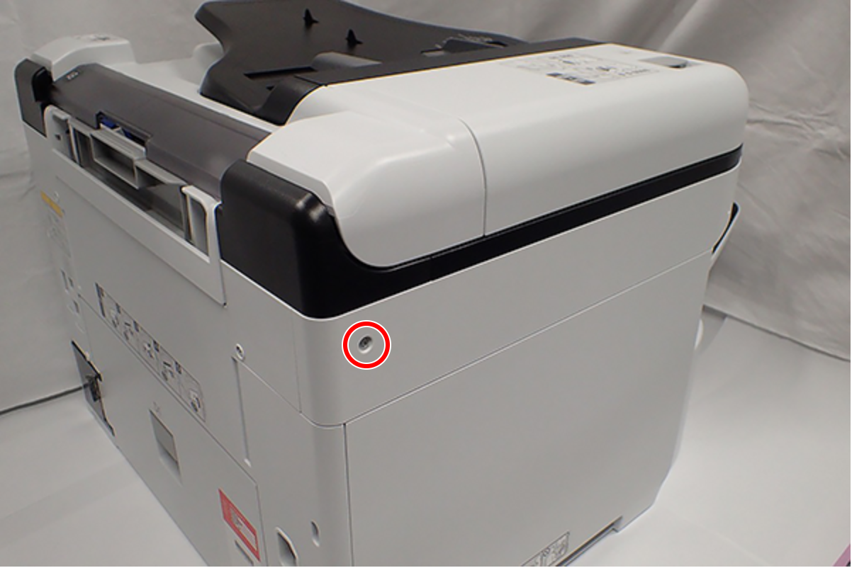
- : C.B.S-TITE-SCREW-3x8-F.ZN-3C
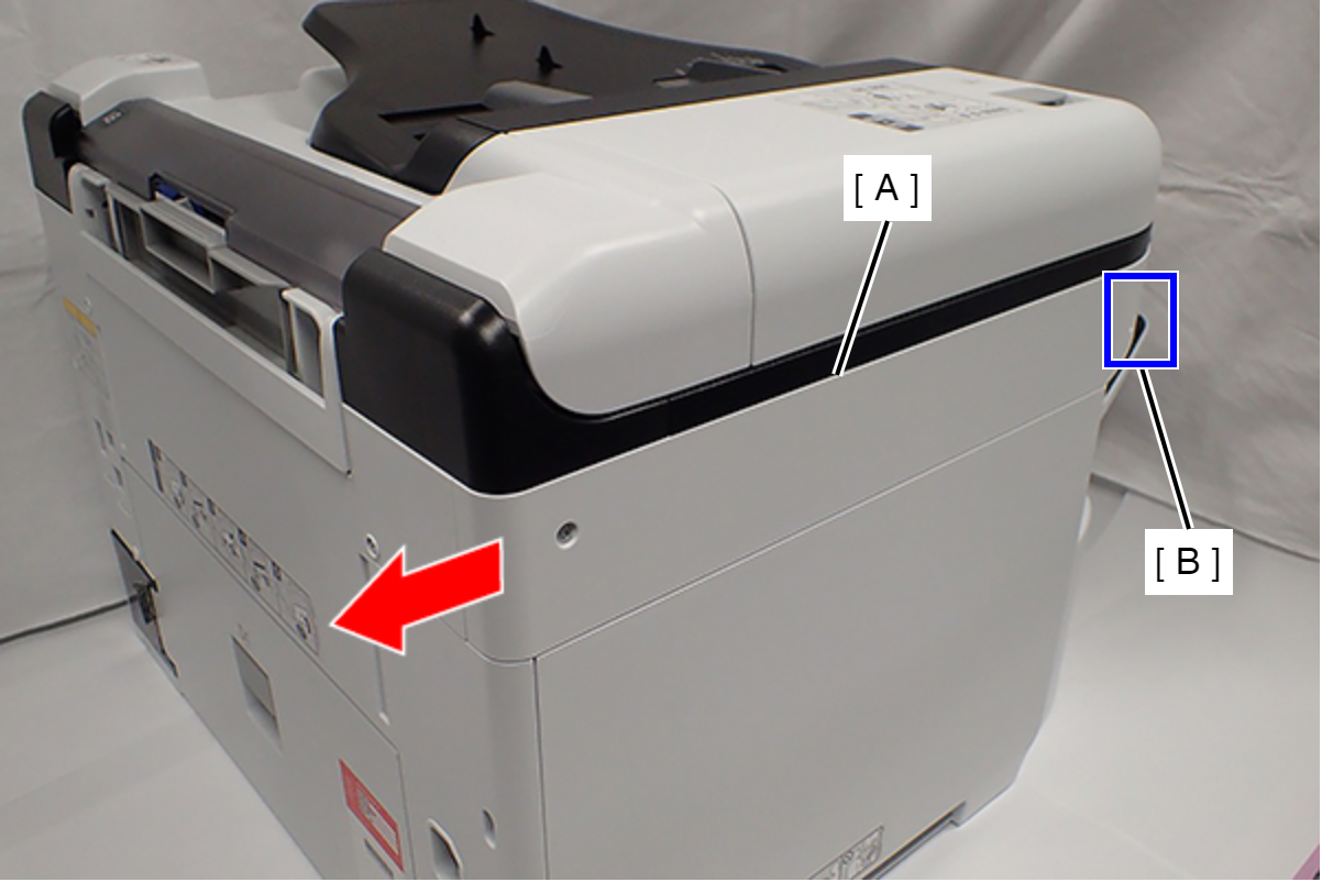
- Slide the Left SC Cover (A) while pushing the dent (B) of Left SC Cover, and remove it.
- Remove one screw, and remove the Lower SC Reinforcing Plate (A).
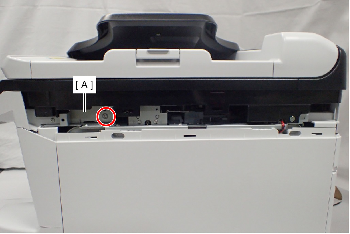
- : C.B.S-TITE-SCREW-3x8-F.ZN-3C
- Reattach the Lower SC Reinforcing Plate (A) in its portrait orientation, then secure it with the screw.
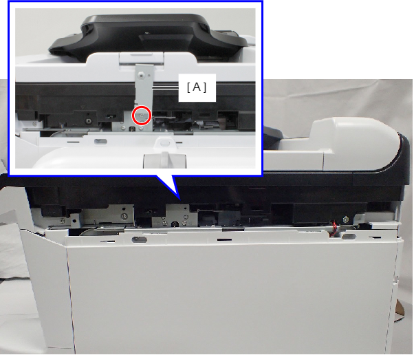
- : C.B.S-TITE-SCREW-3x8-F.ZN-3C
- Remove the screw.
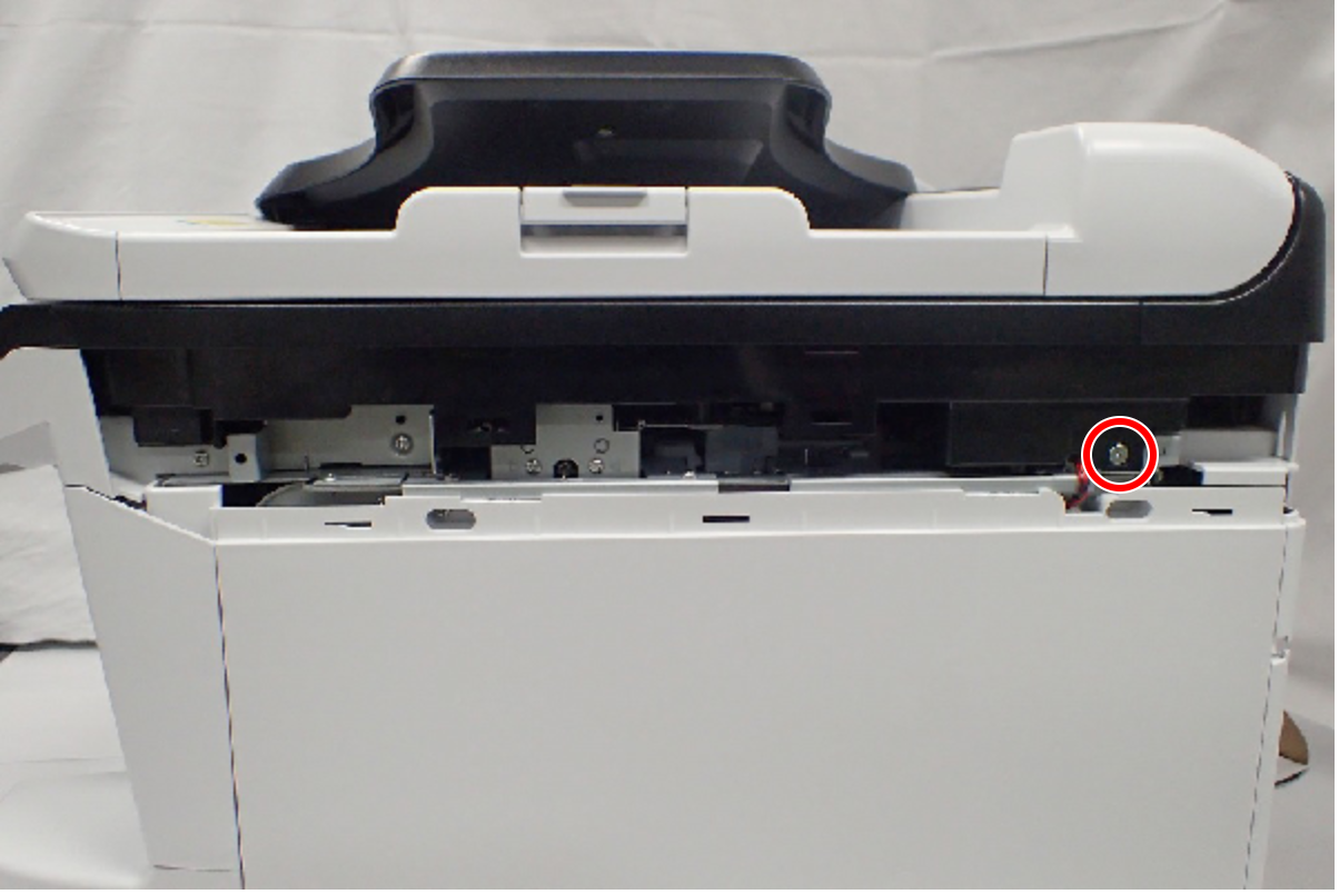
- : C.SHOULDER S-TITE,3X5
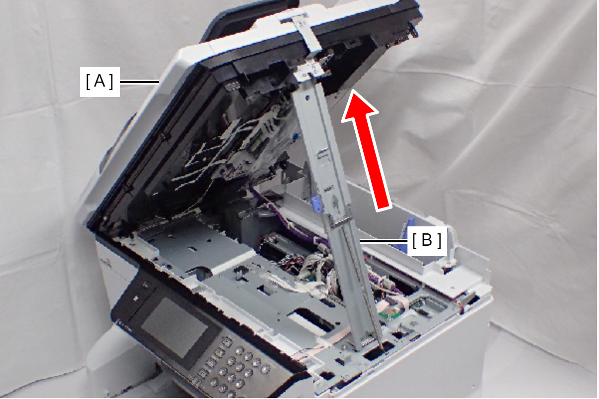
- Open the ADF/SCN Unit (A).
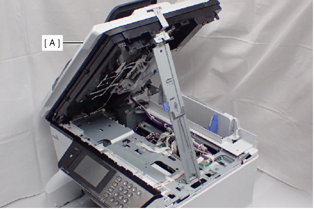
- Open the ADF/SCN Unit (A) and extend the support stand (B) as far as it goes, then support the ADF/SCN Unit with the support stand.
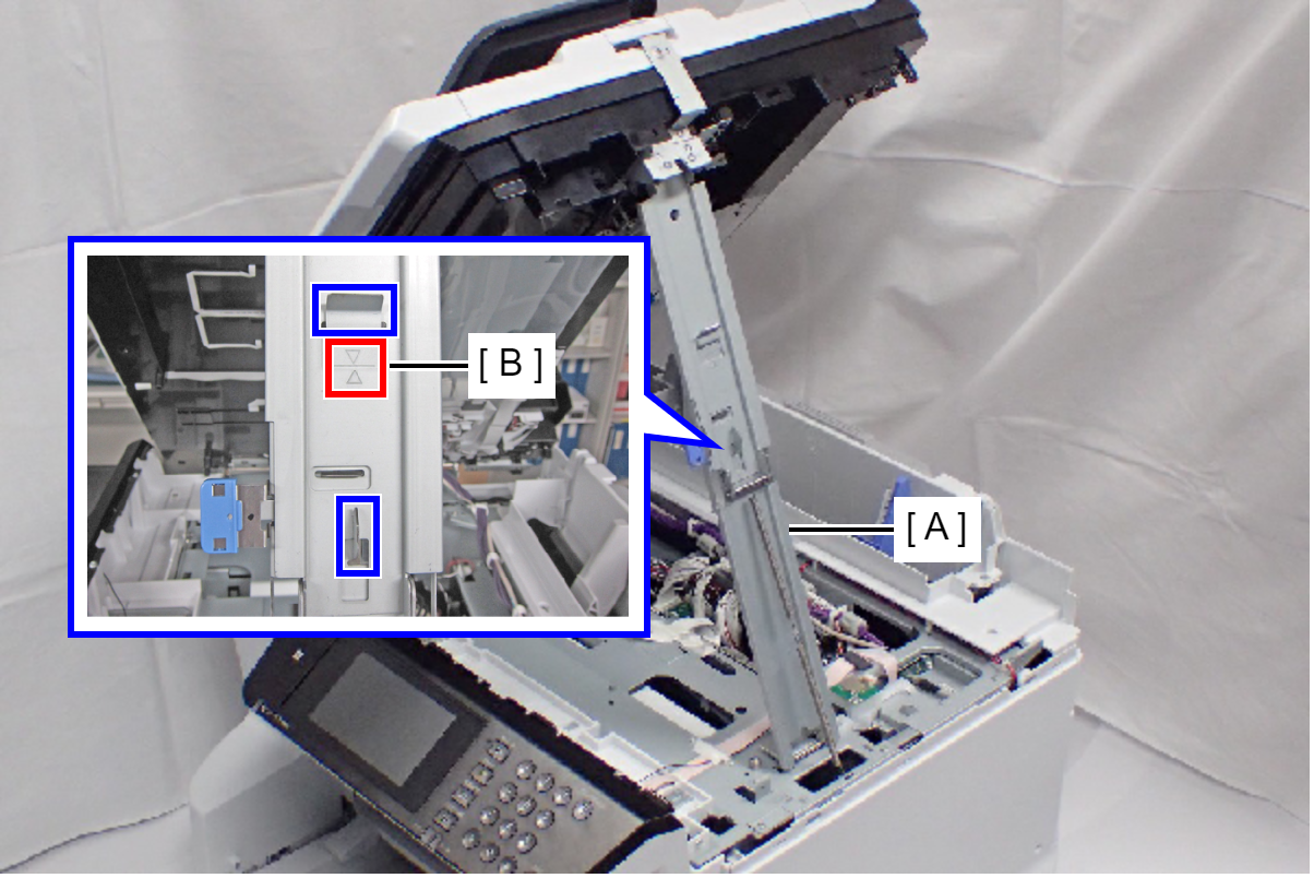
 Caution / 注意
Make sure that the support stand (A) is fixed with the two hooks, and the two triangle marks (B) face to each other.
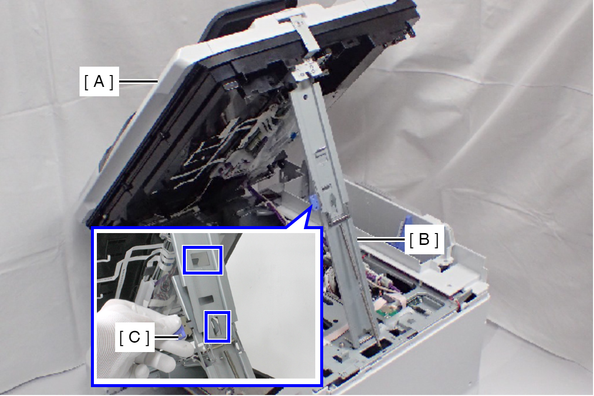
 Check Point / チェックポイント
When closing the ADF/SCN Unit (A), press the switch (C) on the ADF/SCN support stand (B) and hold up the ADF/SCN Unit to disengage the two hooks, then fold the ADF/SCN support stand.
- Release the ADF/SCN cable (A) from the hooks of the Relay Harness Cover (B).
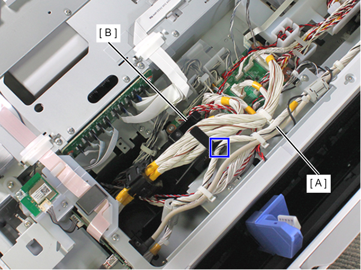
- Release the two relay cables (B) from the clamp (A).
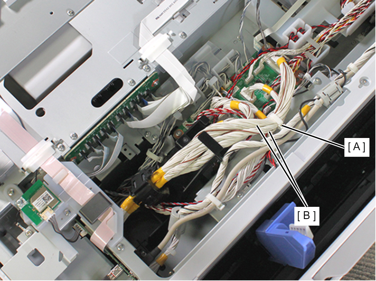
- Release the three relay cables (B) from the hooks of the Relay Harness Cover (A).
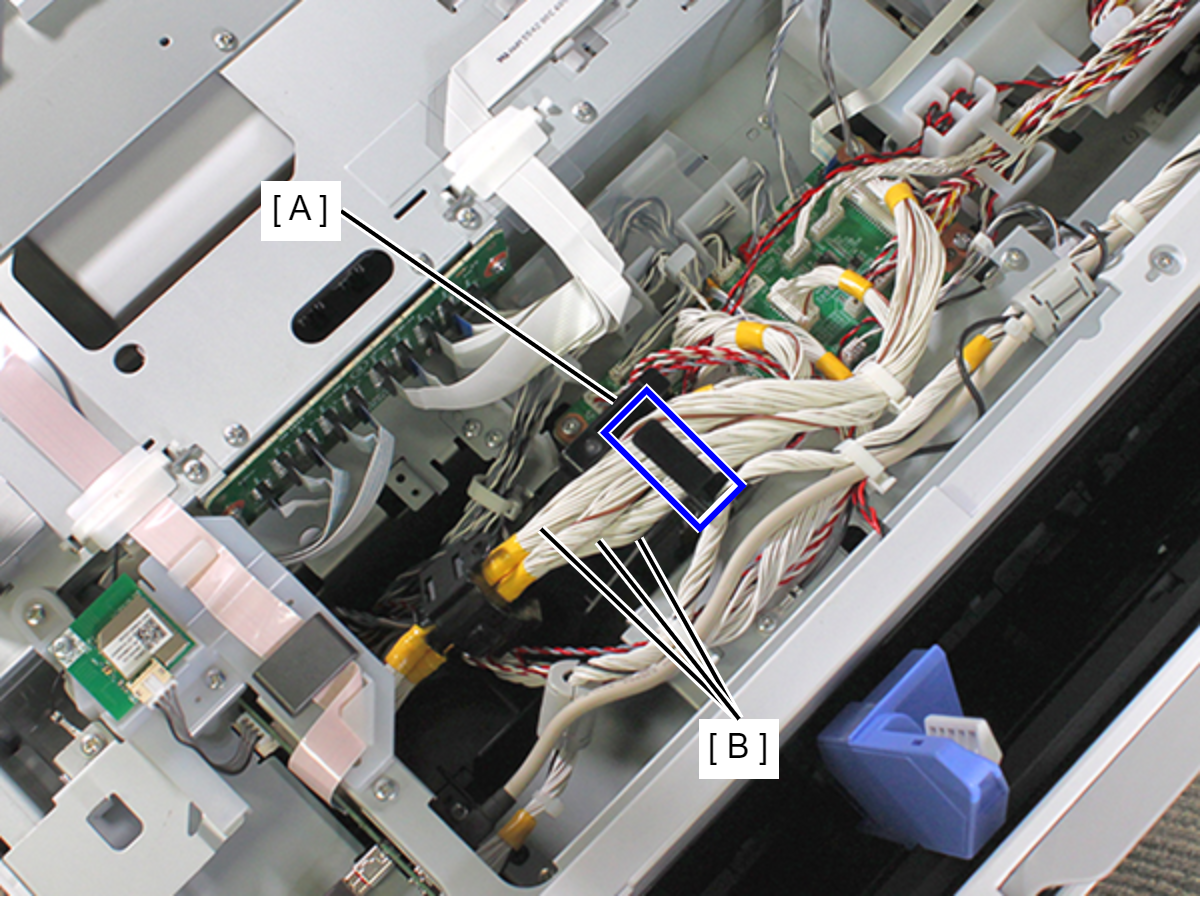
- Remove two screws, and remove the Relay Harness Cover (A).
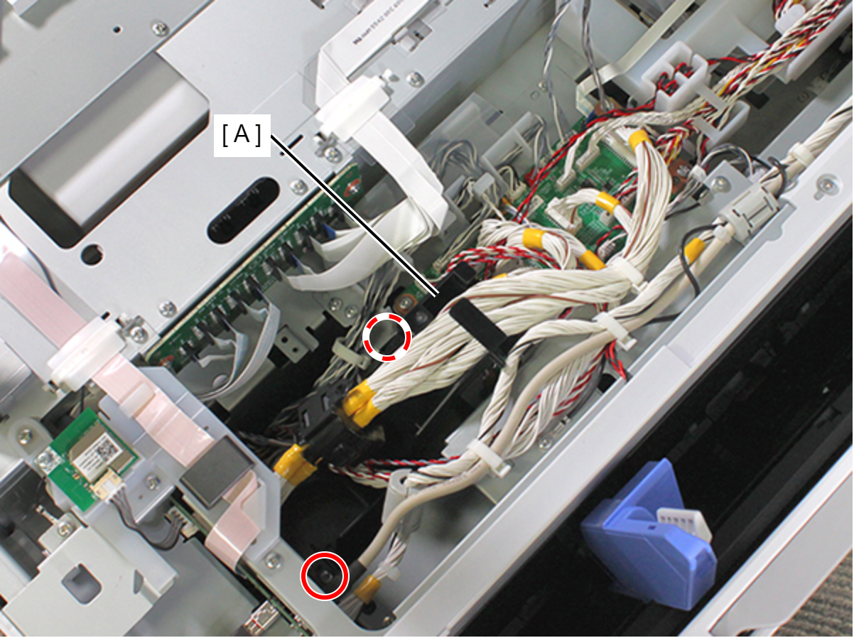
- : C.B.S-TITE-SCREW-3x8-F.ZN-3C
- Disconnect the five relay cables (A) from the PCB Mechanism Relay Board.
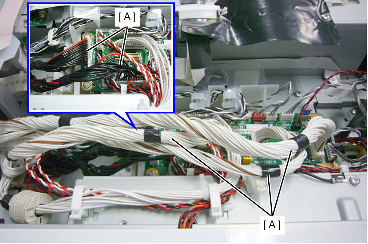
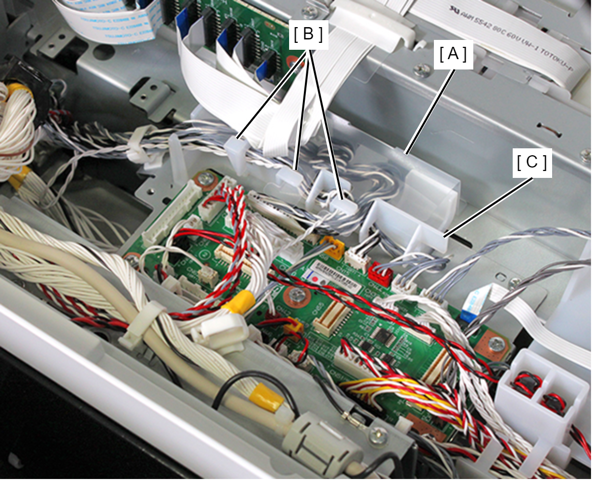
- Release the three hooks (B) of the lumirror (A) covering the cable holder (C) and open the lumirror (A).
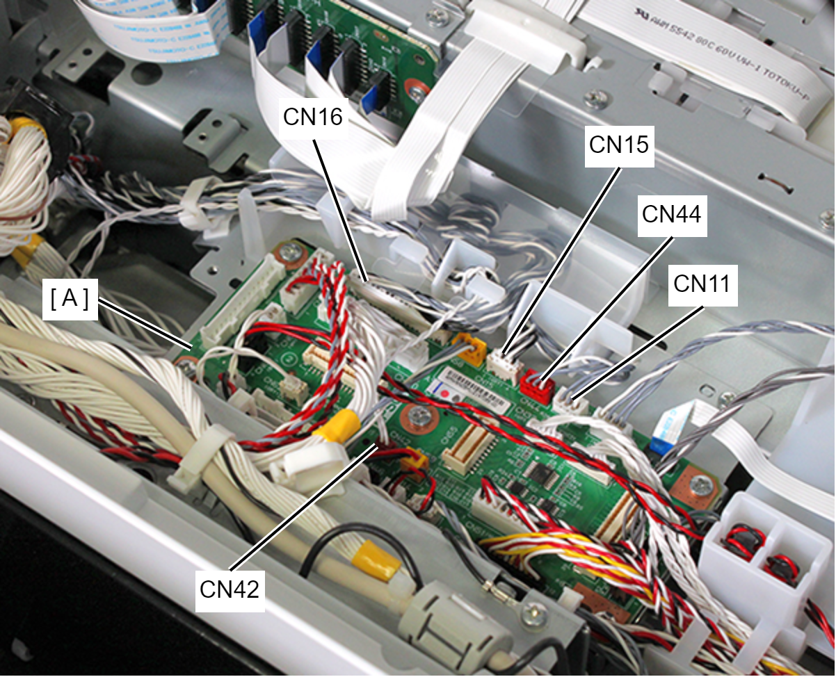
- Remove the cables from the connectors (CN11, CN15, CN16, CN44, CN42) of the PCB Mechanism Relay Board (A).
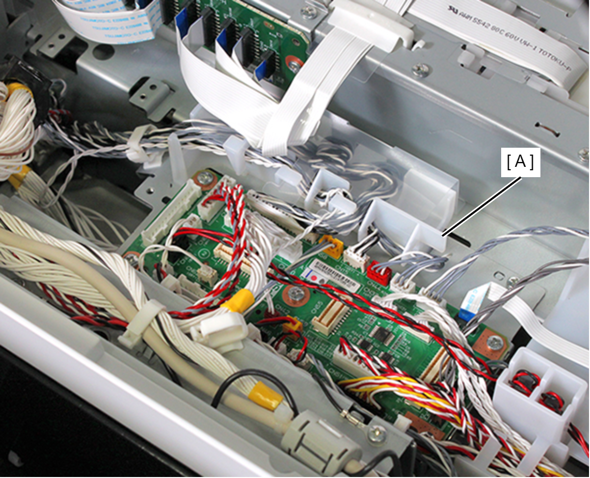
- Release the cables from the Cable Holder (A).
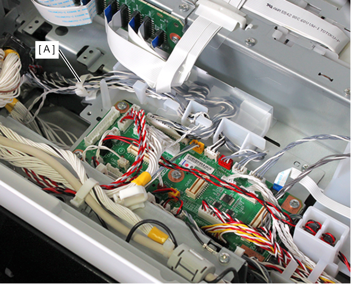
- Release the cable from the clamp (A).
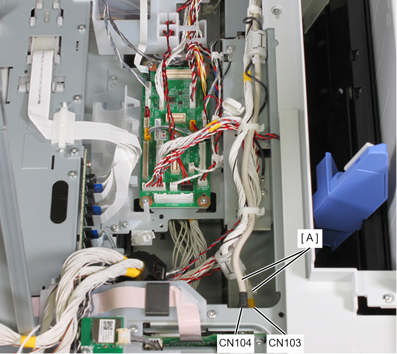
- Remove the ADF/SCN cable (A) from the connectors (CN103 (with hooks), CN104) of the Main Board.
- Remove the screw, then remove the SCN ground cable (A).
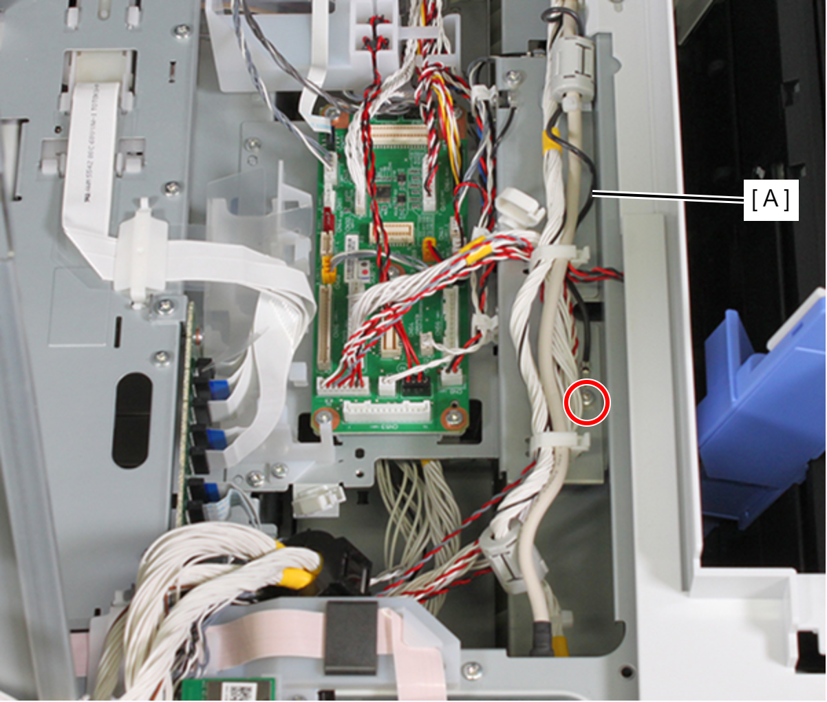
- : C.B.S-TITE-SCREW-3x8-F.ZN-3C
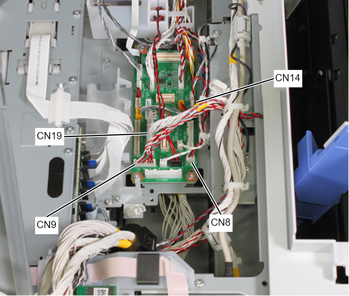
- Remove the cables from the connectors (CN8, CN9, CN14, CN19 (with hooks)) of the PCB Mechanism Relay Board.
- Release the cable from the two clamps (A).
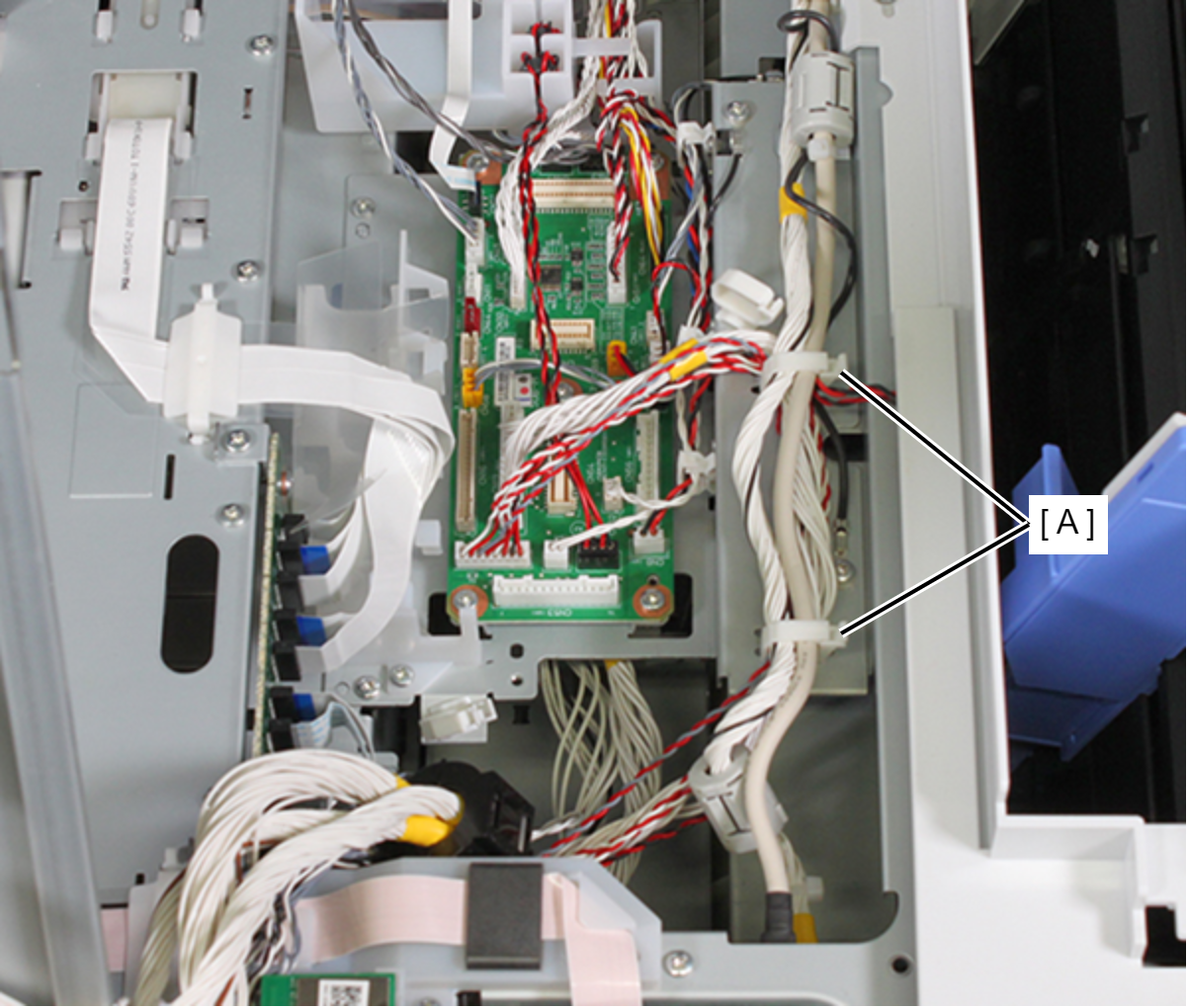
- Release the cable from the three clamps (A).
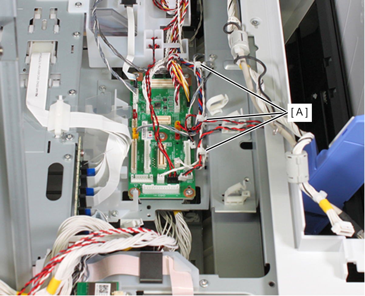
- Remove the cable/FFC from all connectors of the PCB Mechanism Relay Board (A).
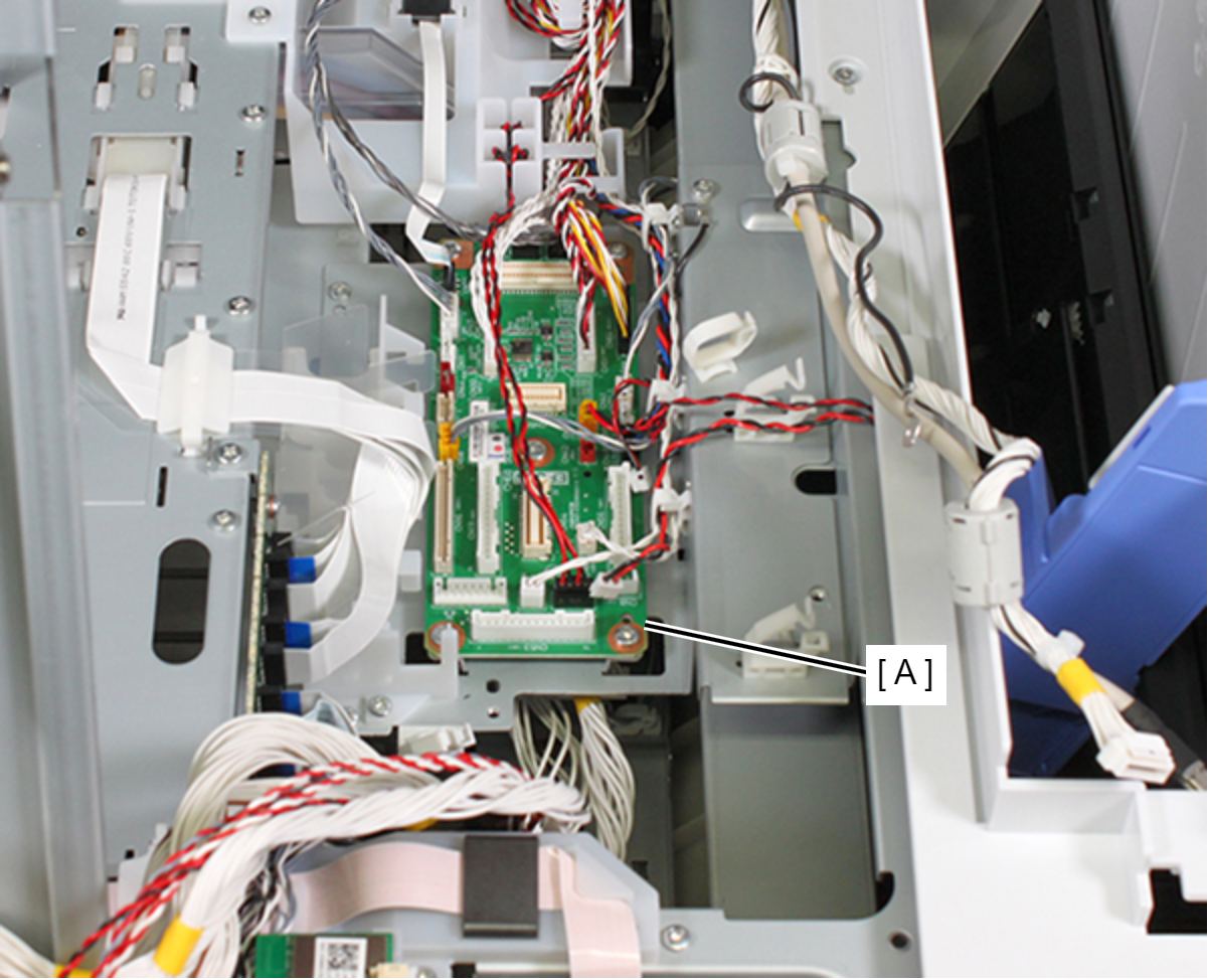
- Remove the screw, then remove the grounding wire (A).
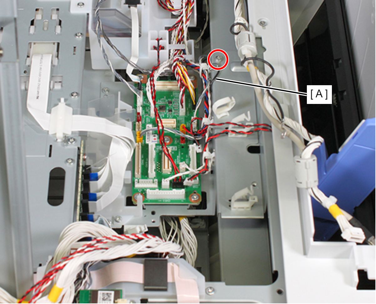
- : C.B.S-TITE-SCREW-3x8-F.ZN-3C
- Remove the three screws, then remove the PCB Mechanism Relay Board (with Mounting Plate) (A).
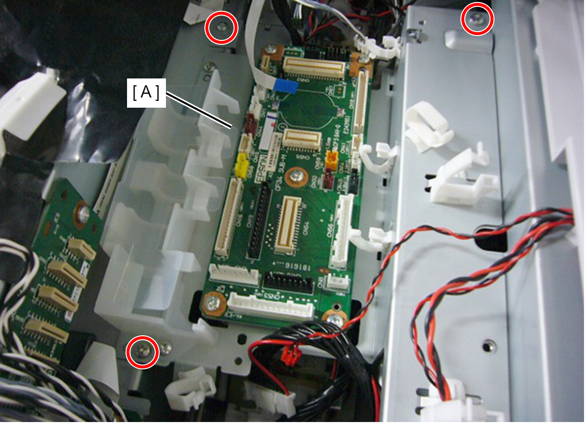
- : C.B.S-TITE-SCREW-3x8-F.ZN-3C
- Release the cables (B) from the Cable Holder (A).
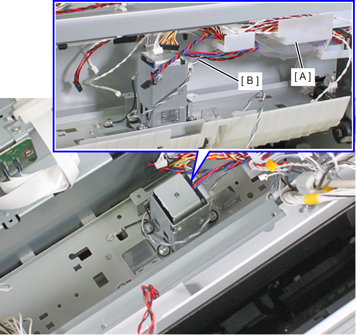
- Release the cable (B) from the clamp (A).
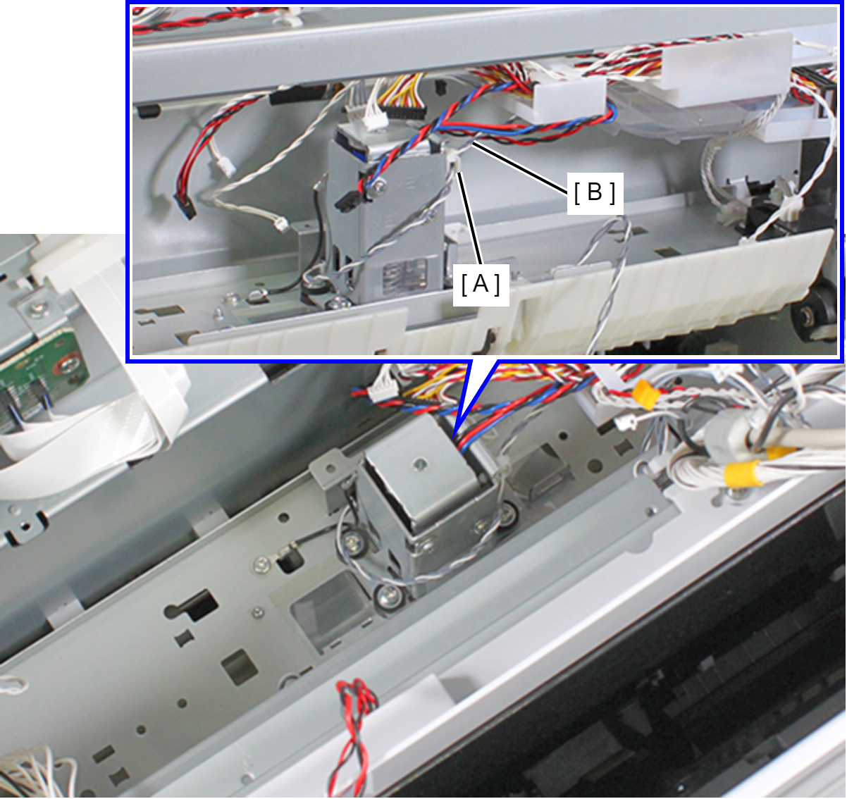
- Remove one screw, then release the Grounding Wire (A).
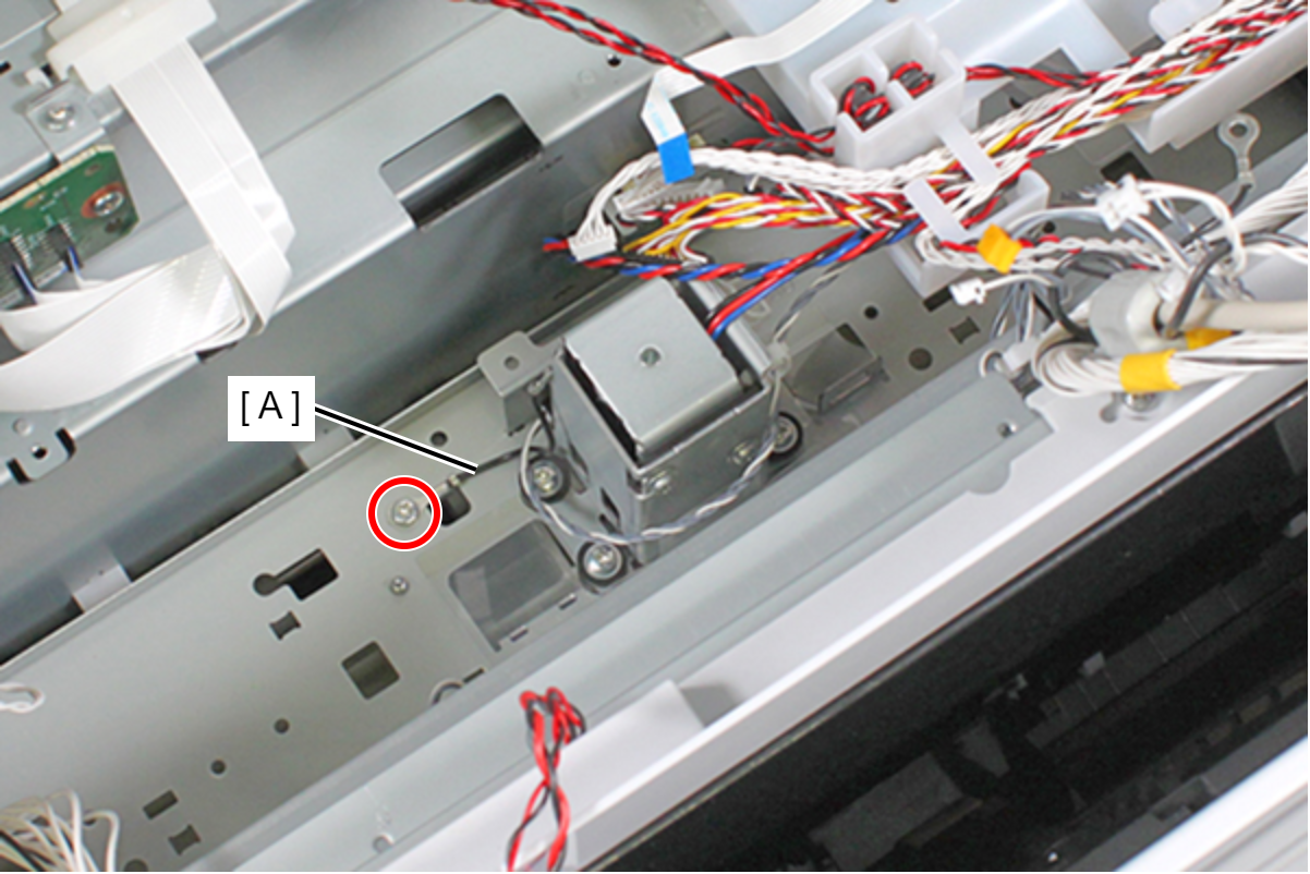
 : C.B.S-TITE-SCREW-3x8-F.ZN-3C
- Remove the three screws and remove the Intermediate Release Solenoid (A).
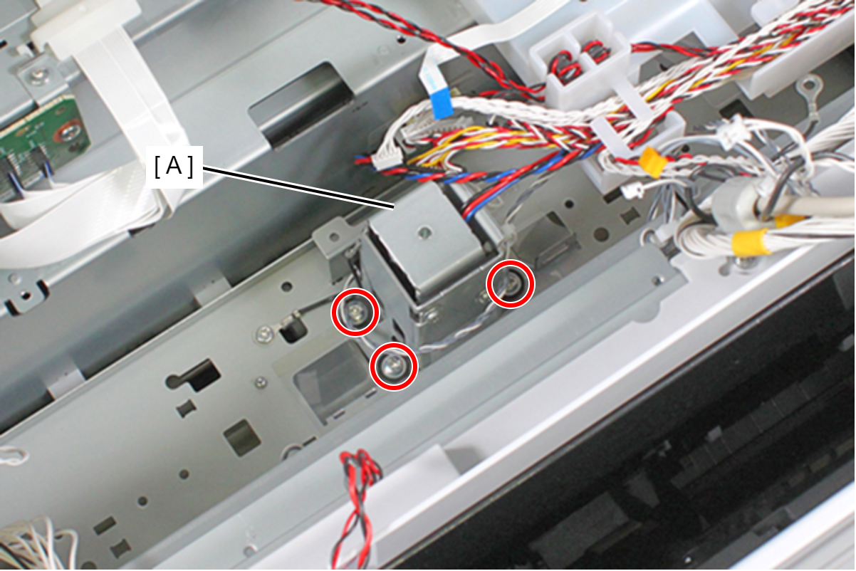
- : C.B.S-TITE.P4.SCREW-3x12-F.ZN-3C
 Assembly / 組み立て
Insert the plunger (A) into the hole on the Intermediate Release Solenoid (B).
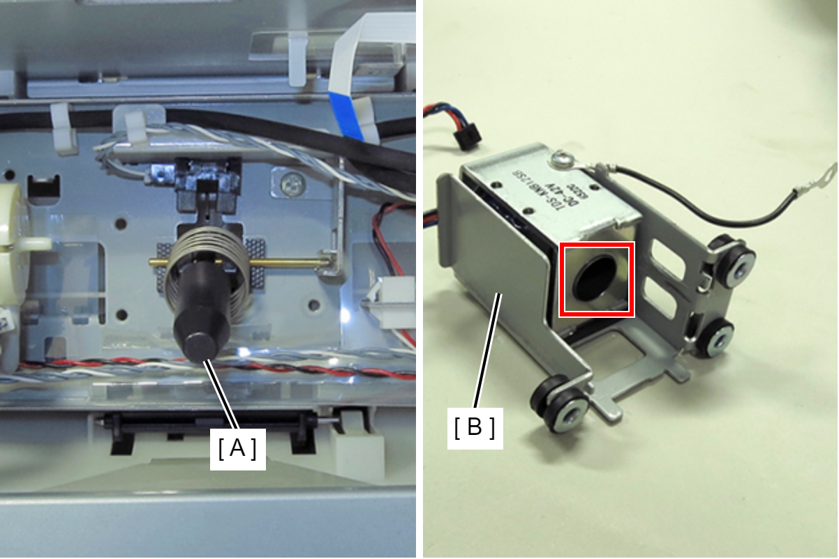 Check Point / チェックポイント
When replacing the Intermediate Release Solenoid (A), replace the plunger (B) too simultaneously.
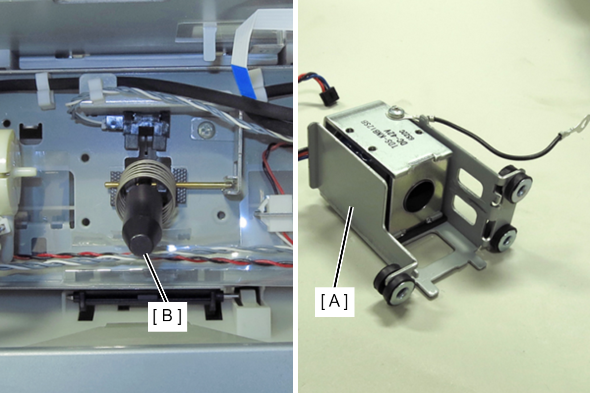
| Adjustment / 調整 |
After replacing this part, you need to run the menu from the service support mode. (If you ran the Before-replacement menu before replacing the part, it will start automatically when you turn the power on.) |