
CR Ferrite Core Holder
- Remove one screw.
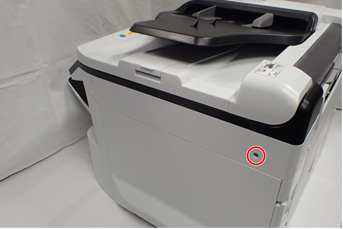
 : C.B.S-TITE-SCREW-3x8-F.ZN-3C
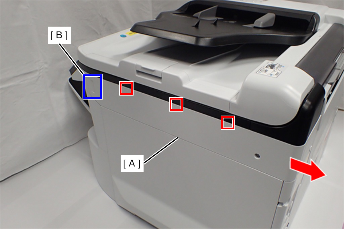
- Slide the Right SC Cover (A) while pushing the dent (B) of Right SC Cover, and release the three tabs. Remove the Right SC Cover (A).
- Remove one screw.
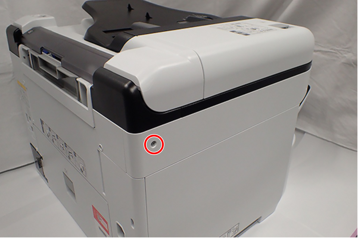
- : C.B.S-TITE-SCREW-3x8-F.ZN-3C
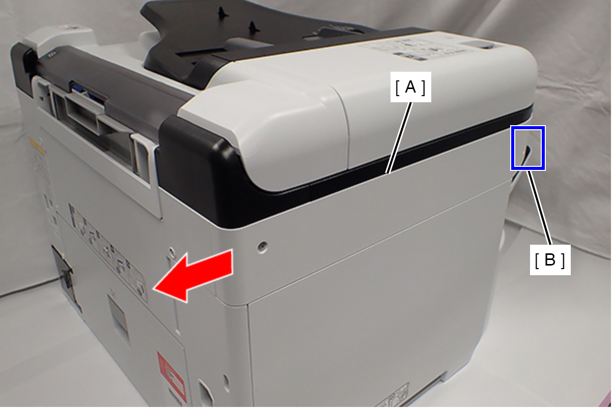
- Slide the Left SC Cover (A) while pushing the dent (B) of Left SC Cover, and remove it.
- Remove one screw, and remove the Lower SC Reinforcing Plate (A).
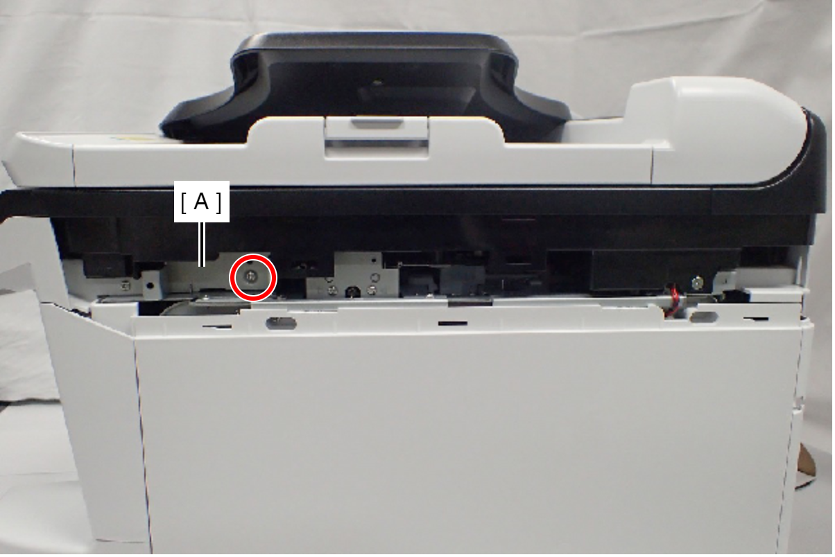
- : C.B.S-TITE-SCREW-3x8-F.ZN-3C
- Reattach the Lower SC Reinforcing Plate (A) in its portrait orientation, then secure it with the screw.
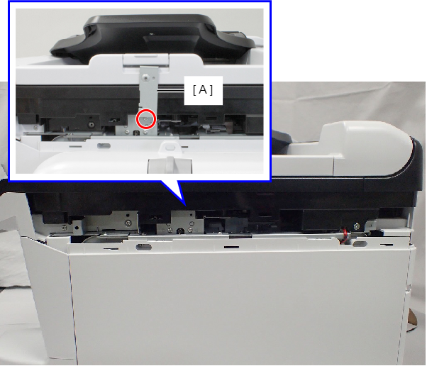
- : C.B.S-TITE-SCREW-3x8-F.ZN-3C
- Remove the screw.
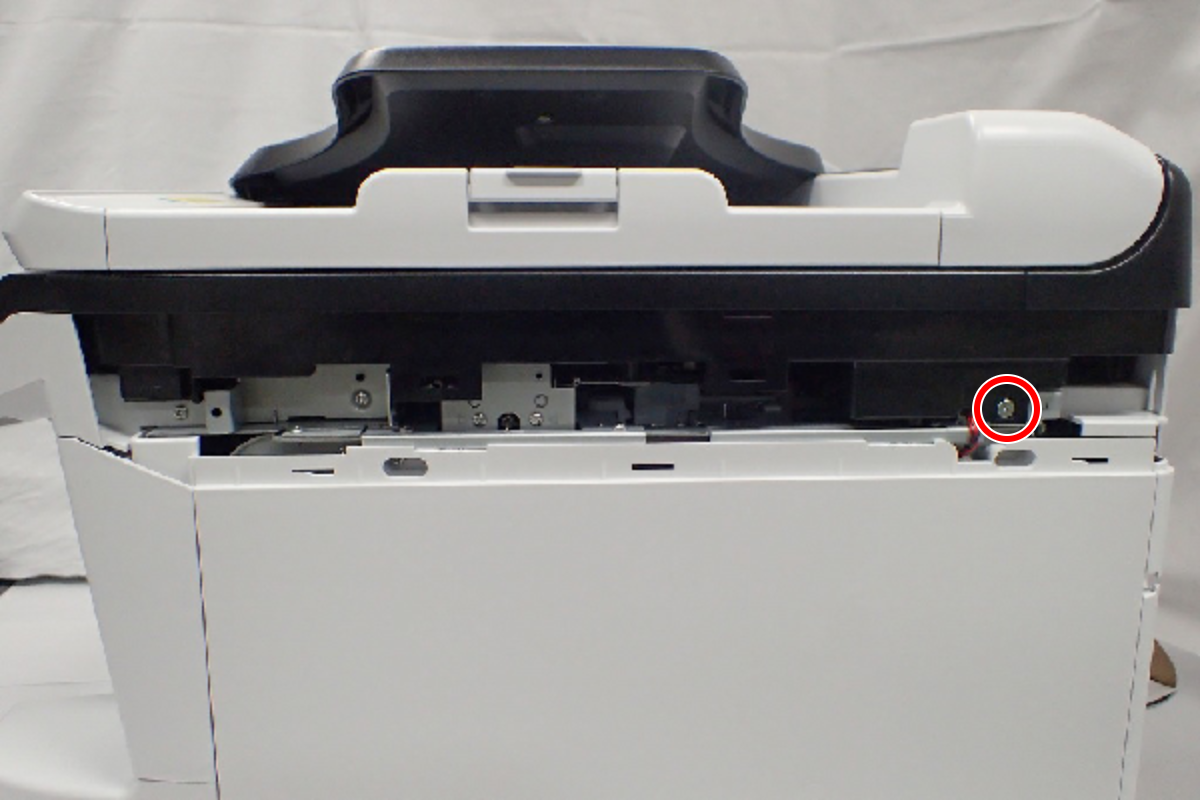
- : C.SHOULDER S-TITE,3X5
- Open the ADF/SCN Unit (A).
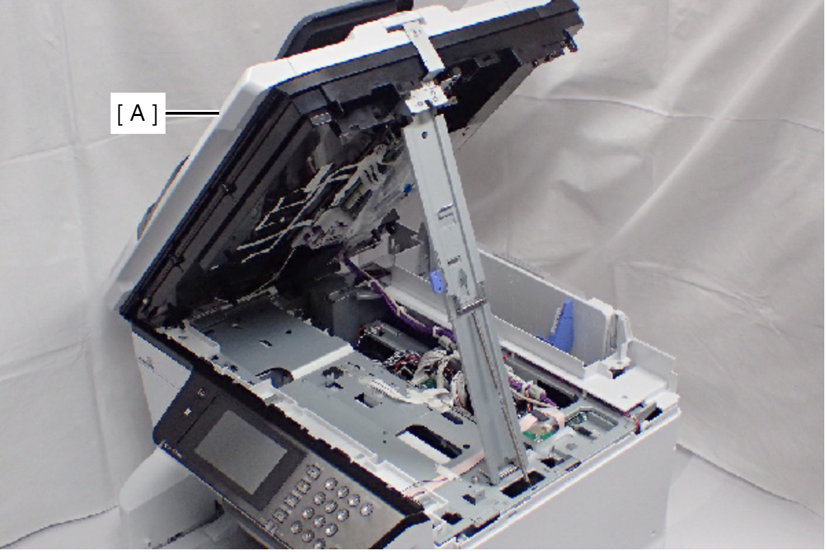
- Open the ADF/SCN Unit (A) and extend the support stand (B) as far as it goes, then support the ADF/SCN Unit with the support stand.
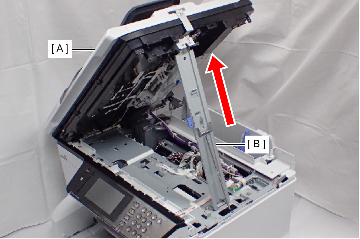
 Caution / 注意
Make sure that the support stand (A) is fixed with the two hooks, and the two triangle marks (B) face to each other.
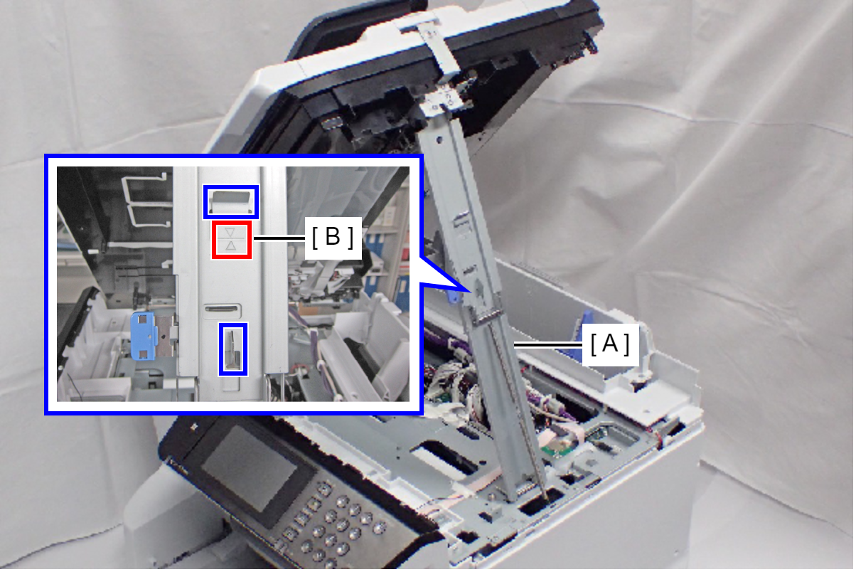
 Check Point / チェックポイント
When closing the ADF/SCN Unit (A), press the switch (C) on the ADF/SCN support stand (B) and hold up the ADF/SCN Unit to disengage the two hooks, then fold the ADF/SCN support stand.
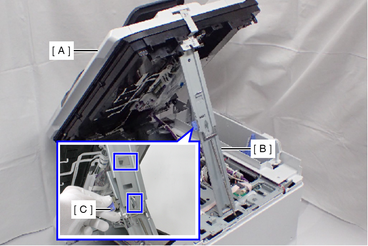
- Open the Duplex Print Cover (A).
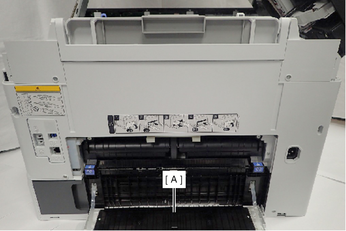
- Remove the seven screws.
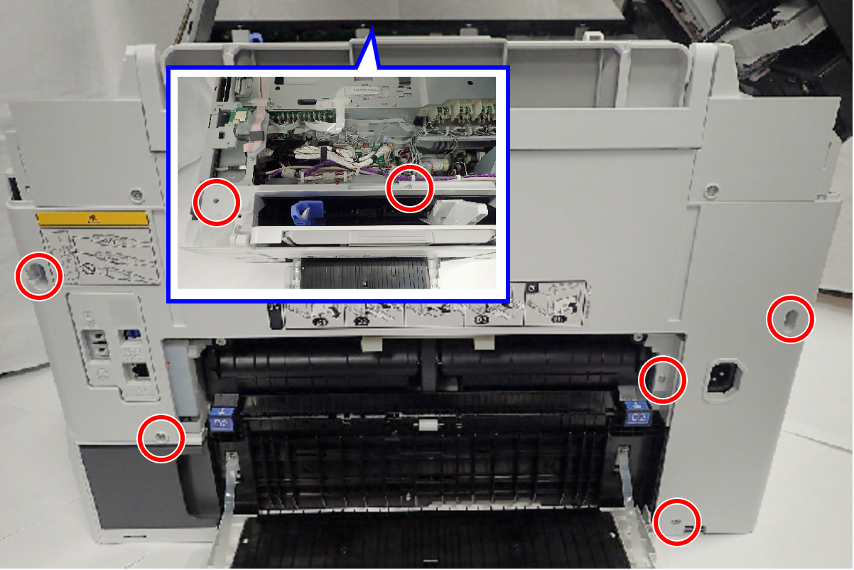
 : C.B.S-TITE-SCREW-3x8-F.ZN-3C
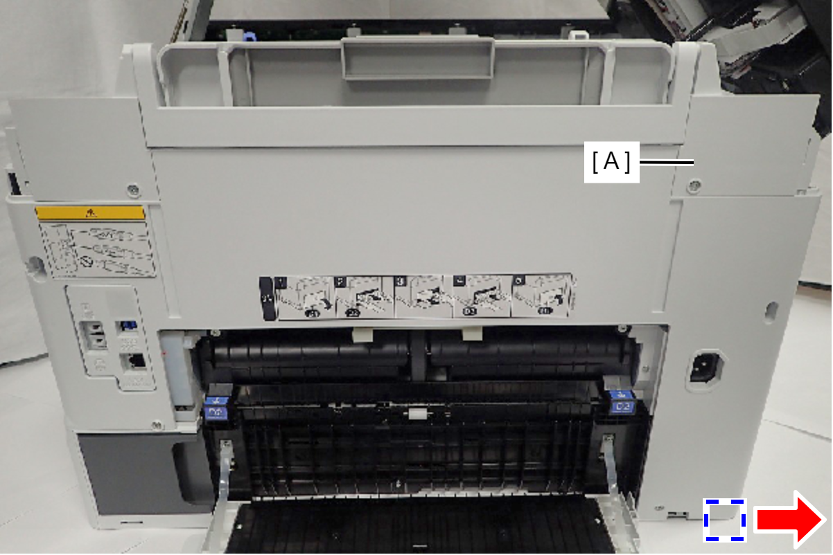
- Press the Rear Housing Assy (A) in the direction of the arrow, then release the hook.
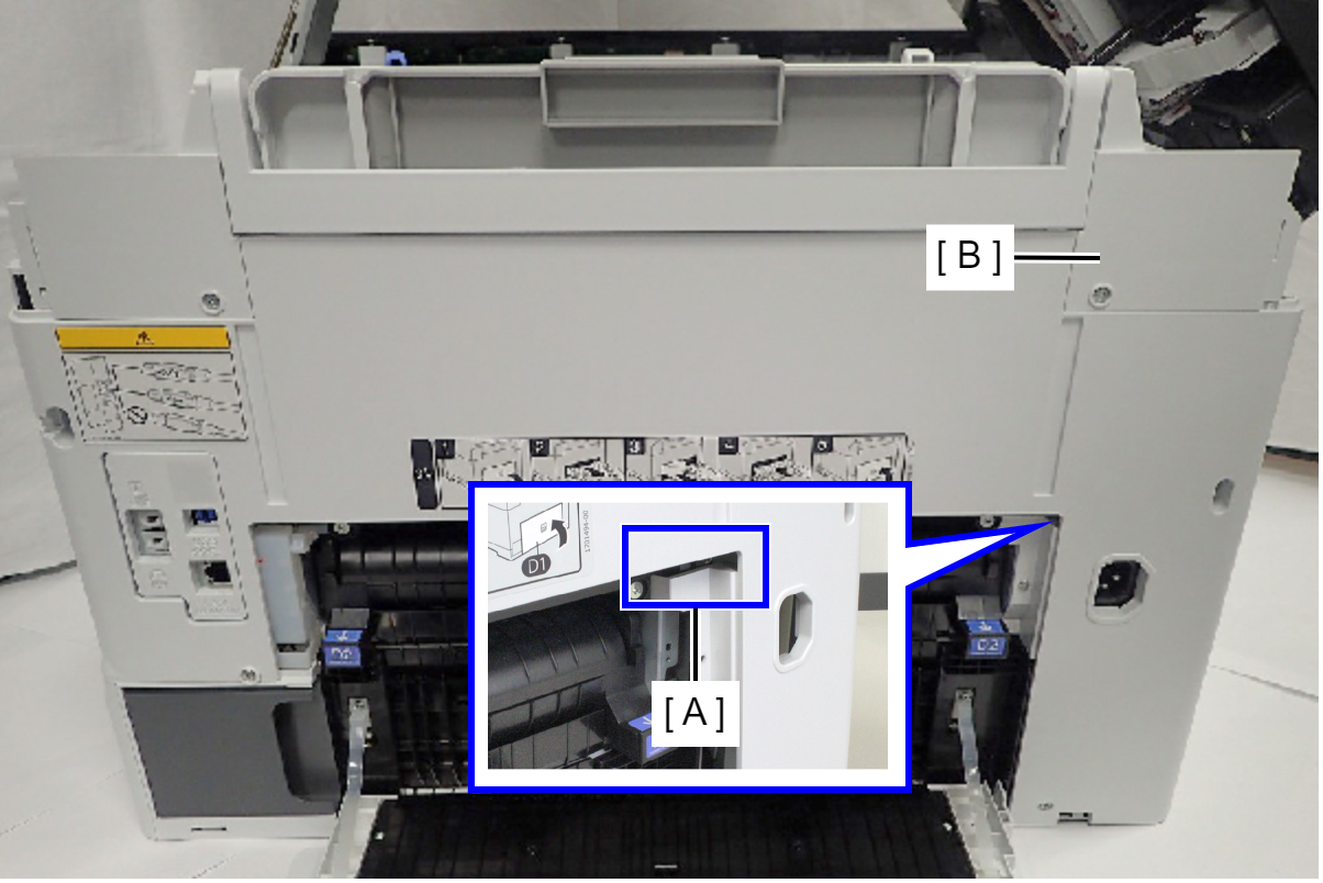
- Remove the Rear Housing Assy (B) while releasing the place interfering with the Rear ASF Unit (A).
- Remove the two screws, then remove the PS Harness Holder (A).
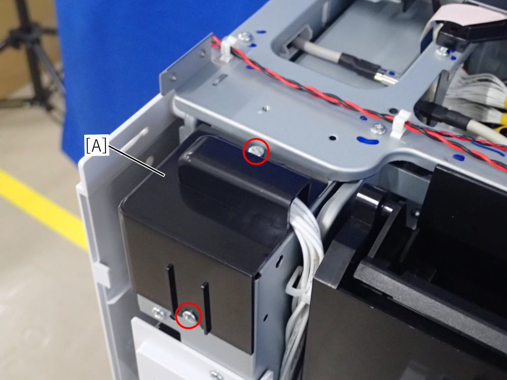
- : C.B.S-TITE-SCREW-3x8-F.ZN-3C
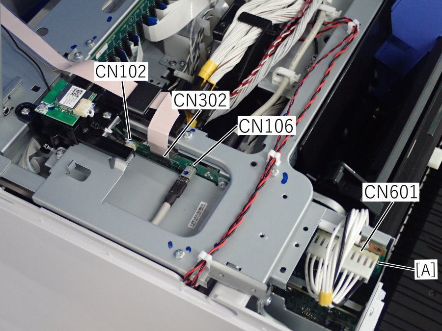
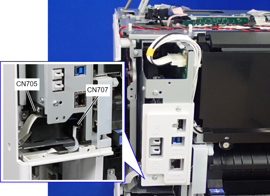
- Disconnect the following cables and FFCs from the Main Board (A).
Panel FFC (CN302)
USB Host Cable (CN106)
Wi-Fi Module Cable (CN102)
Power Supply Unit Cable (CN601) (with hook)
CRCM FFC (CN705)
MB CSIC FFC (CN707)
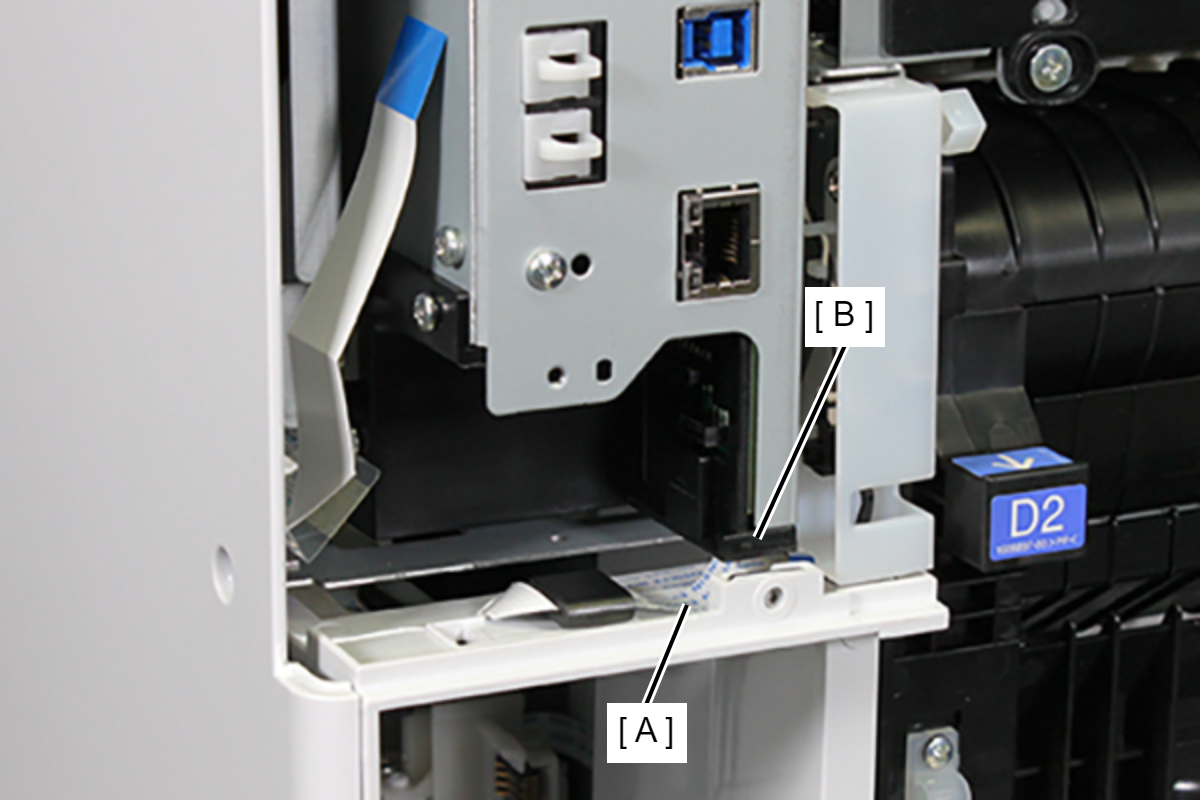
- Put the MB CSIC FFC (A) under the holder (B).
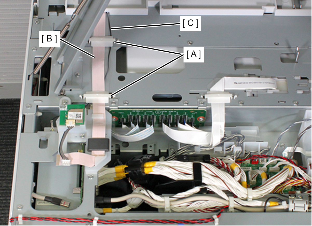
- Remove the two FFC clamps (A), then release the panel FFC (B) and grounding wire (C).
- Remove one screw, then release the Grounding Wire (A).
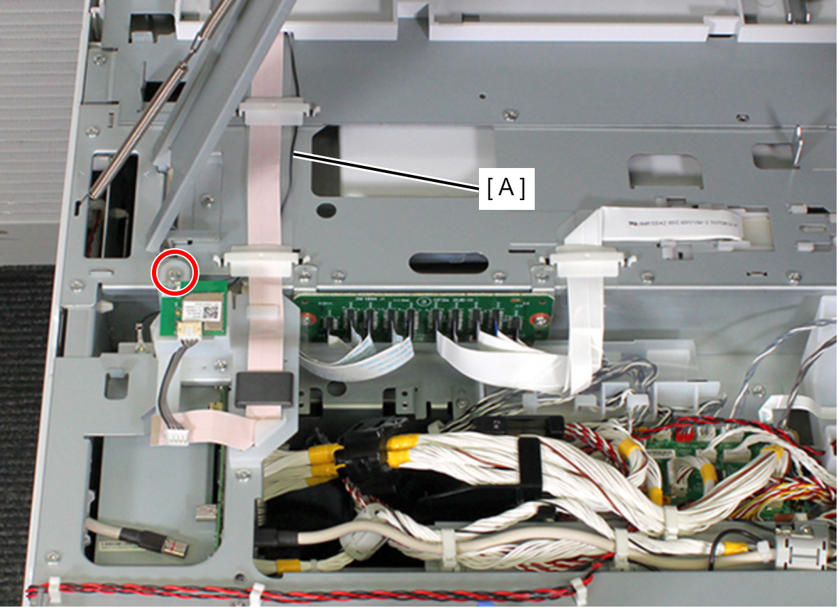
- : C.B.S-TITE-SCREW-3x8-F.ZN-3C
- Remove the Panel FFC (B) from the ferrite core (A).
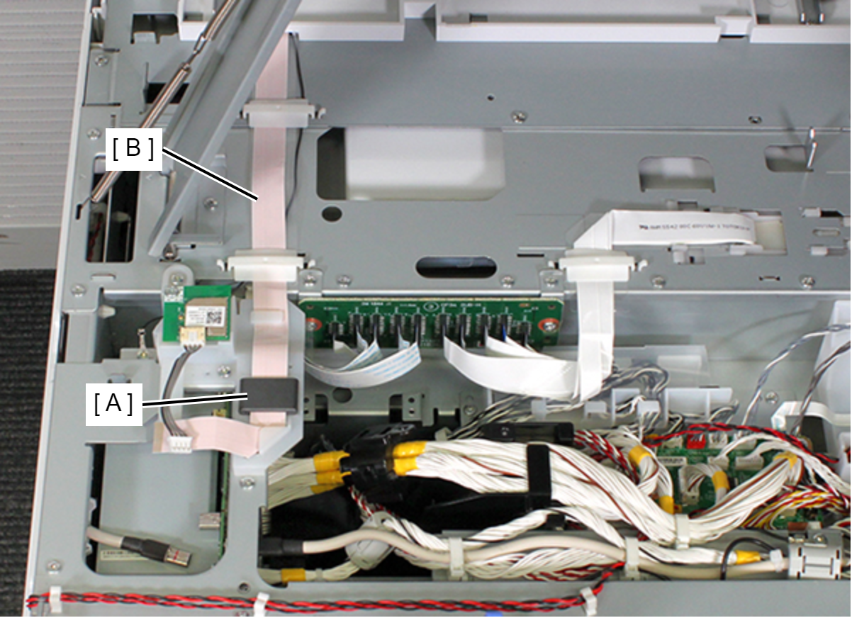
- Remove two screws, and remove the Panel Cable Guide (A).
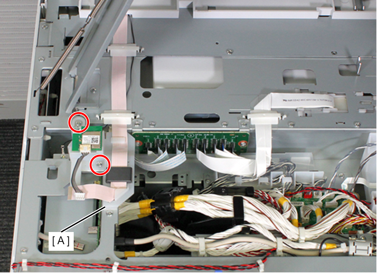
- : C.B.S-TITE-SCREW-3x8-F.ZN-3C
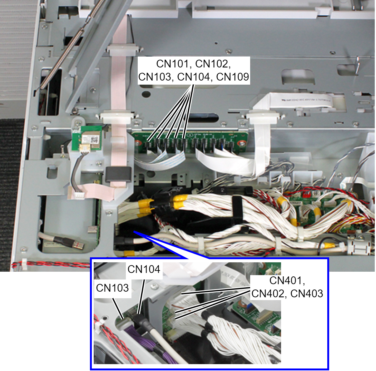
Disconnect the following cables and FFCs.
Head Relay FFC (CN101, CN102, CN103, CN104, CN109)
Relay Cables (CN401, CN402, CN403) (with hook)
ADF/SCN Cable (USB) (CN104)
ADF/SCN Cable (CN103) (With hook)
- Remove the FFC clamp (A), then release the head relay FFC.
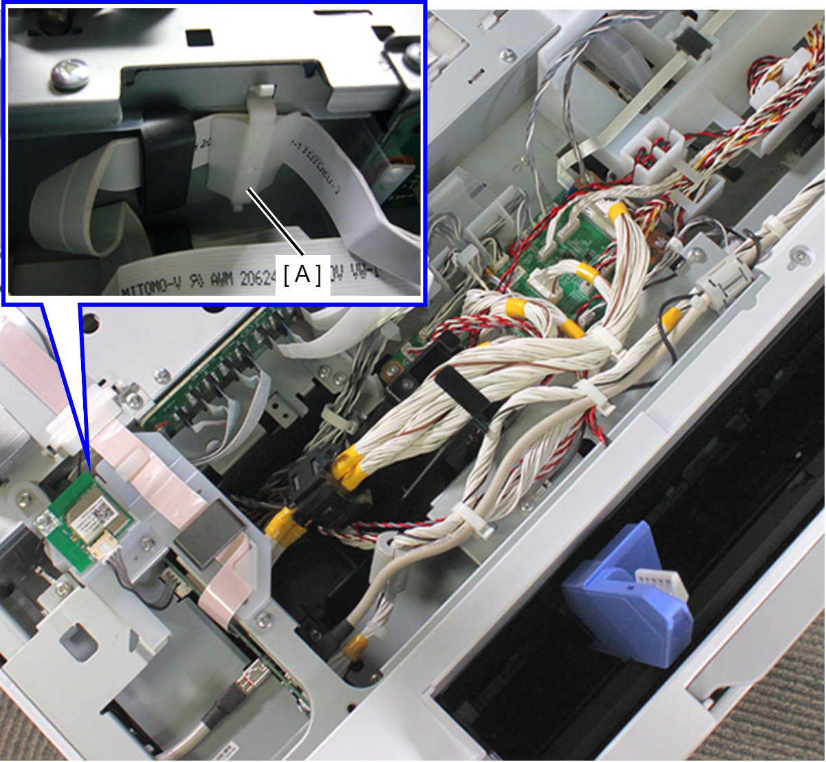
- Release the ADF/SCN cable (A) from the hooks of the Relay Harness Cover (B).
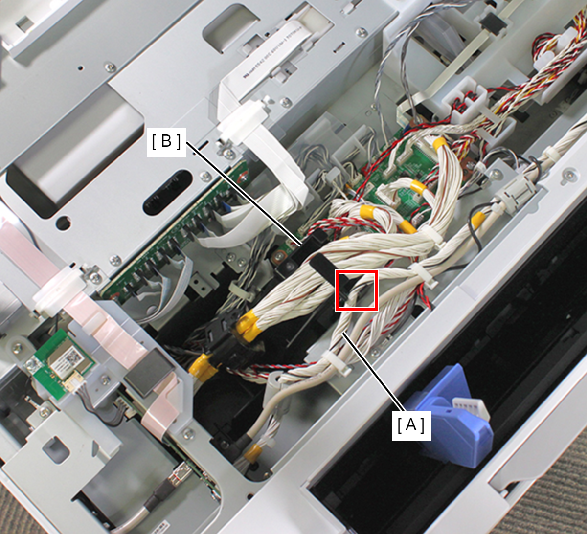
- Release the two relay cables (B) from the clamp (A).
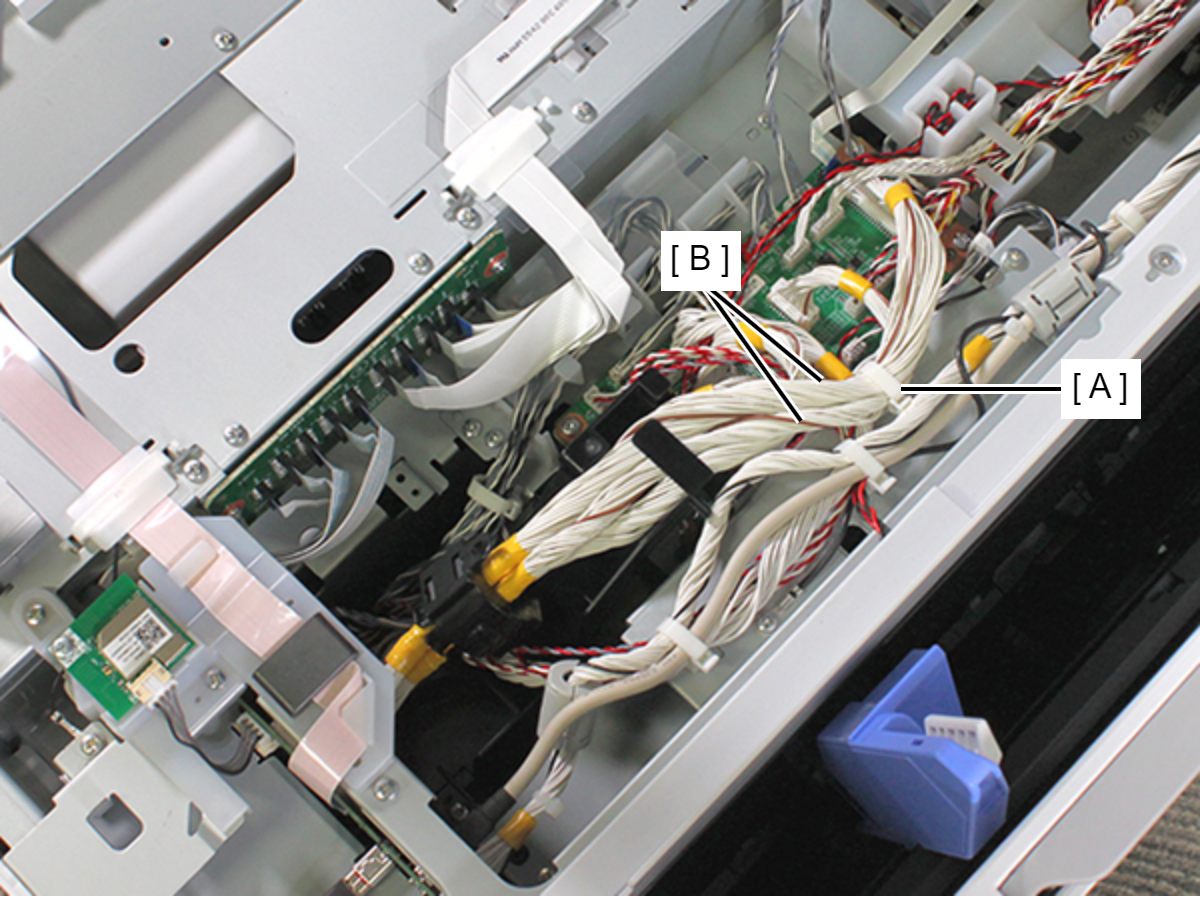
- Release the three relay cables (B) from the hooks of the Relay Harness Cover (A).
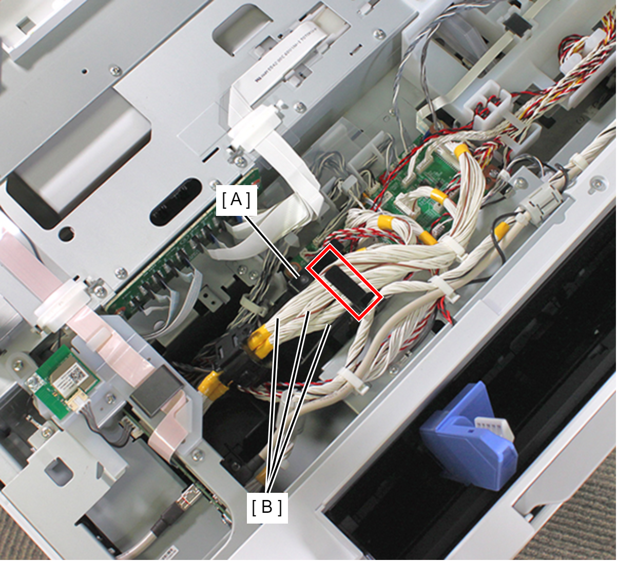
- Remove two screws, and remove the Relay Harness Cover (A).
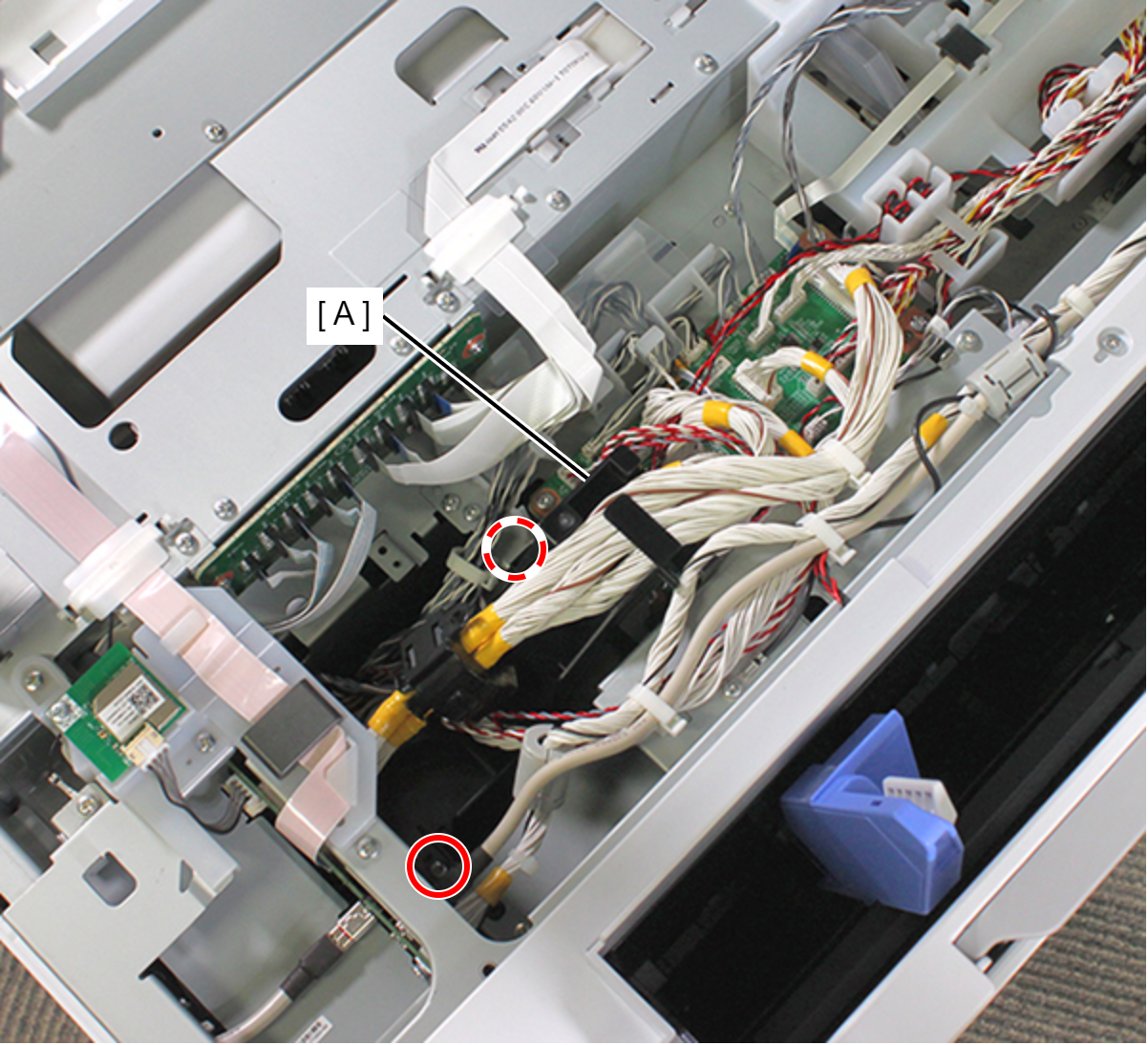
- : C.B.S-TITE-SCREW-3x8-F.ZN-3C
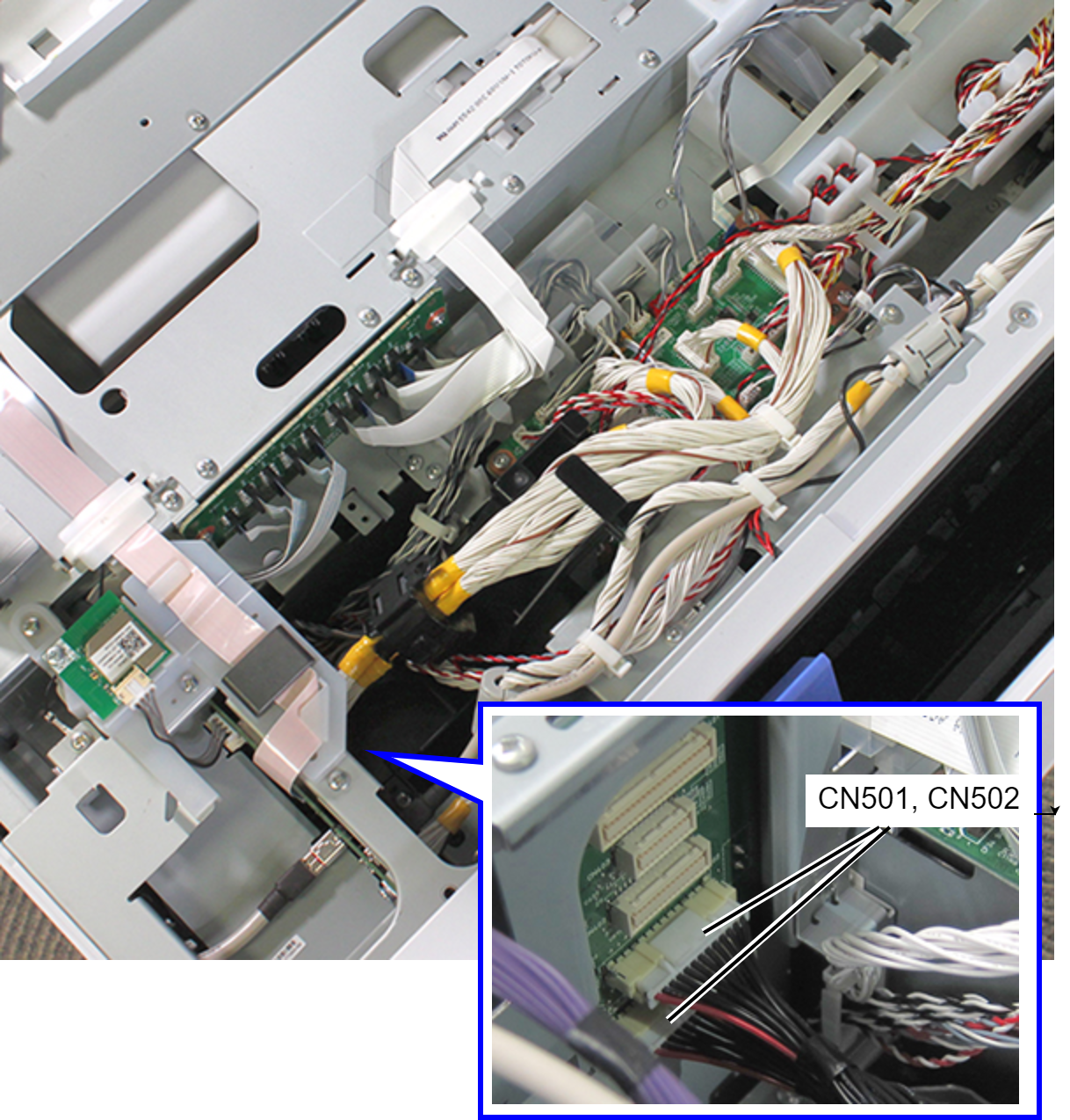
- Remove the two cables (with hooks) from the connectors (CN501, CN502) of the Main Board.
- Remove the two screws, and remove the Main Board Unit (A) to direction of arrow.
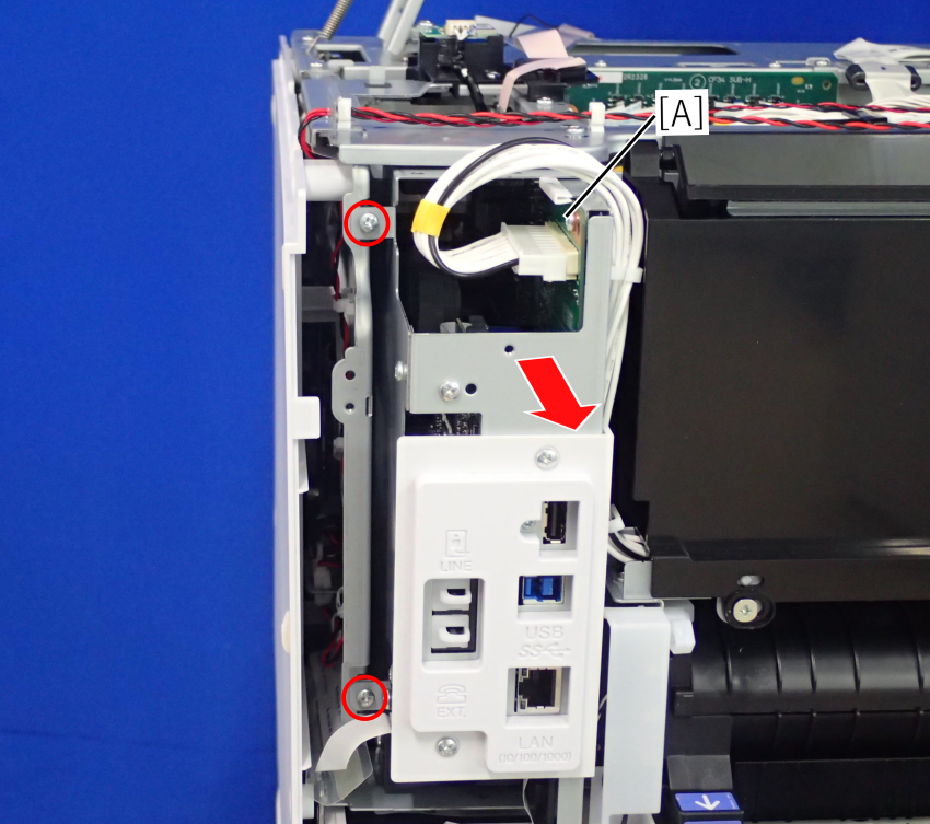
- : C.B.S-TITE-SCREW-3x8-F.ZN-3C
 Assembly / 組み立て
Connect the Head Relay FFC by the following procedure.
- Remove the FFC Clamp (A).
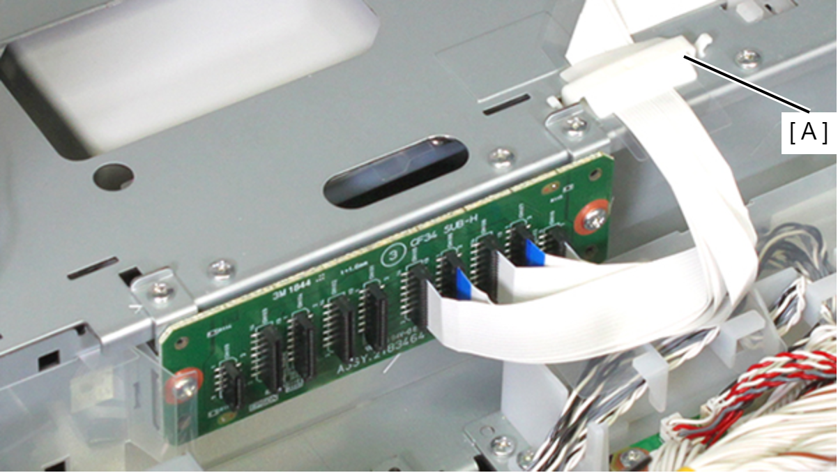
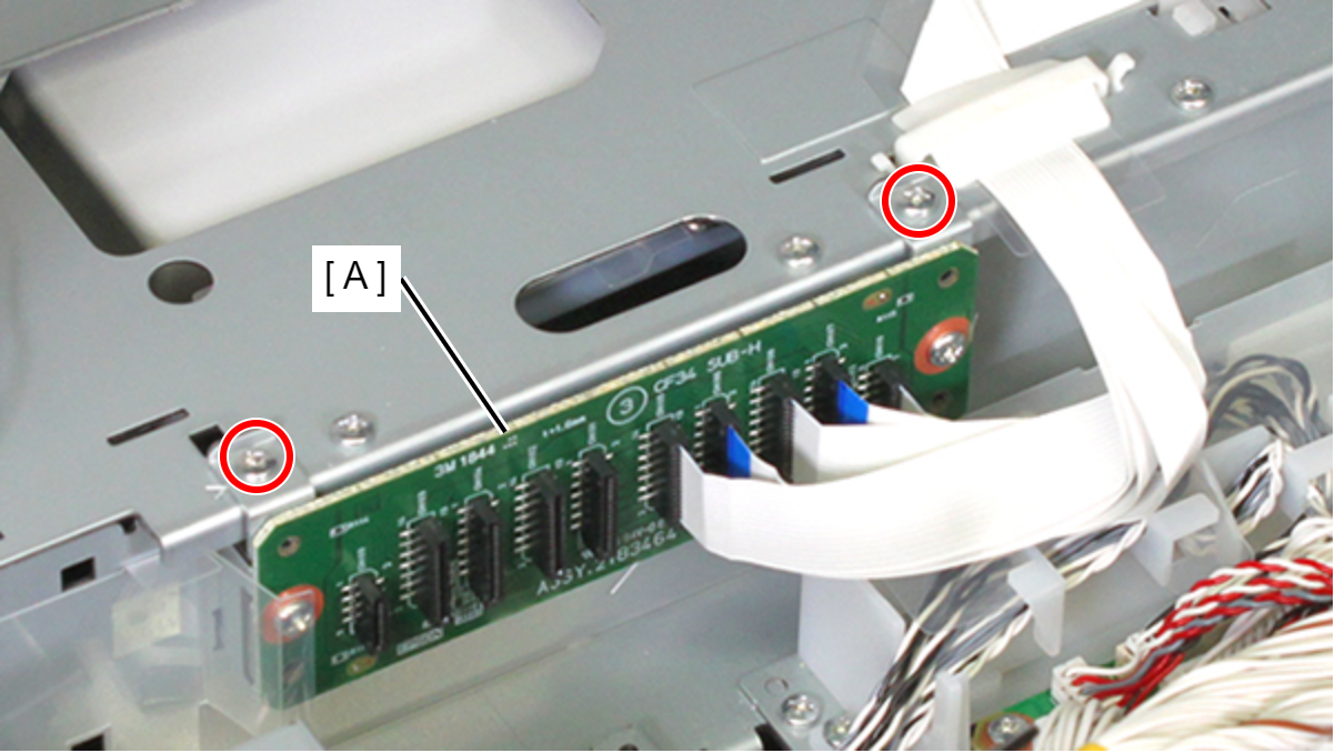
- Remove the two screws, then remove the Relay Board Assy (A).
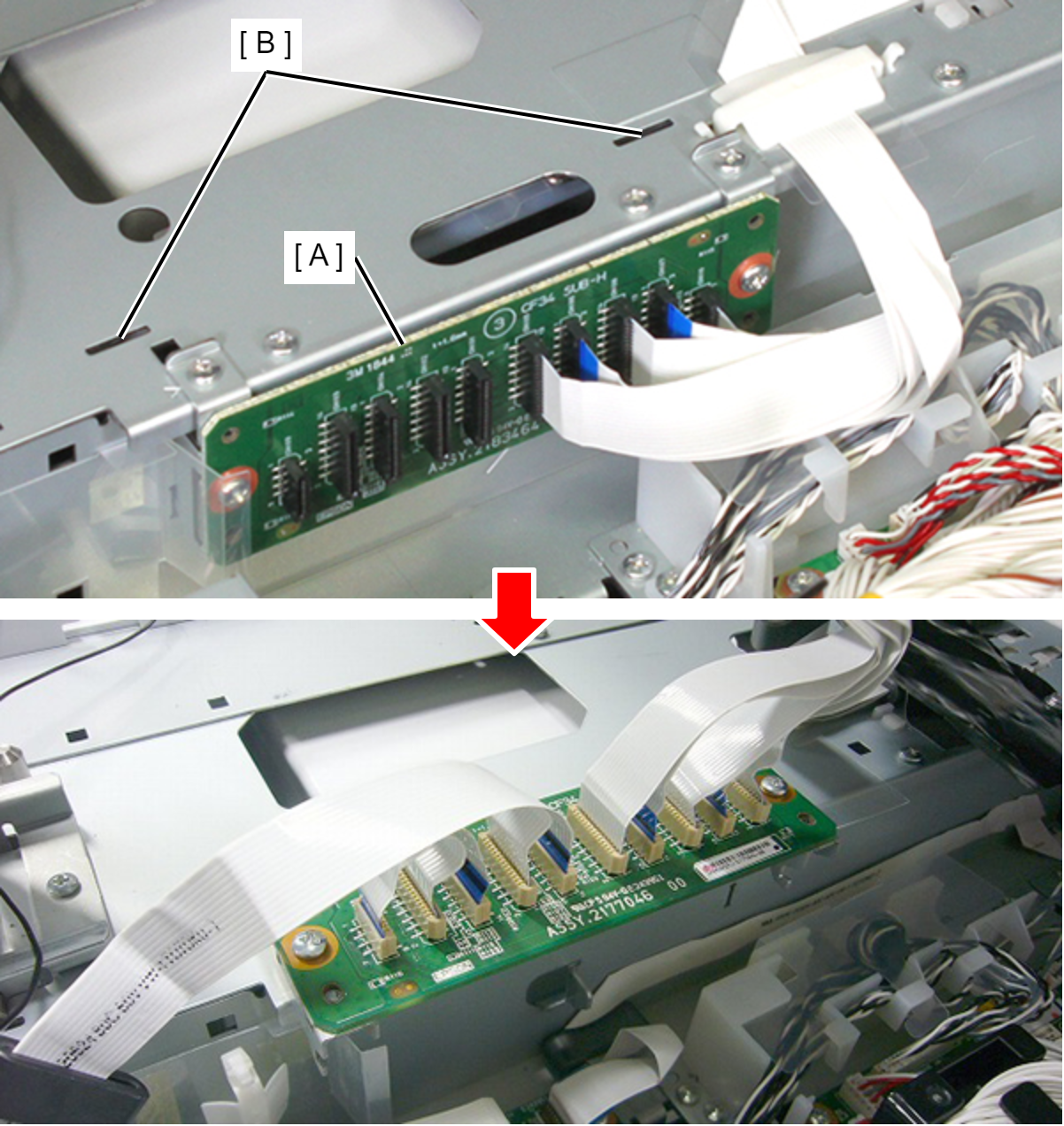
- Insert the two tabs of the Relay Board Assy (A) frame into the holes (B) on the main frame to temporarily secure the Relay Board Assy (A) with the assy facing upward.
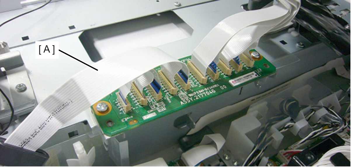
- Connect the head relay FFC. (Take care not to connect obliquely.)
- Remove the seven screws, then remove the Shield Plate MB Upper Assy (A).
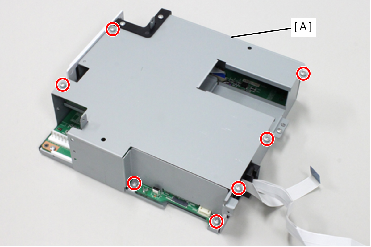
- : C.B.S-TITE-SCREW-3x8-F.ZN-3C
- Disconnect the FFCs from the connectors (CN404, CN701, CN702, CN704, CN705).
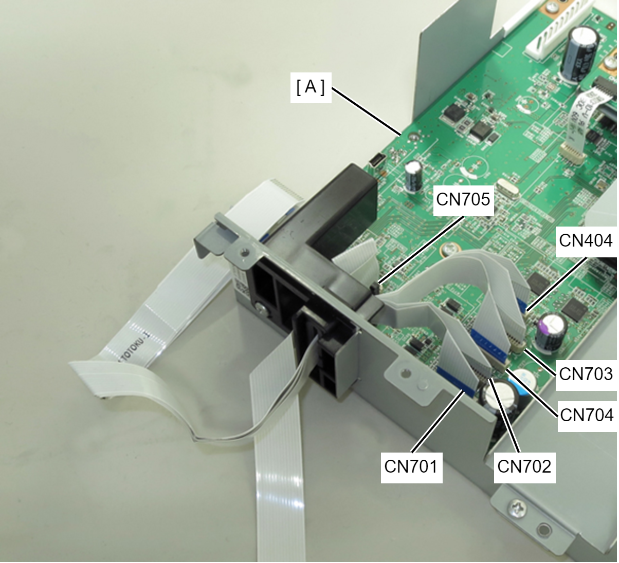
- Remove the screw, then remove the CR Ferrite Core Holder (A).
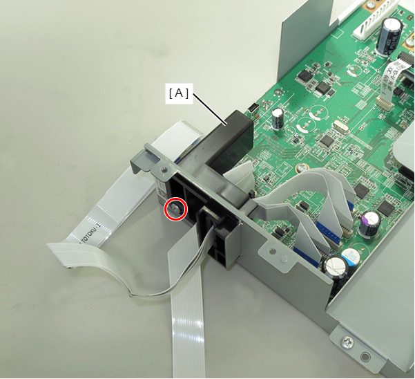
-
- : C.B.S-TITE-SCREW-3x8-F.ZN-3C