
Periodic maintenance procedure
Perform the periodic maintenance operation according to the following procedure.
- Start the Printer by Service Support Mode.(Starting Service Support Mode)
- Select ”04 Maintenance” from Service Support Mode.
- Select ”410 Regular Maintenance”.
- Select ”41001 Before performed”.
- Remove one screw.
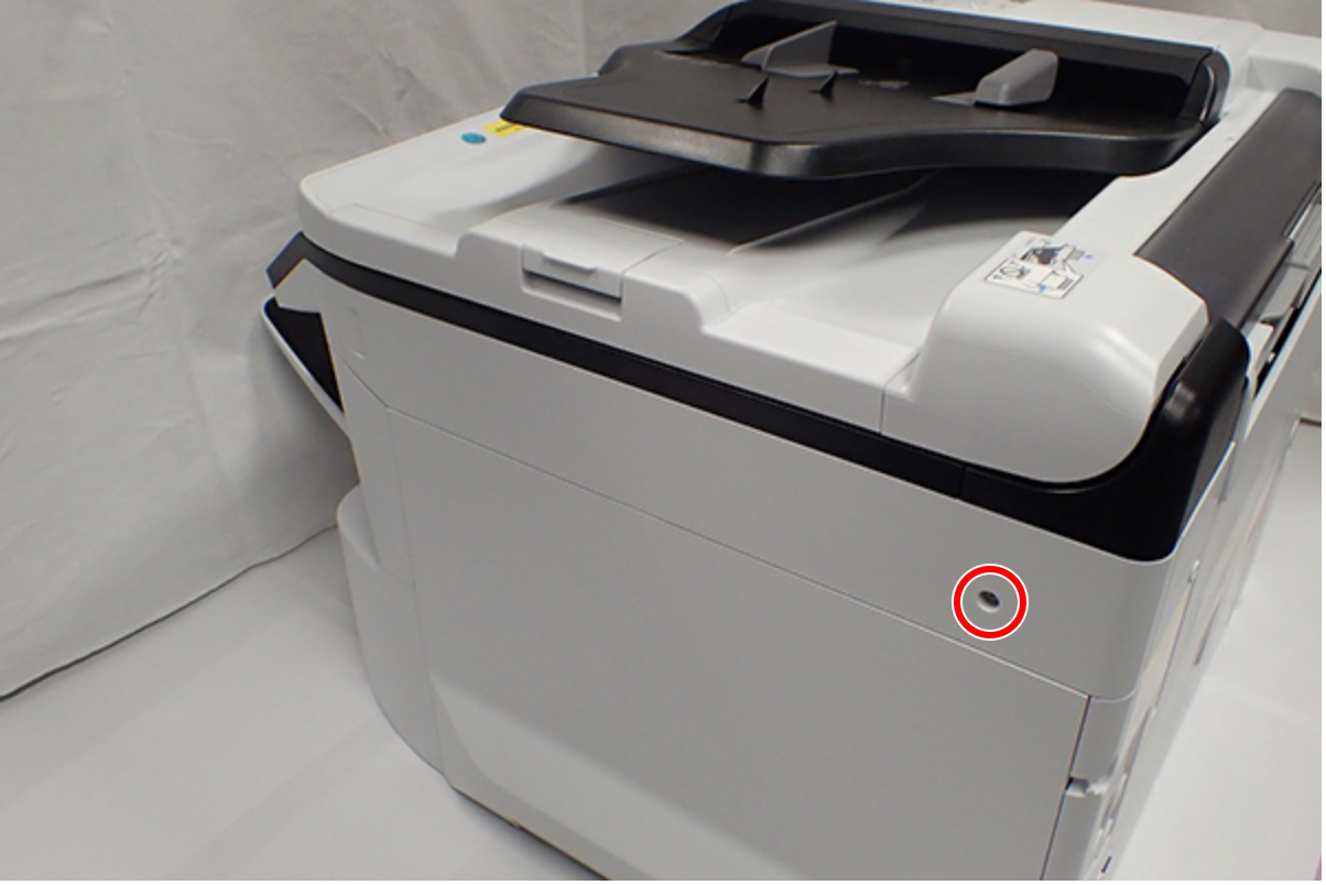
 : C.B.S-TITE-SCREW-3x8-F.ZN-3C
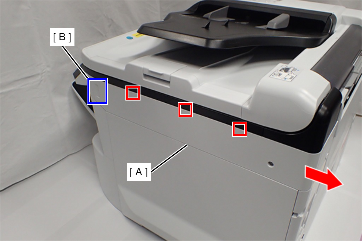
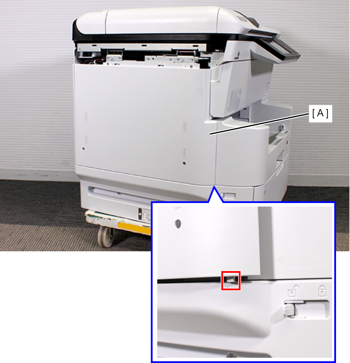
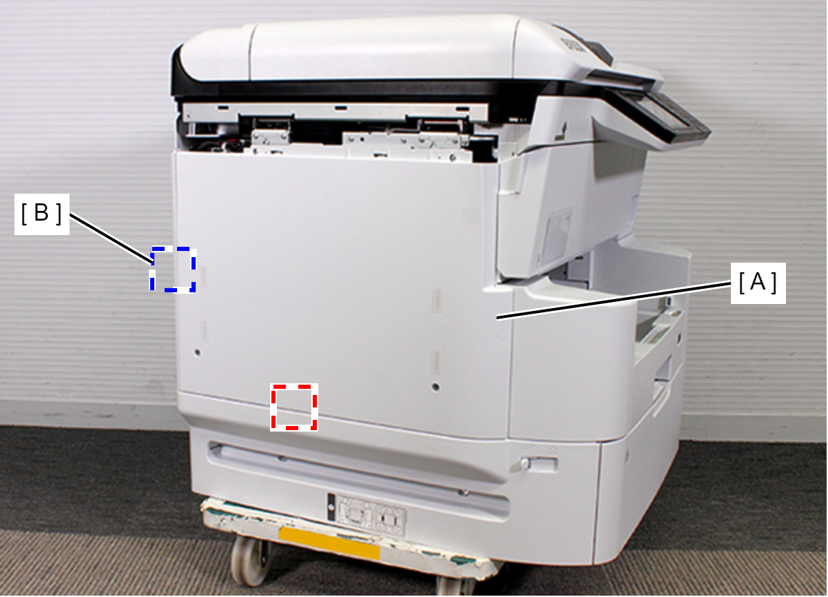
- Slide the Right SC Cover (A) while pushing the dent (B) of Right SC Cover, and release the three tabs. Remove the Right SC Cover (A).
- Remove one screw.
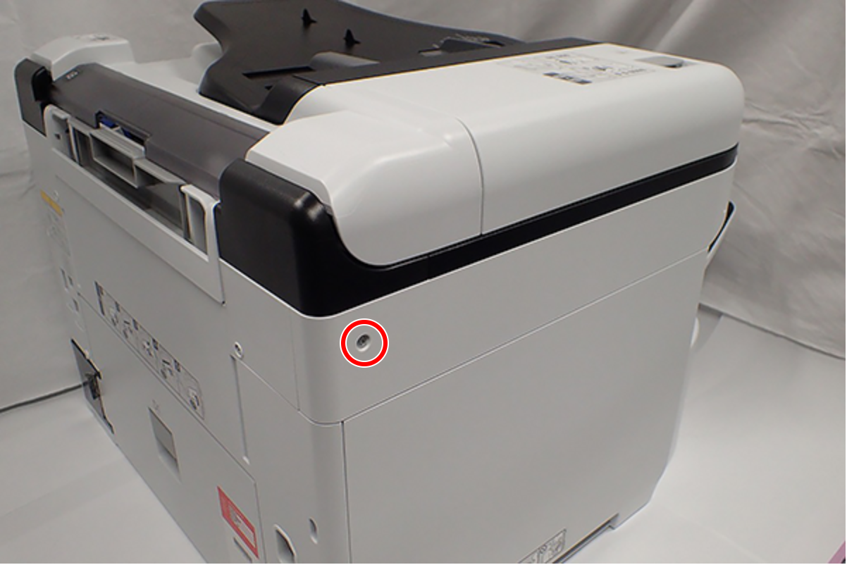
- : C.B.S-TITE-SCREW-3x8-F.ZN-3C
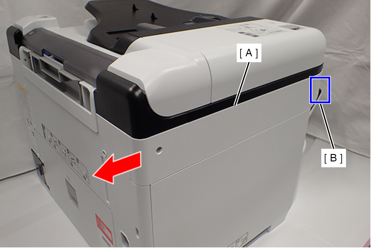
- Slide the Left SC Cover (A) while pushing the dent (B) of Left SC Cover, and remove it.
- Remove one screw, and remove the Lower SC Reinforcing Plate (A).
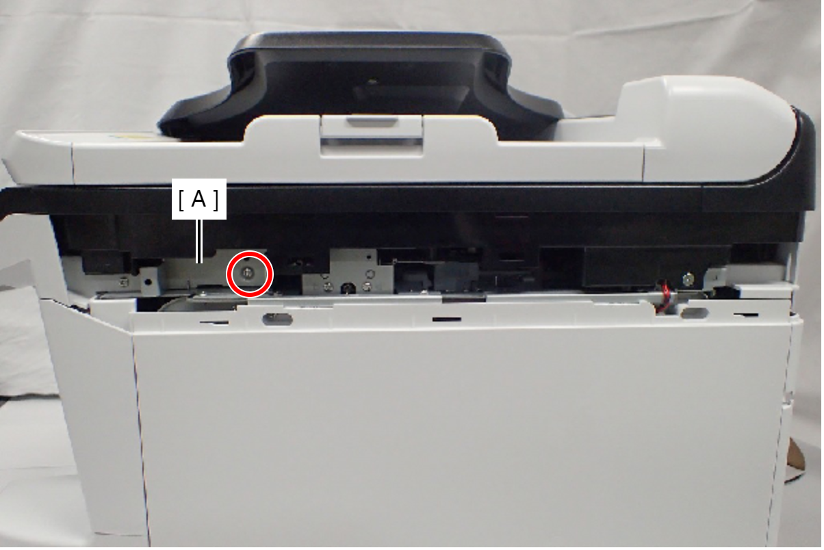
- : C.B.S-TITE-SCREW-3x8-F.ZN-3C
- Reattach the Lower SC Reinforcing Plate (A) in its portrait orientation, then secure it with the screw.
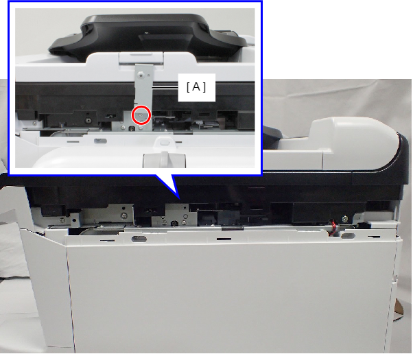
- : C.B.S-TITE-SCREW-3x8-F.ZN-3C
- Remove the screw.
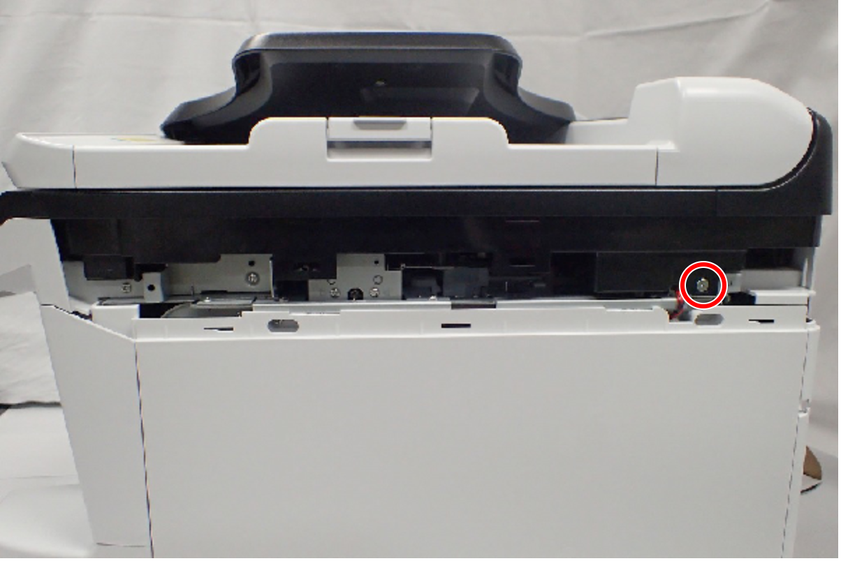
- : C.SHOULDER S-TITE,3X5
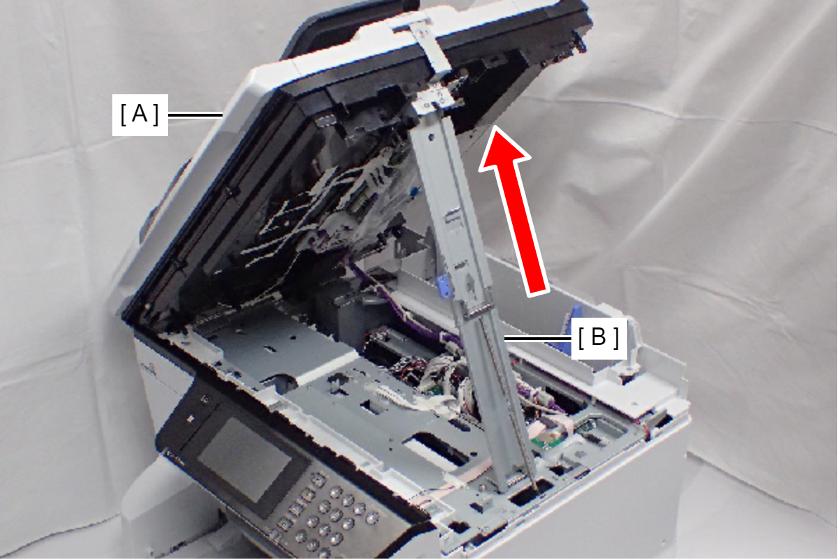
- Open the ADF/SCN Unit (A).
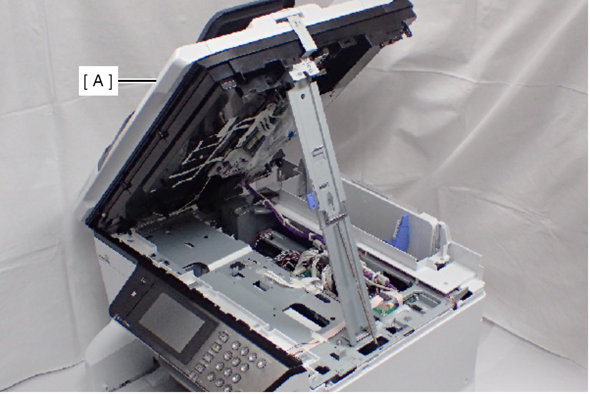
- Open the ADF/SCN Unit (A) and extend the support stand (B) as far as it goes, then support the ADF/SCN Unit with the support stand.
 Caution / 注意
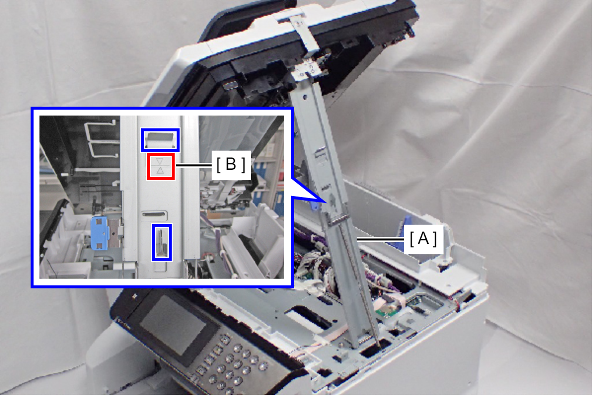
Make sure that the support stand (A) is fixed with the two hooks, and the two triangle marks (B) face to each other.
 Check Point / チェックポイント
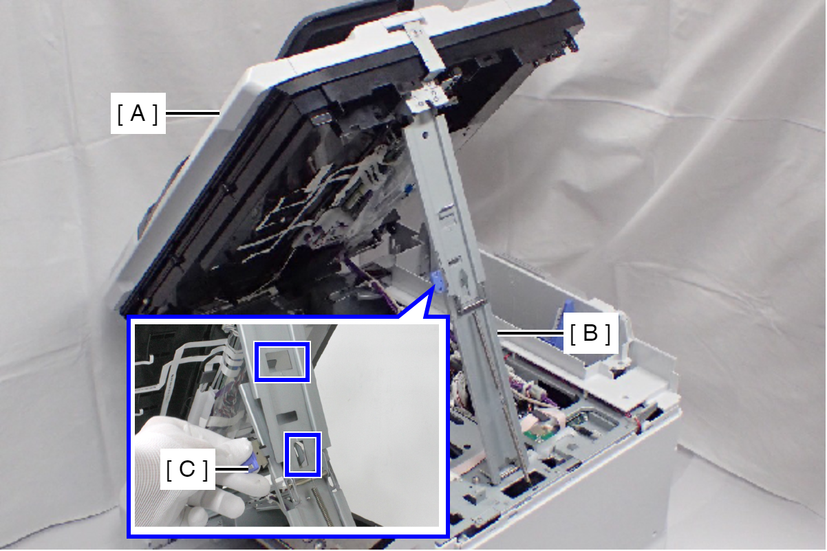
When closing the ADF/SCN Unit (A), press the switch (C) on the ADF/SCN support stand (B) and hold up the ADF/SCN Unit to disengage the two hooks, then fold the ADF/SCN support stand.
- Remove the screw.
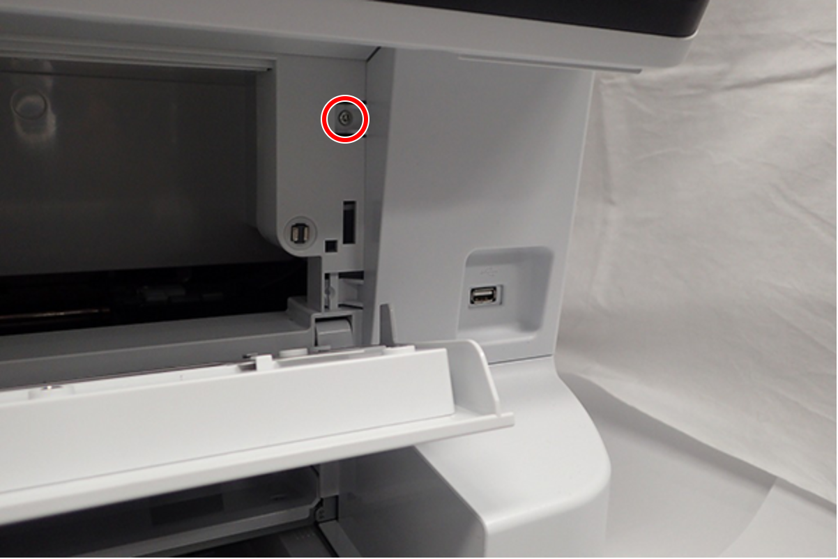
- : C.B.S-TITE-SCREW-3x8-F.ZN-3C
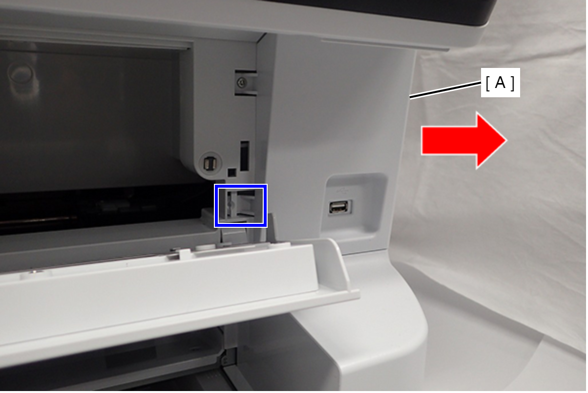
- Release the Hook, then slide the Front Right Cover (A) to direction of arrows and remove it.
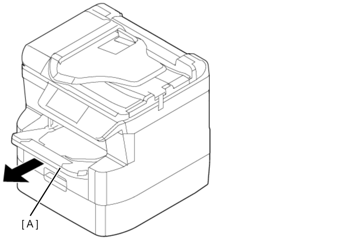
- Remove the Stacker Assy (A).
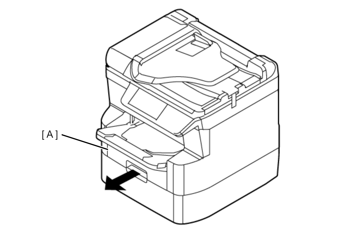
- Remove the Cassette Assy (A).
- Remove the two screws.
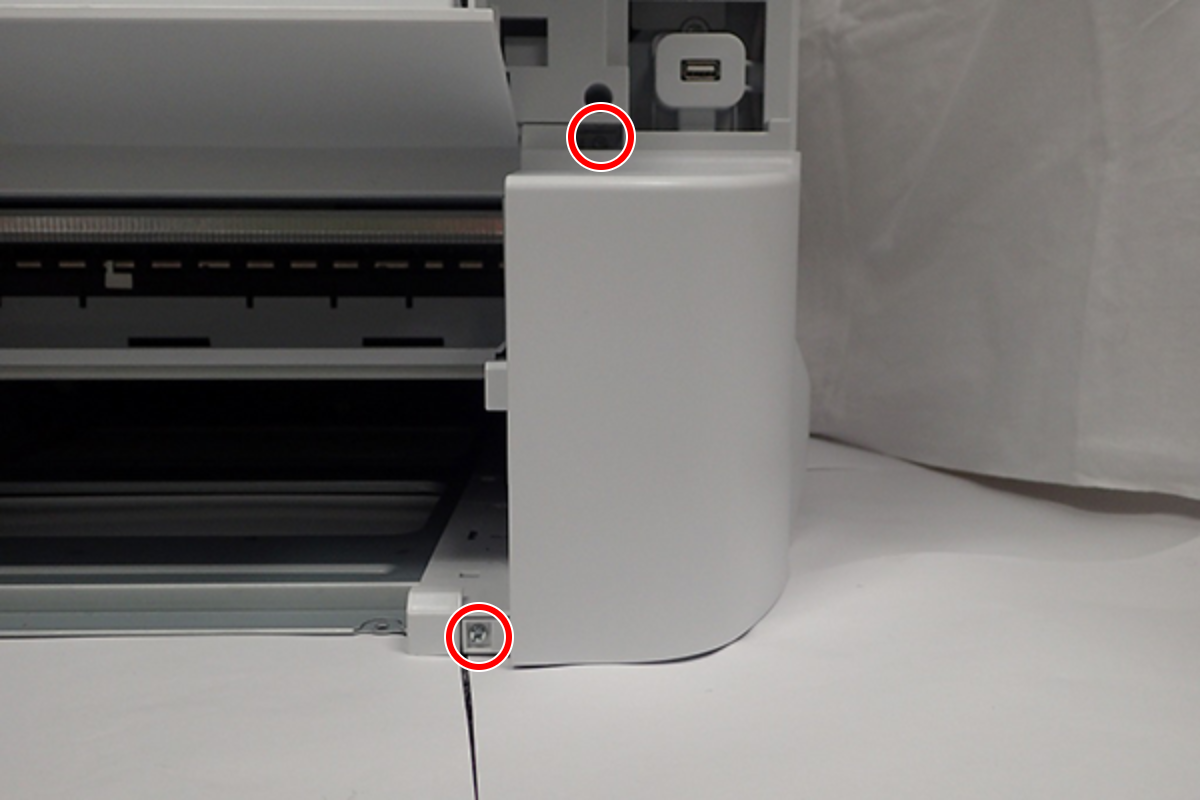
- : C.B.S-TITE-SCREW-3x8-F.ZN-3C
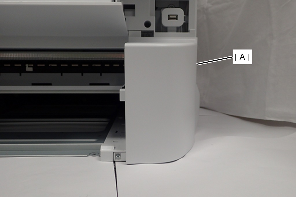
- Remove the Front Right Housing (A).
- Remove the four screws, then remove the Front Middle Frame (A).
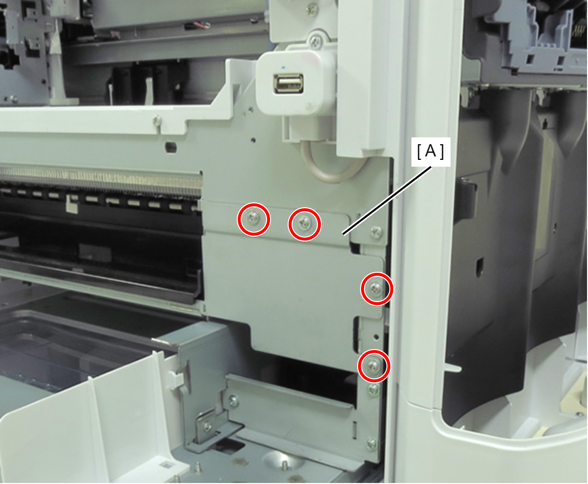
- : C.C.S-TITE-SCREW-3x5-F.ZN-3C
- Remove the four screws fastening the Right Housing (A).
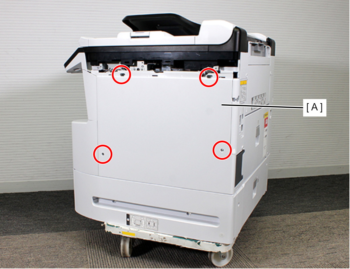
 : C.B.S-TITE-SCREW-3x8-F.ZN-3C
- Release the hook.
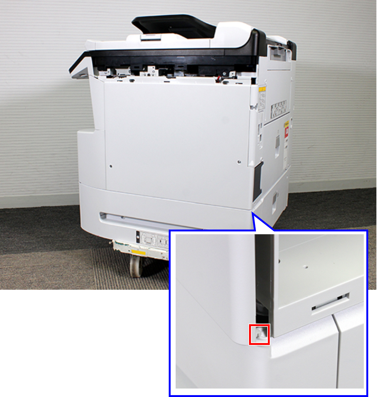
- Remove the two dowels.
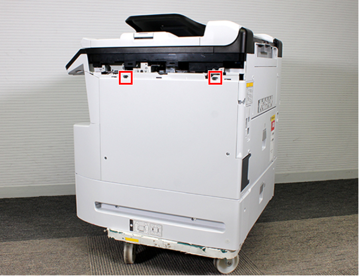
- Release the four hooks.
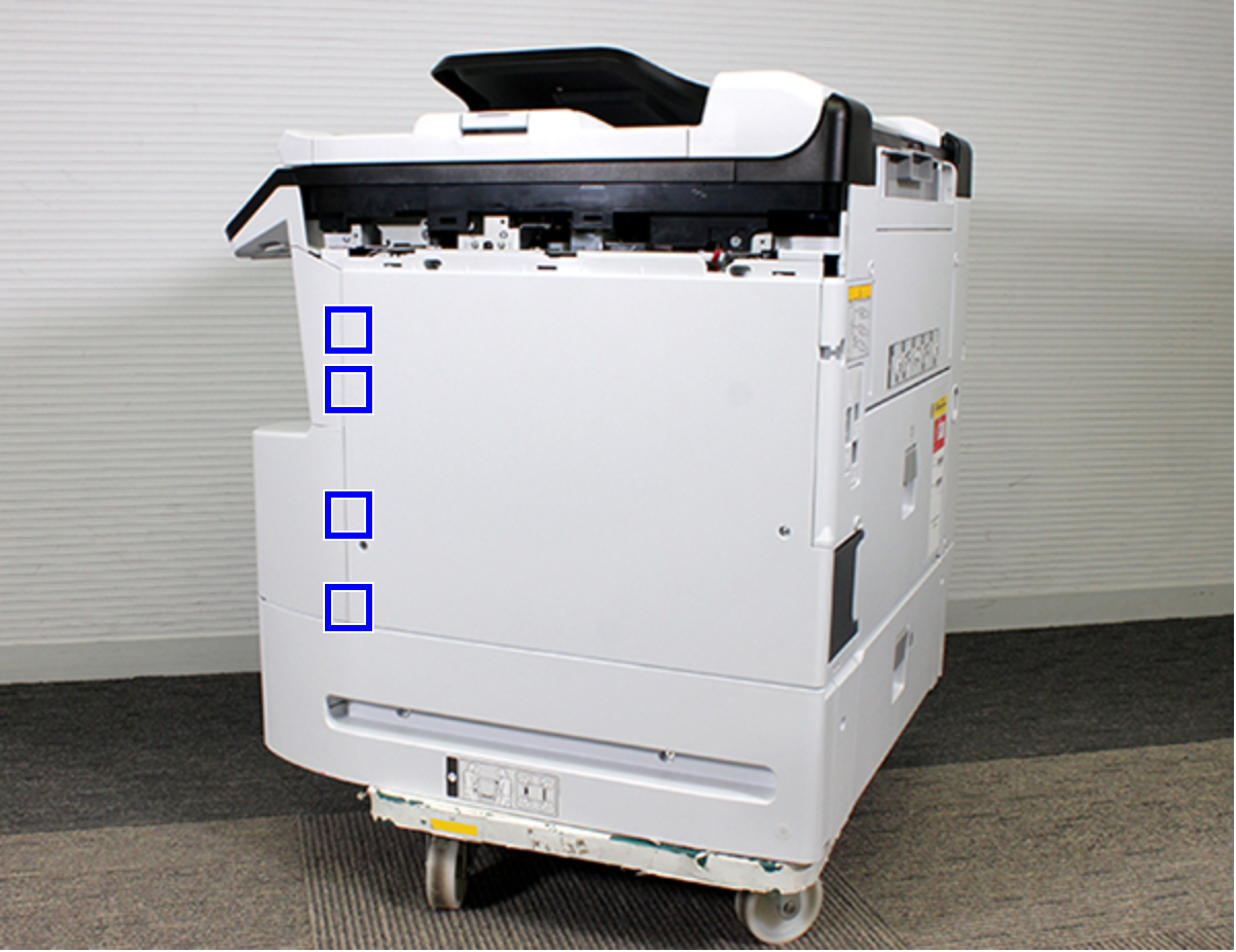
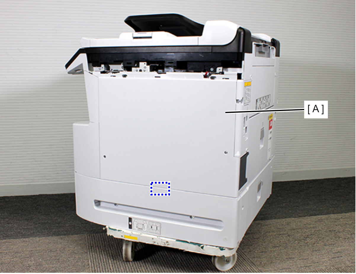
- Remove the Right Housing (A) while removing the rib.
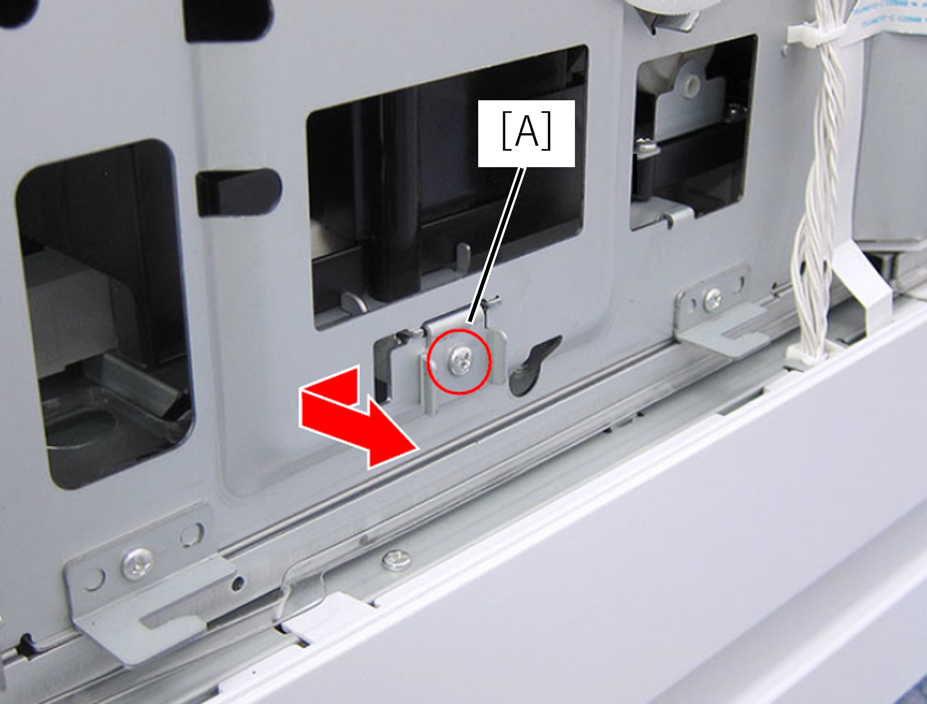
- Remove one screw and remove the IS holder plate (A) in the direction of the arrow.
- Insert the screwdriver into the hole and turn each of the two screws that secure the Ink System Assy (A) until you feel the screw is spinning free.
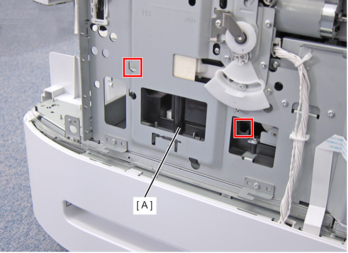 Check Point / チェックポイント
- Release the CR lock, then move the CR Unit to center before removing the Ink System Assy.
- The screws are not removed because there is a screw clamp.
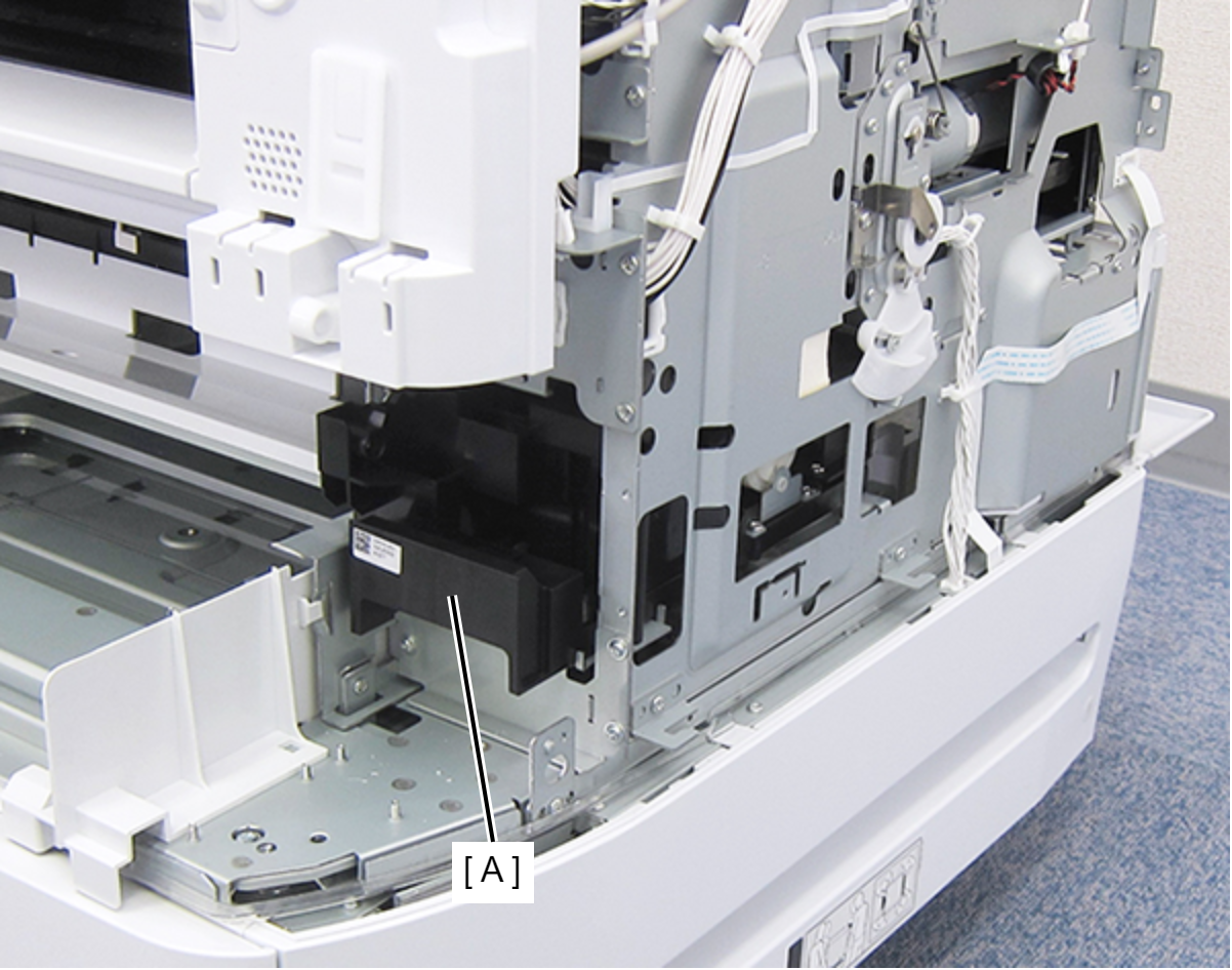
Pull the Ink System Assy (A) forward.
- Remove the four screws fastening the Left Housing (A).
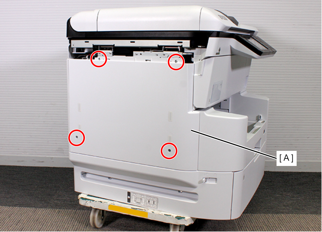
- : C.B.S-TITE-SCREW-3x8-F.ZN-3C
- Remove the two dowels.
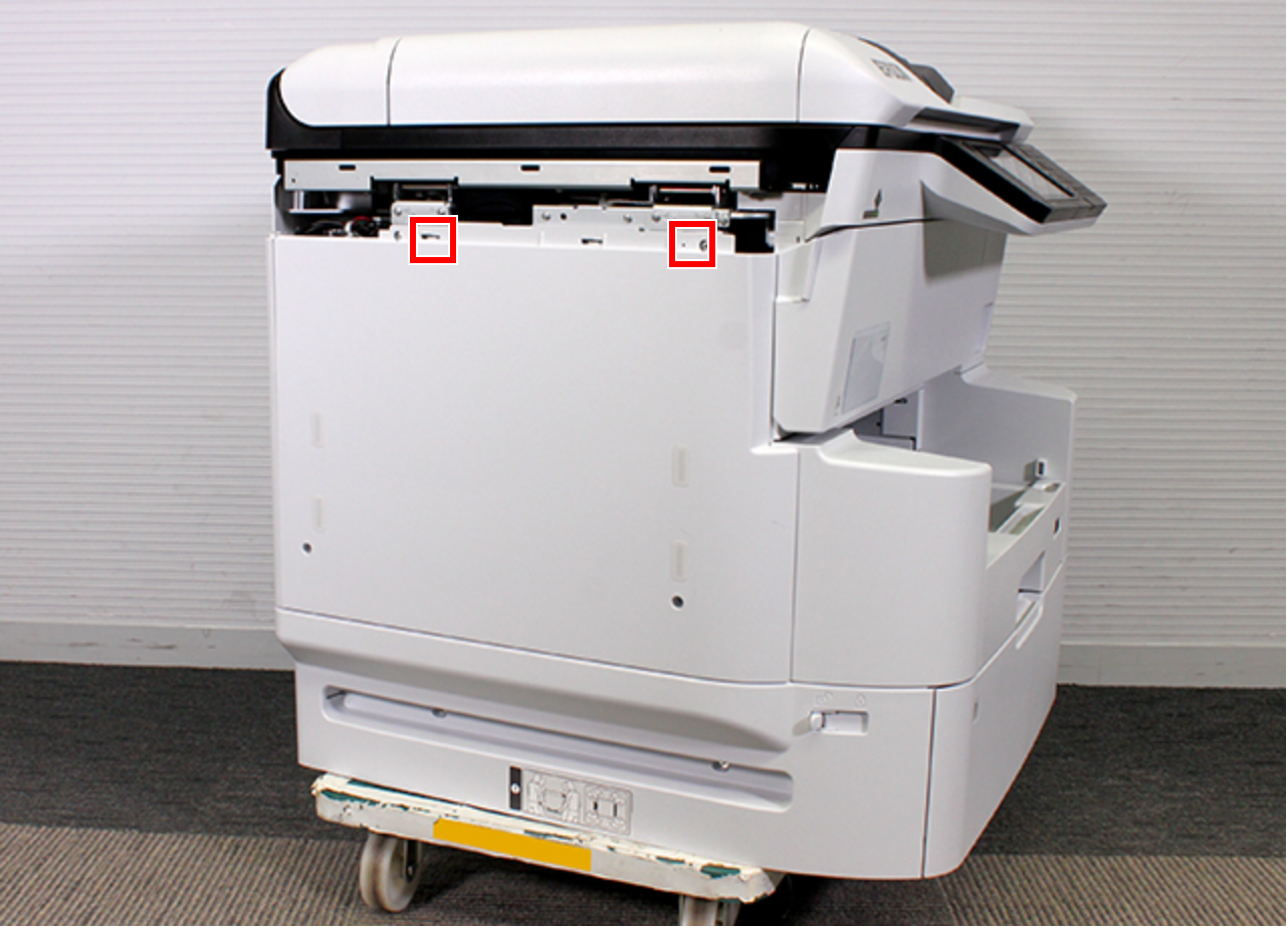
- Remove the rib on the front side while lifting up the Left Housing (A).
- Remove the rib on the back side while lifting up the Left Housing (A), release the hook (B) and then remove the Left Housing (A).
- Remove the screw, then remove the Left PG Cam Screw Holder (A) with the screw.
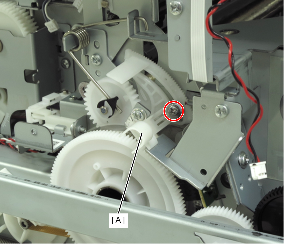
- : C.C.SCREW-3x6-F.ZN-3C
- Remove the screw, then remove the Anti Static Brush Plate (A).
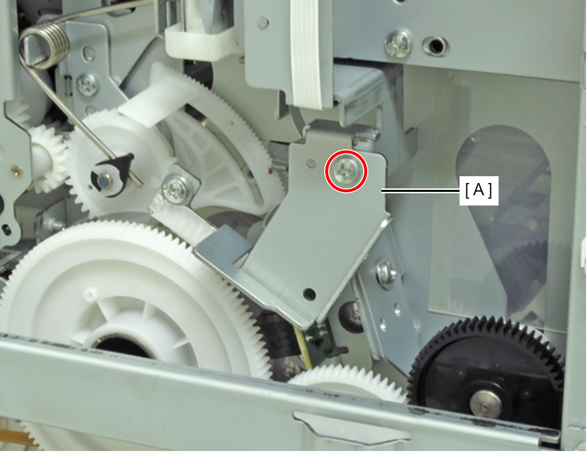
- : C.B.S-TITE-SCREW-3x6-F.ZN-3C
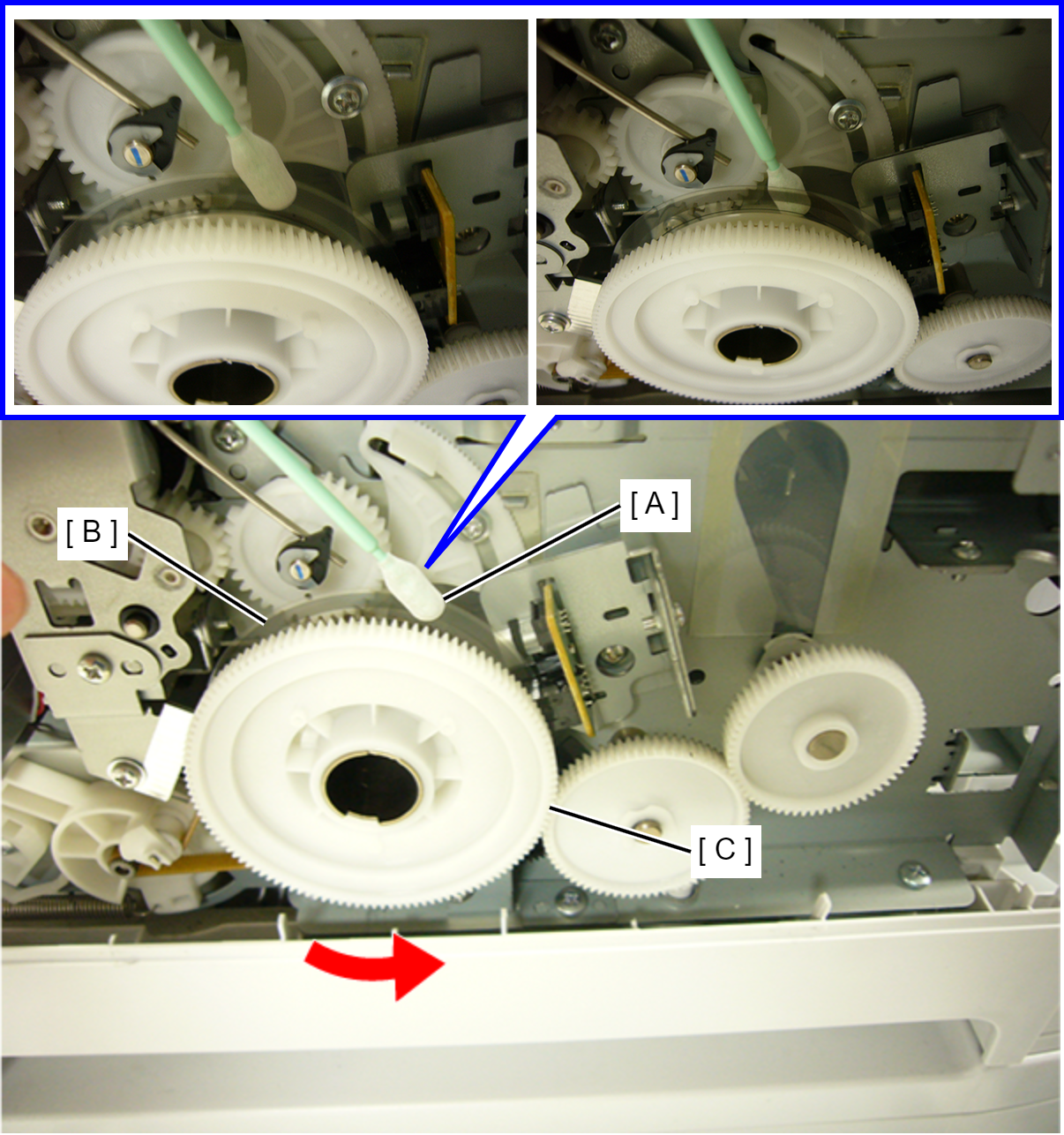
- Sork the Polyester Swab (A) with alcohol (Ethanol).
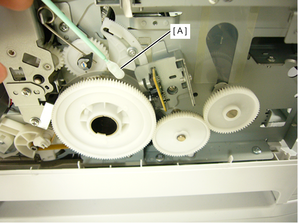
- Rotate the PF Gear (C) counterclockwise by hand and clean the scaled part on the PF Scale (B) with the Polyester Swab (A). (Clean both the front and back surfaces.)
 Caution / 注意
- Make sure not to add strong force to PF Scale.
- Clean the PF Scale until contamination does not adhere to the Polyester Swab.
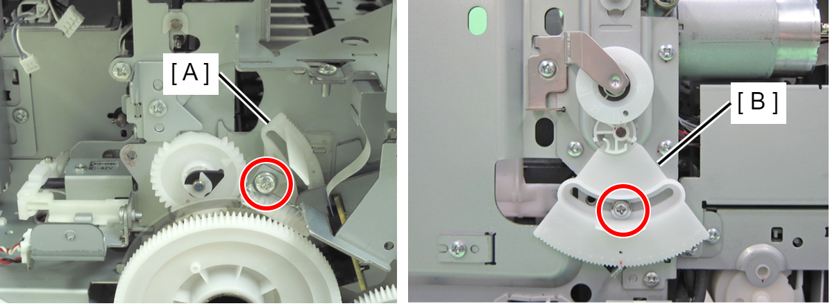
- Remove the screws of Left PG Cam (A) and Right PG Cam (B).
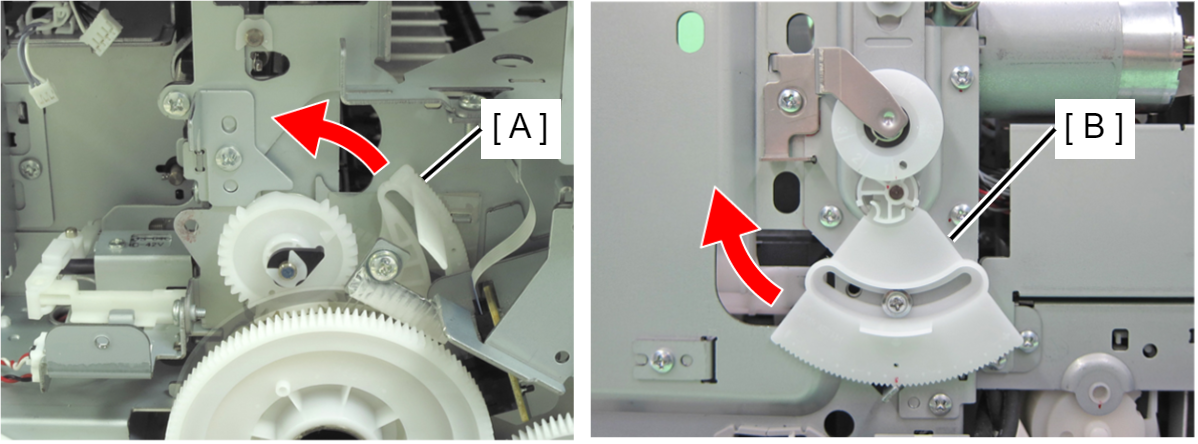
- Move the each PG Cam (A/B) one notch in the direction in which PG increases.
- Remove the five screws. (one of them is also securing the panel ground wire)
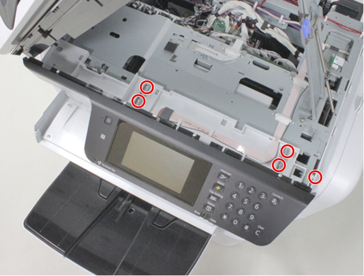
- : C.B.S-TITE-SCREW-3x8-F.ZN-3C
 Assembly / 組み立て
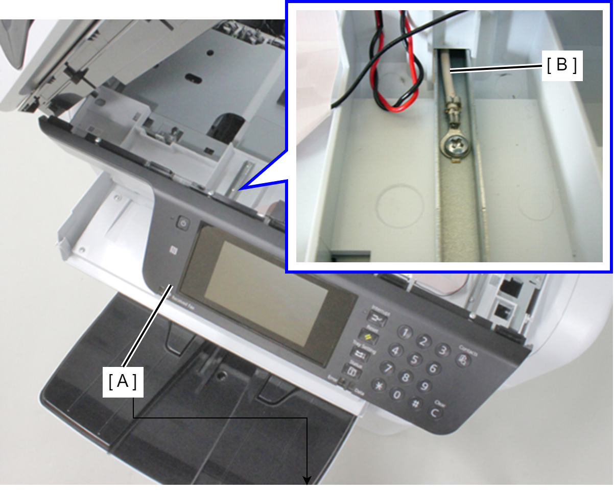
There is a place to fasten the grounding wire (B) together when fixing the panel (A).
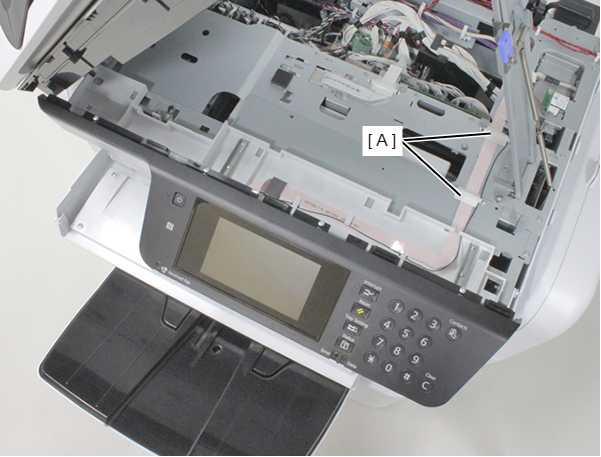
- Remove the two FFC clamps (A).
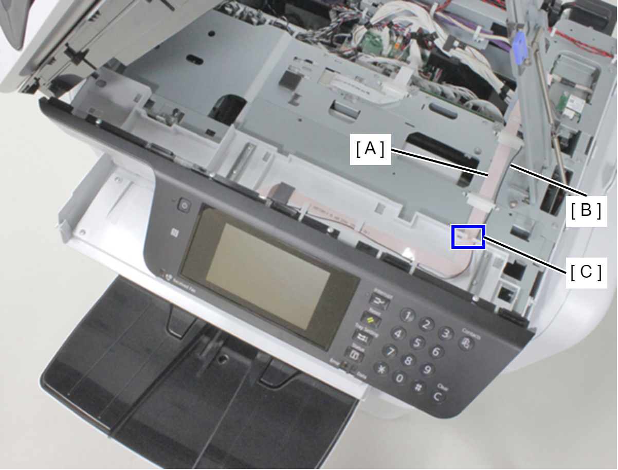
- Release the Panel FFC (A) and the grounding wire (B) from the guide (C).
- Open the Front Cover Assy (A).
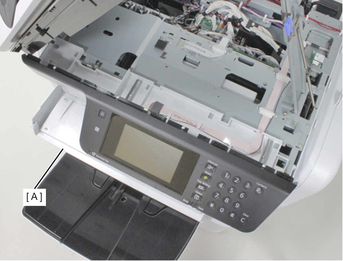
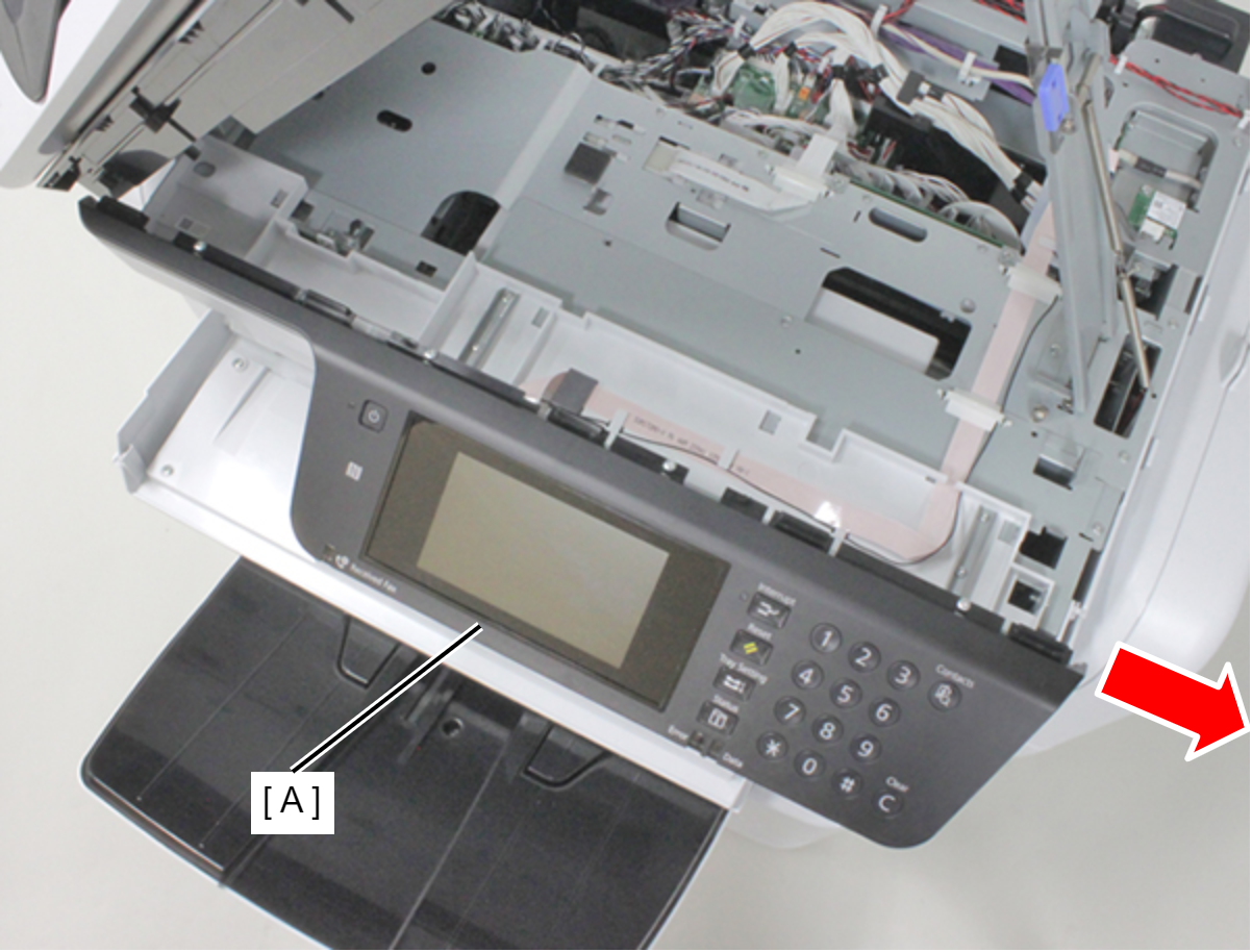
- Slide the panel unit (A) rightward to remove it.
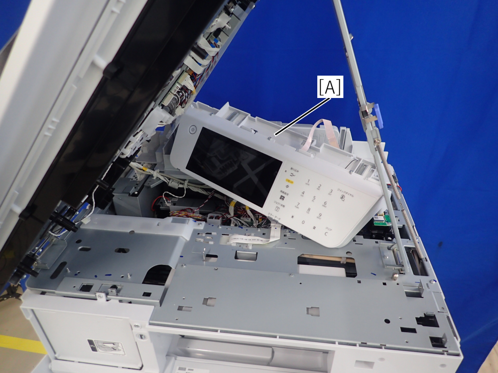
- Put the Panel Unit (A) at the rear side of the printer.
- Remove the seven screws, then remove the Front Housing Frame Assy (A).
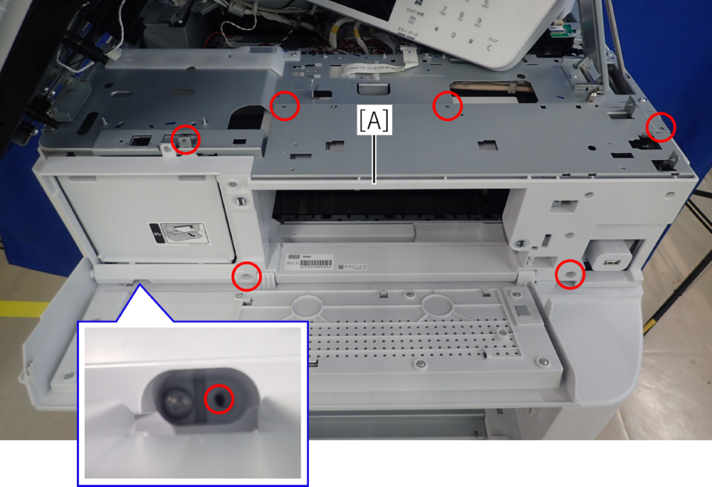
- : C.B.S-TITE-R-SCREW-3x6-F.ZN-3C
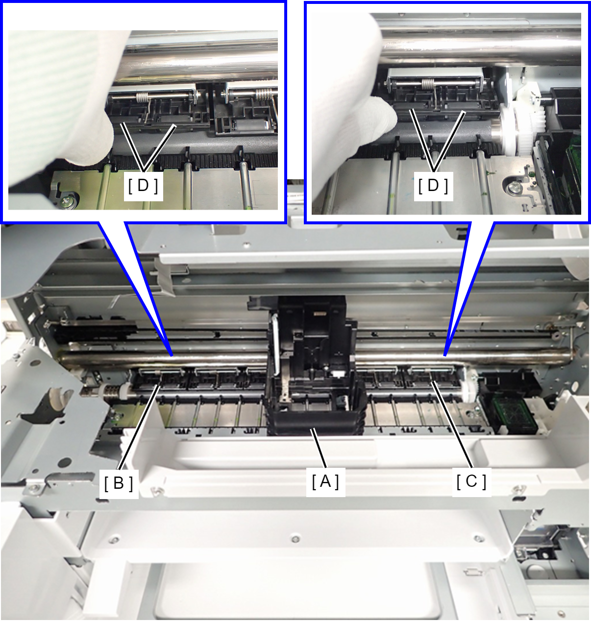
- Move the CR Unit (A) to the center of the product to make it possible to access the Driven Rollers (D) on the Paper Guide Upper Left (B) and the Paper Guide Upper Right (C).
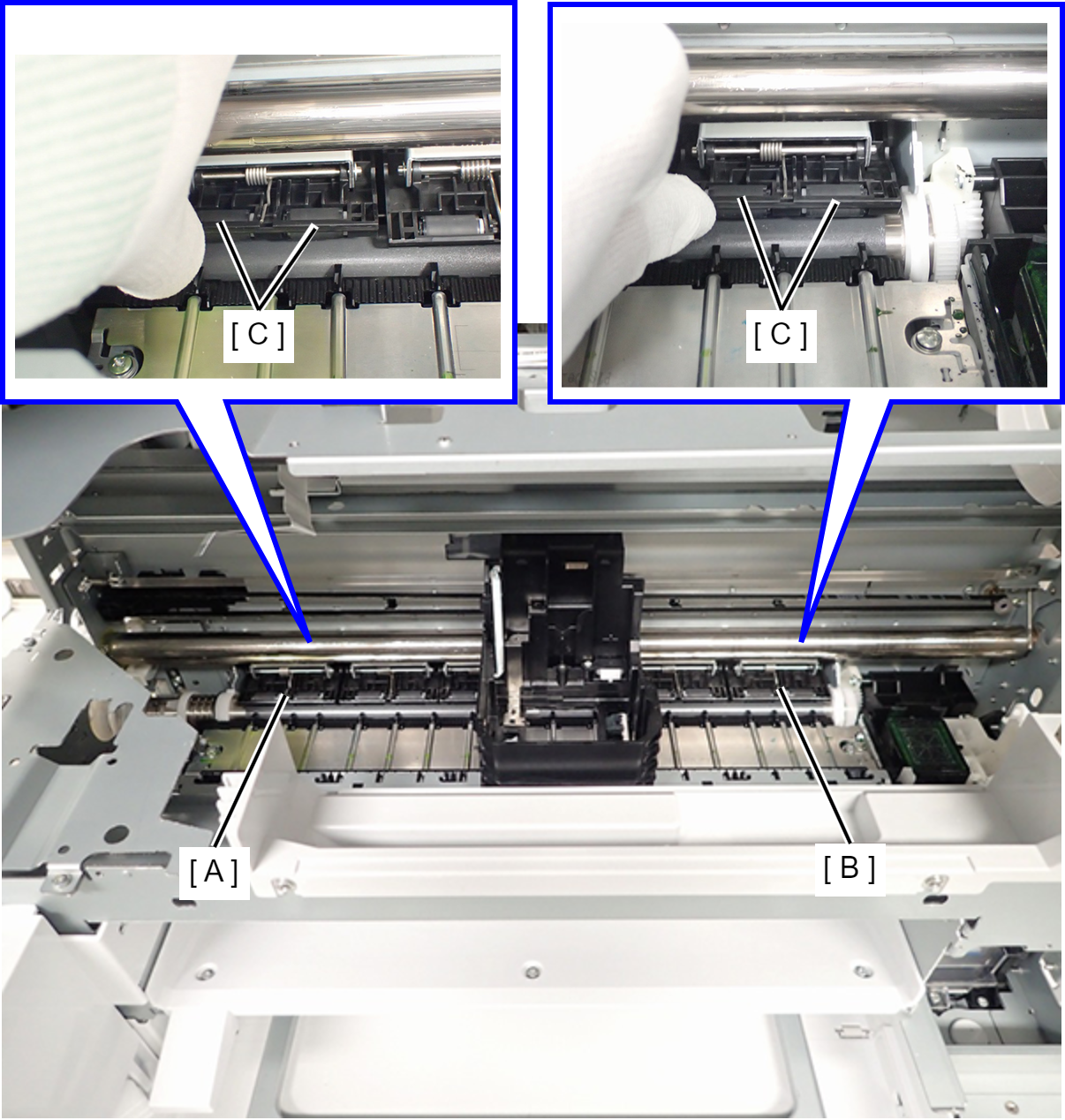
- Hold up the Paper Guide Upper Left (A) or Paper Guide Upper Right (B) by finger, and push the edge of Driven Roller (C) (two position). Remove the Driven Roller (C).
 Assembly / 組み立て
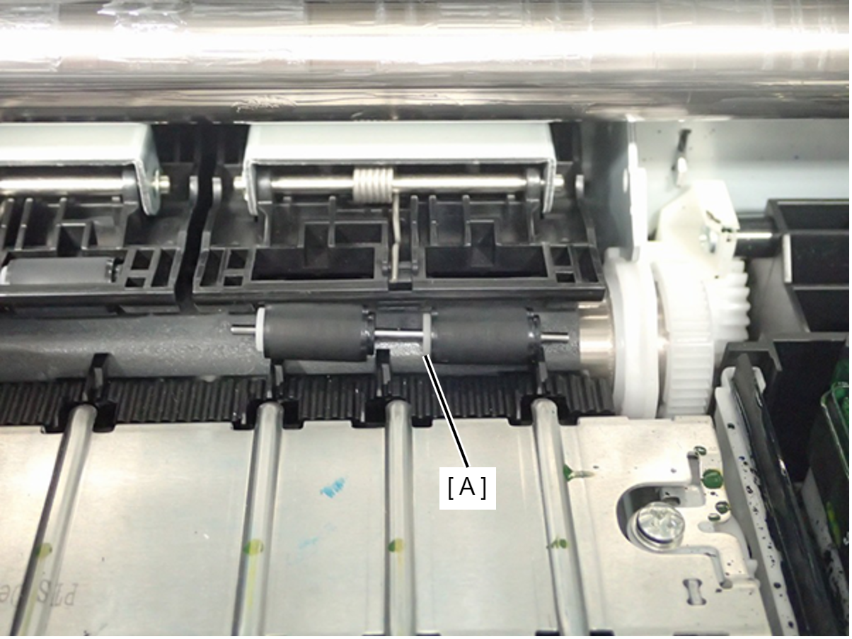
- Put the Driven Roller (A) aligned in the Paper Guide Front.
Hold up the Paper Guide Upper Left or Paper Guide Upper Right (A), and move the Driven Roller (B) to installing position.
- Push the edge (C) of Driven Roller (two position), and install the Driven Roller (B).
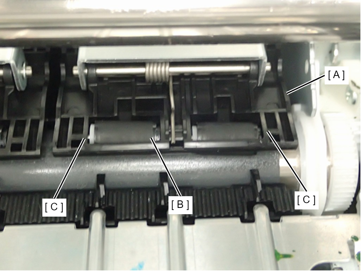
Caution / 注意Driven Roller has installation direction. Therefore, make sure to install the Drive Roller correct direction. (The white part of Drive Roller faces the center)
- Put the Driven Roller (A) aligned in the Paper Guide Front.
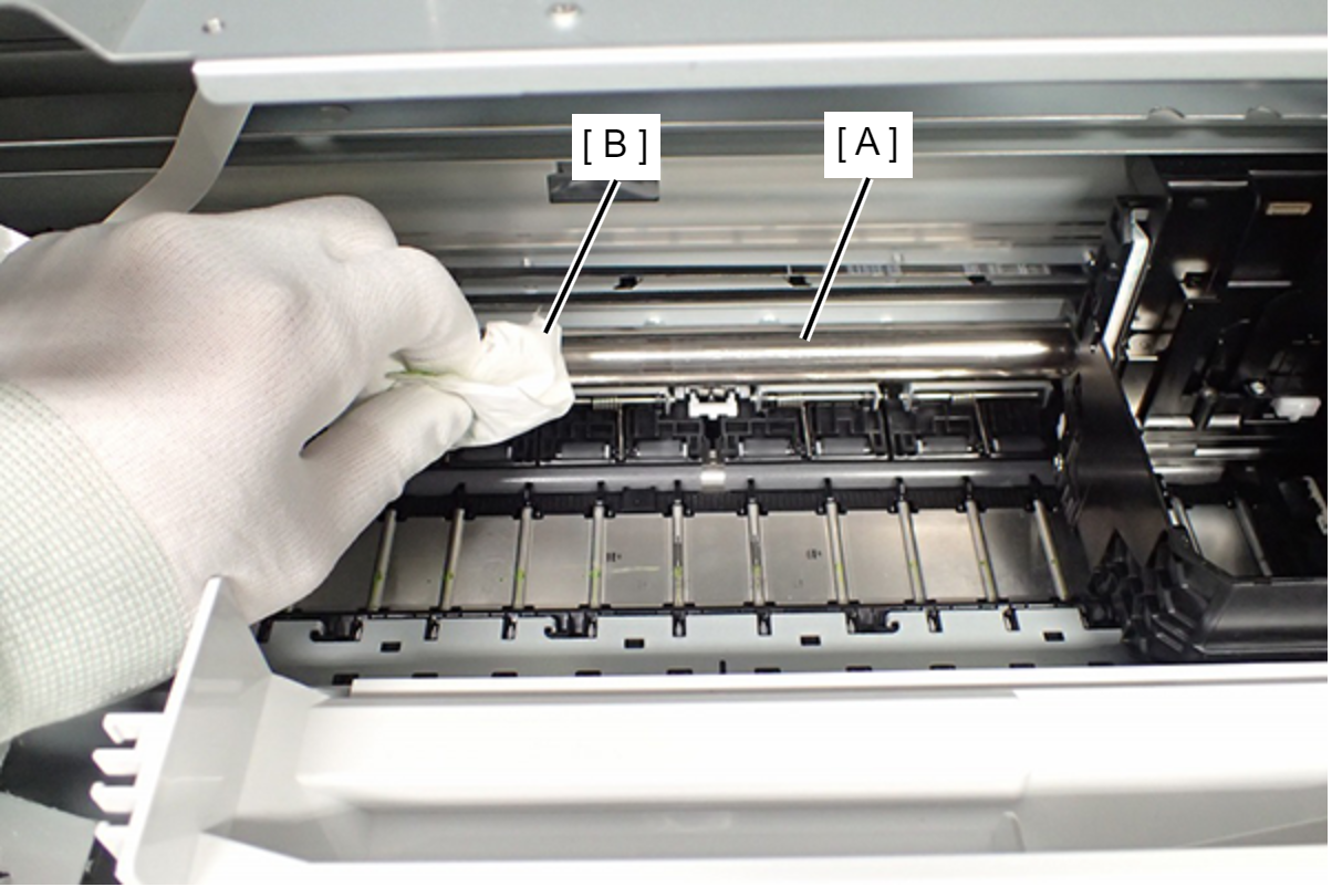
- Wipe off the Grease from CR Shaft (A) with dry clean cloth (B).
 Check Point / チェックポイント
Make sure wipe off the Grease on back side surely too.
CR Shaft can be rotate by rotate the gear of the APG Drive Assy (A).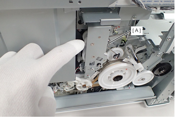
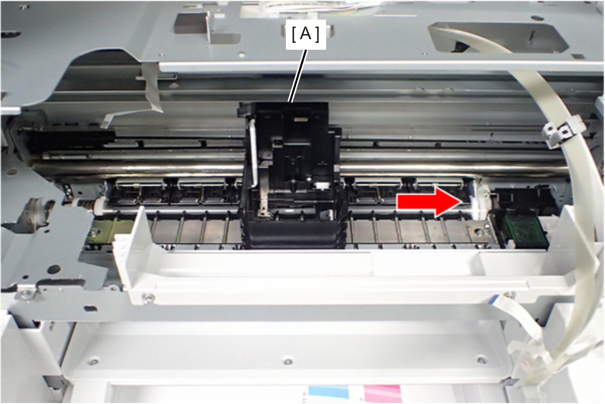
- Move the CR Unit (A) to Home Position (Right side of printer).
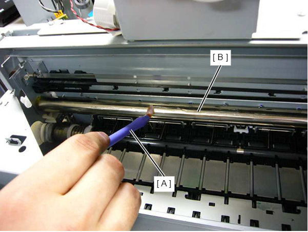
- Attach the Grease (G-97) to CR Shaft (B) by using the writing brush (A).
- Move the CR Unit (A) to Full side (Left side of printer).
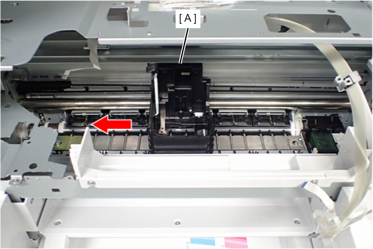
- Attach the Grease (G-97) to CR Shaft (B) by using the writing brush (A).
- Rotate the gear of the APG Drive Assy (A), and make the back side of the CR Shaft visible.
- Attach the Grease (G-97) to back side of CR Shaft (B) by using the writing brush (A).
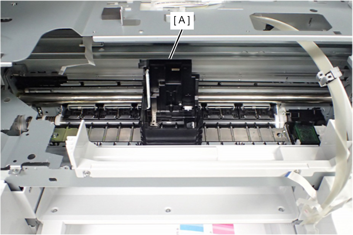
- Move the CR Unit (A) to the center of the printer.
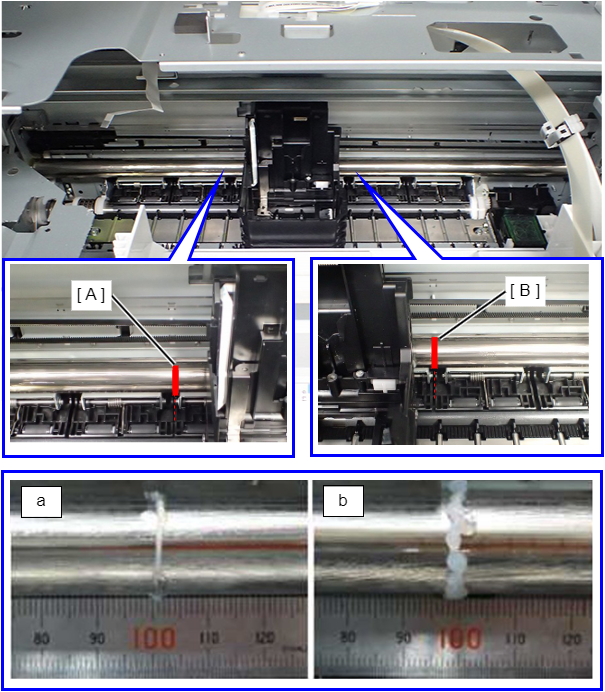
- Attach the Grease to two position of the CR Shaft. (Regarding the lubrication amount, refer to above figure. a: Minimum Standard, b: Maximum Standard)
- Full side (Left side of printer): Position (A) is between the Paper Guide Upper Left and the Paper Guide Upper Center.
- Home position side (Right side of printer): Position (B) is between the Paper Guide Upper Right and the Paper Guide Upper Center.
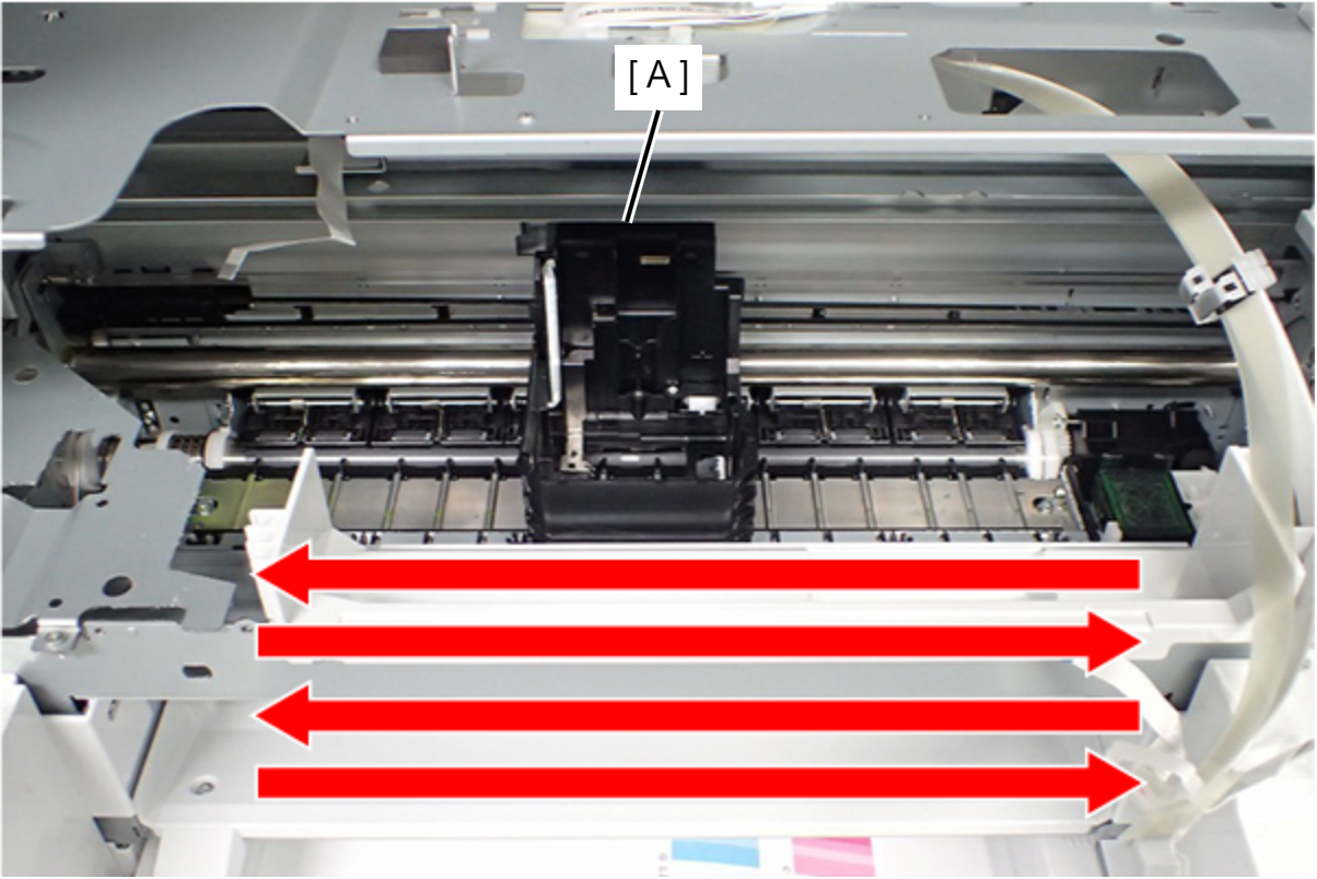
- Move the CR Unit two reciprocations.
- Confirm the Grease remained on “Bearing part of CR Unit” and “edge part of CR Shaft”. (If remained grease is more than maximum standard, make sure to remove the remained grease.)
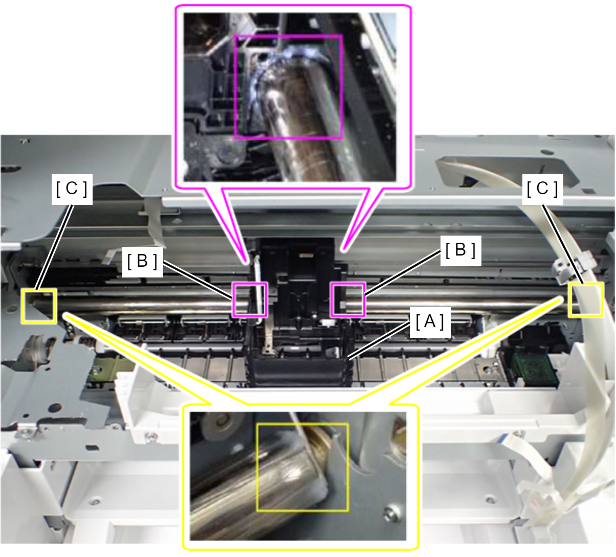
- Assemble the product up to the product state (state where it can be activated).
- Start the Printer by Service Support Mode.(Starting Service Support Mode)
- Select ”04 Maintenance” from Service Support Mode.
- Select ”410 Regular Maintenance”.
- Select ”41002 After performed”.