
CSIC Relay Board
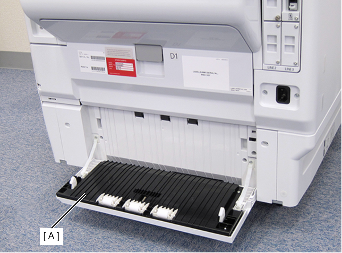
- Open the Paper Jam Clear Cover (A).
- Remove the screw on the rear side of the product, then remove the Paper Jam Clear Cover Holder (A).
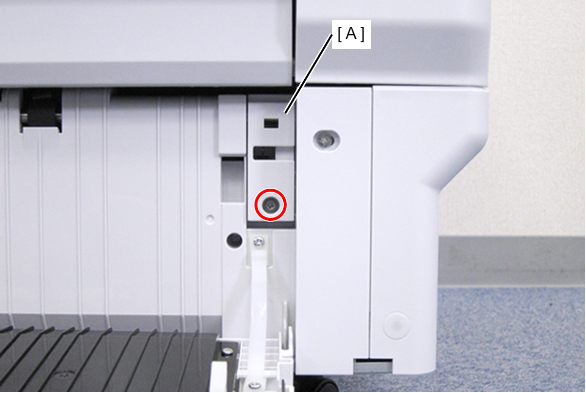
 : C.B.S-TITE-SCREW-3x8-F.ZN-3C
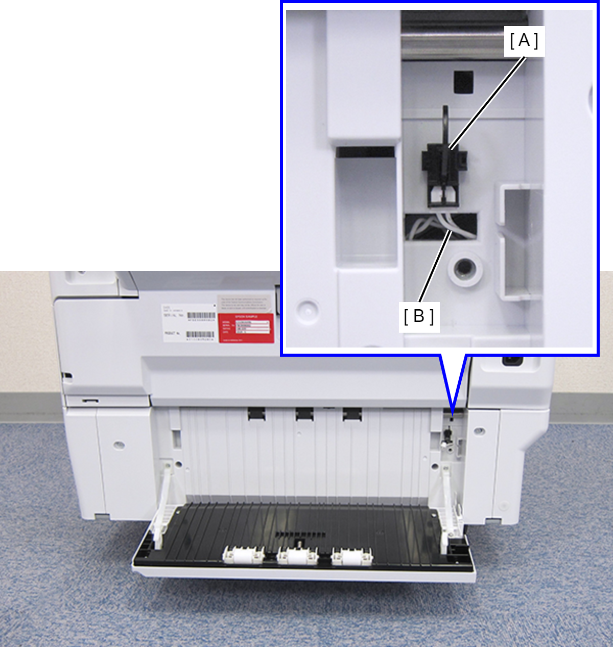
- Disconnect the cable (B) from the connector of the Paper Jam Clear Cover Sensor (A).
- Remove the four screws that secure the Rear RIPS Housing Assy (A).
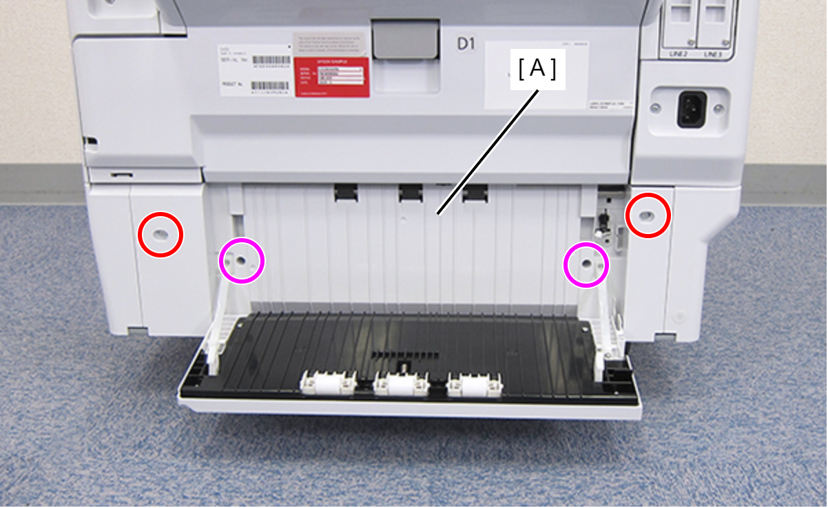
 : C.SHOULDER S-TITE,3X5
 : C.B.P-TITE-SCREW-3x10-F.ZN-3C
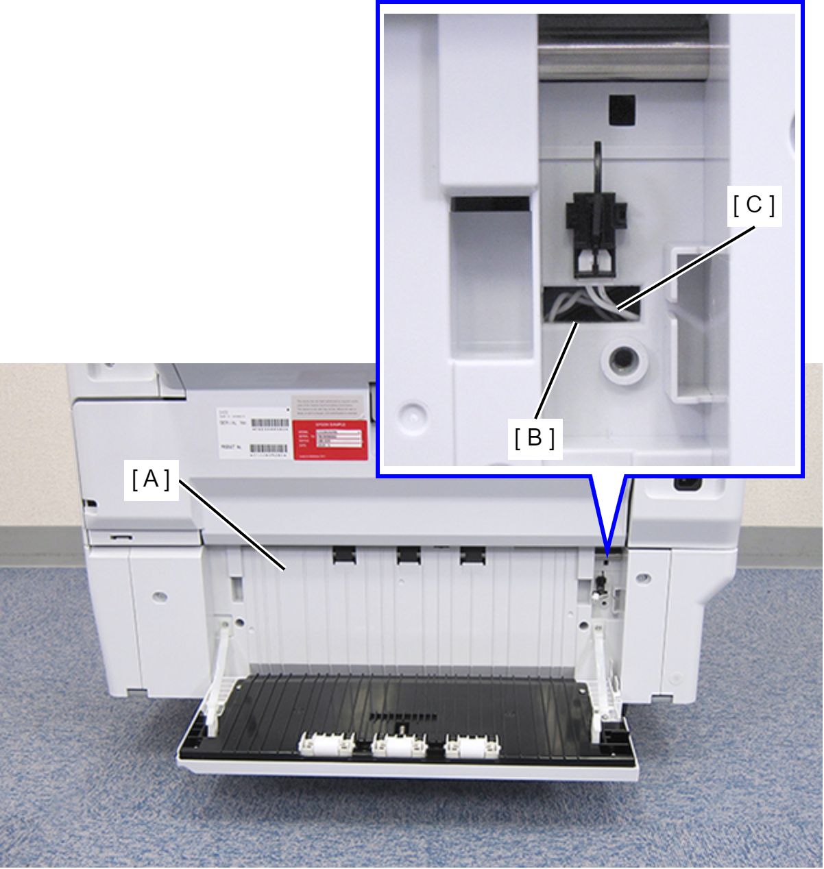
- Remove the Rear RIPS Housing Assy (A) pulling out the cable (C) through the hole (B) of the assy.
 Assembly / 組み立て
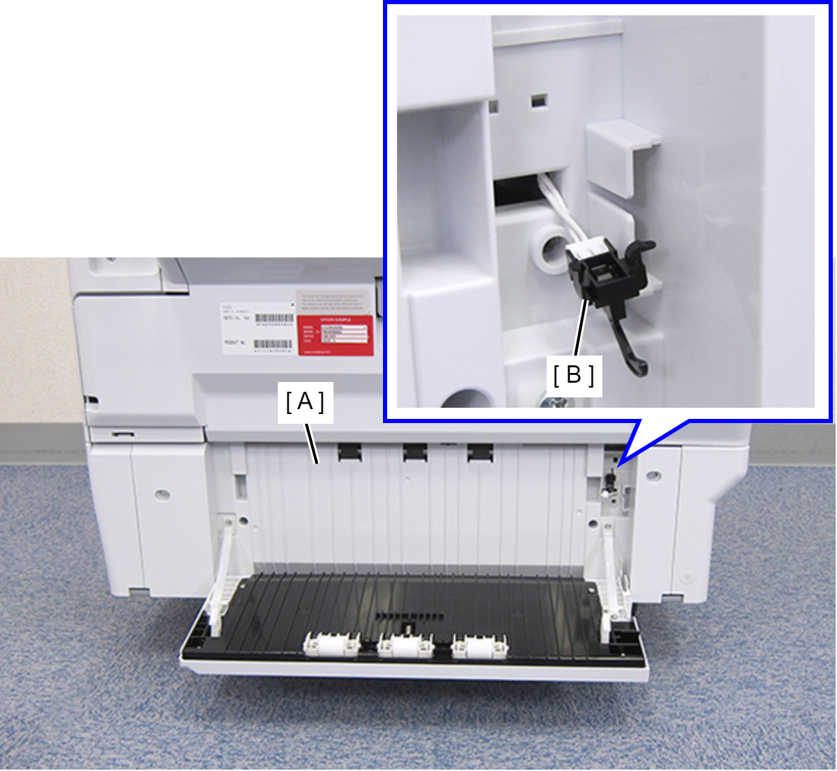
Before reinstalling the Rear RIPS Housing Assy (A), remove the Paper Jam Clear Cover Sensor (B). After connecting the cable, install the sensor to the Rear RIPS Housing Assy.
- Remove one screw.
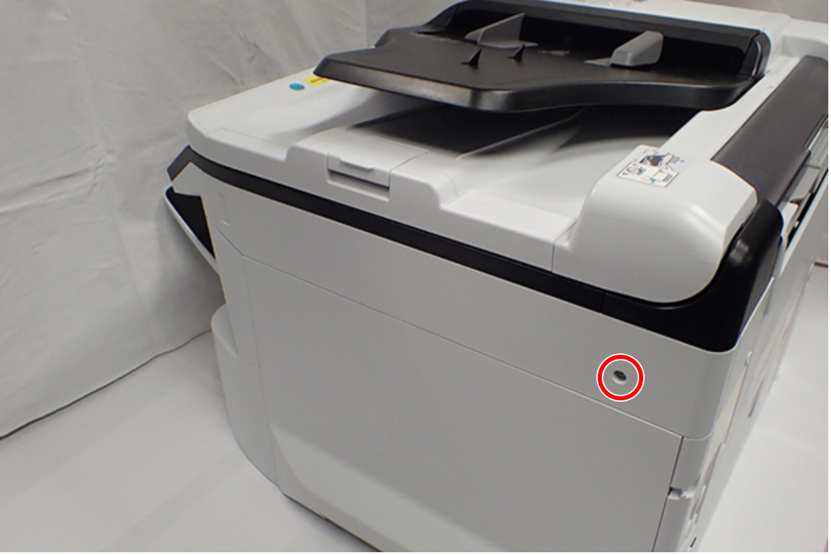
- : C.B.S-TITE-SCREW-3x8-F.ZN-3C
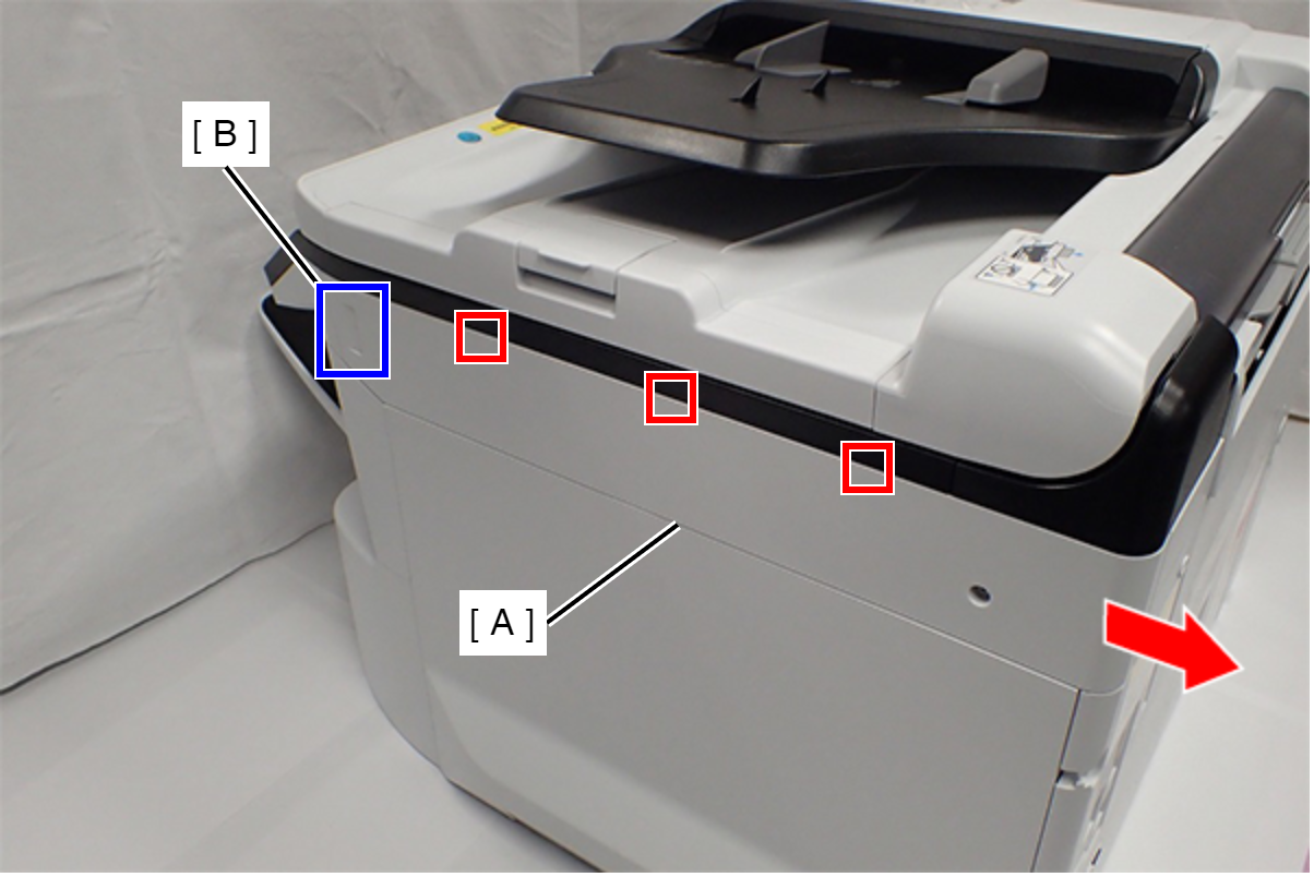
- Slide the Right SC Cover (A) while pushing the dent (B) of Right SC Cover, and release the three tabs. Remove the Right SC Cover (A).
- Remove the four screws fastening the Right Housing (A).
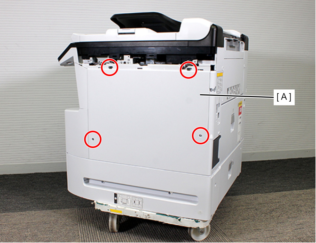
- : C.B.S-TITE-SCREW-3x8-F.ZN-3C
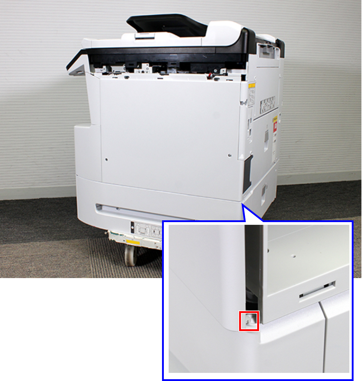
- Release the hook.
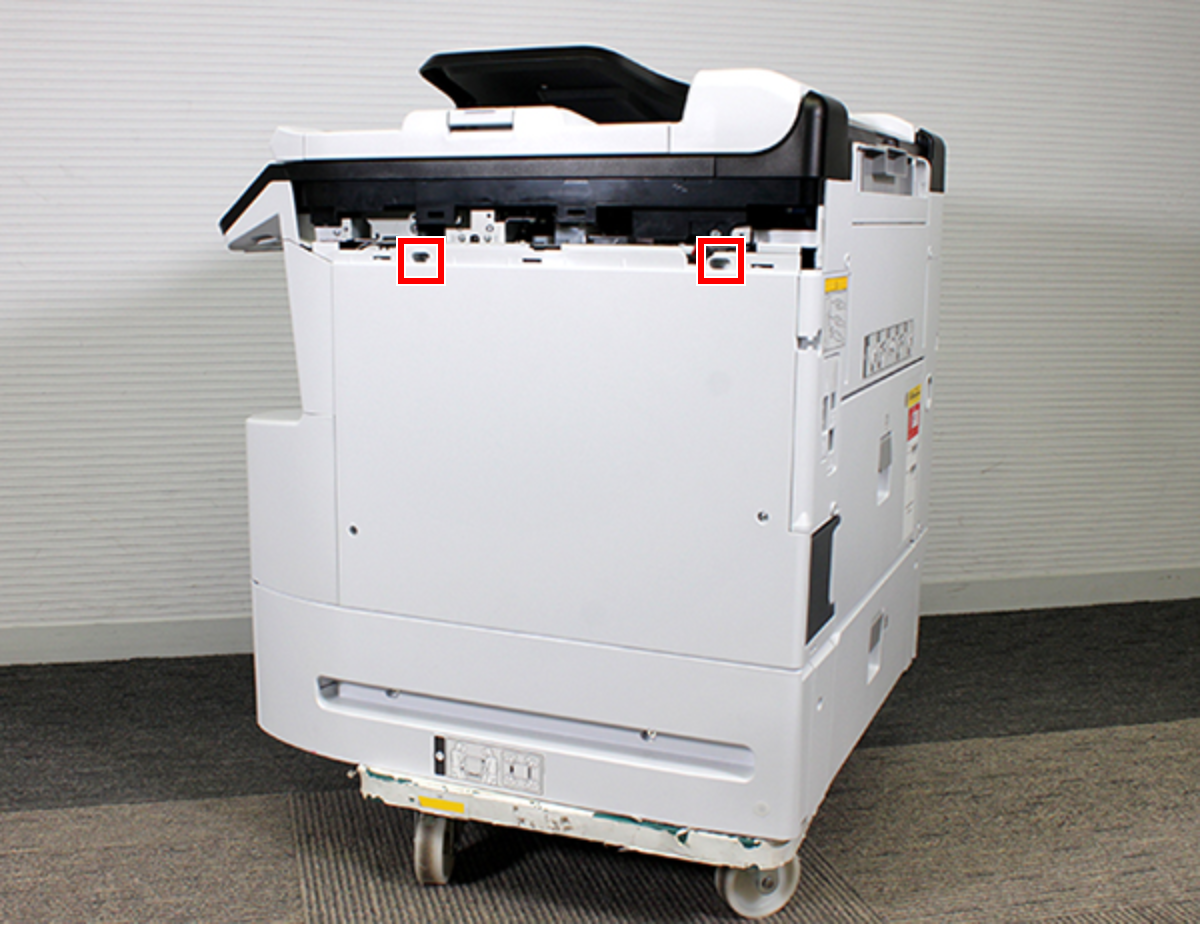
- Remove the two dowels.
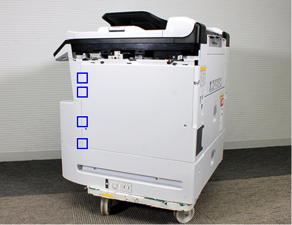
- Release the four hooks.
- Remove the Right Housing (A) while removing the rib.
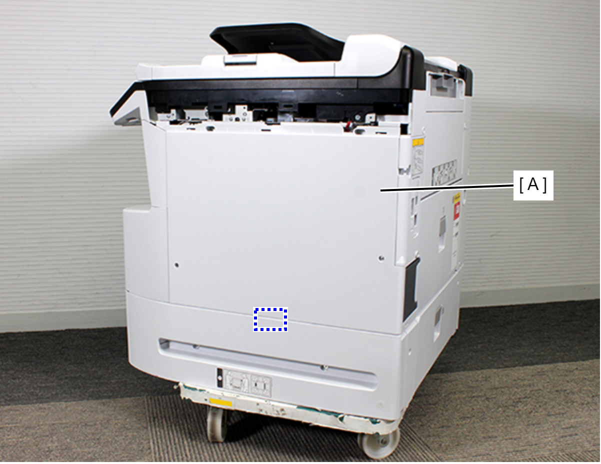
- Remove the two screws fastening the Right RIPS Housing Assy (A).
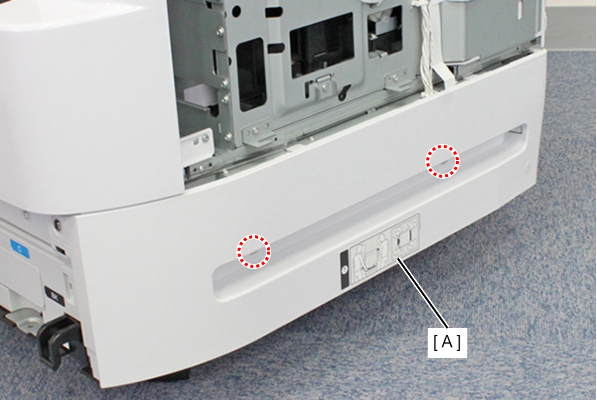
- : C.SHOULDER S-TITE,3X5
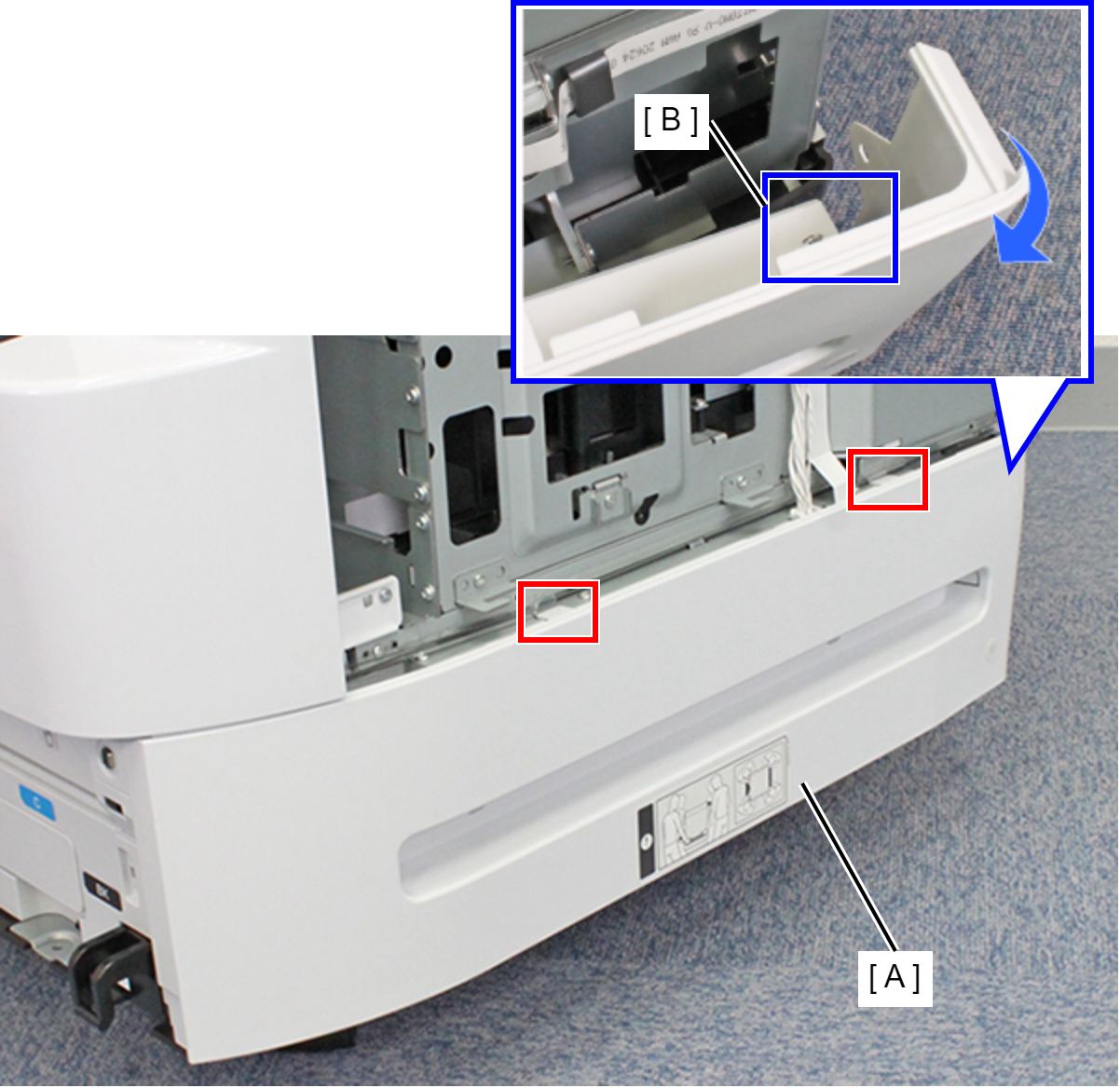
- Lift the Right RIPS Housing Assy (A) and rotate in the direction of the arrow while releasing the two hooks to release the interfering unit (B) behind the Right RIPS Housing Assy (A).
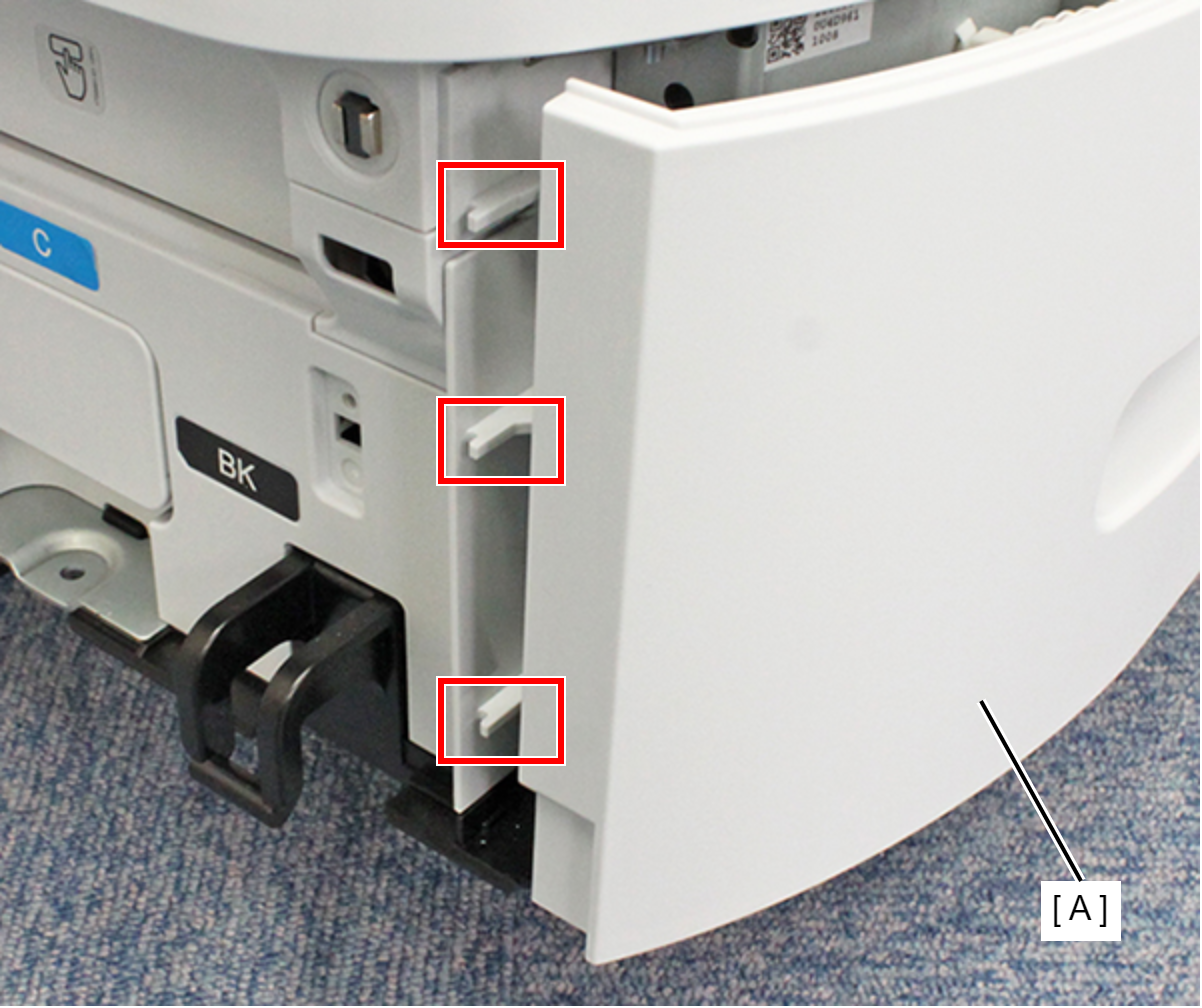
- Remove the three ribs on the front side of the Right RIPS Housing Assy (A) and remove the Right RIPS Housing Assy (A).
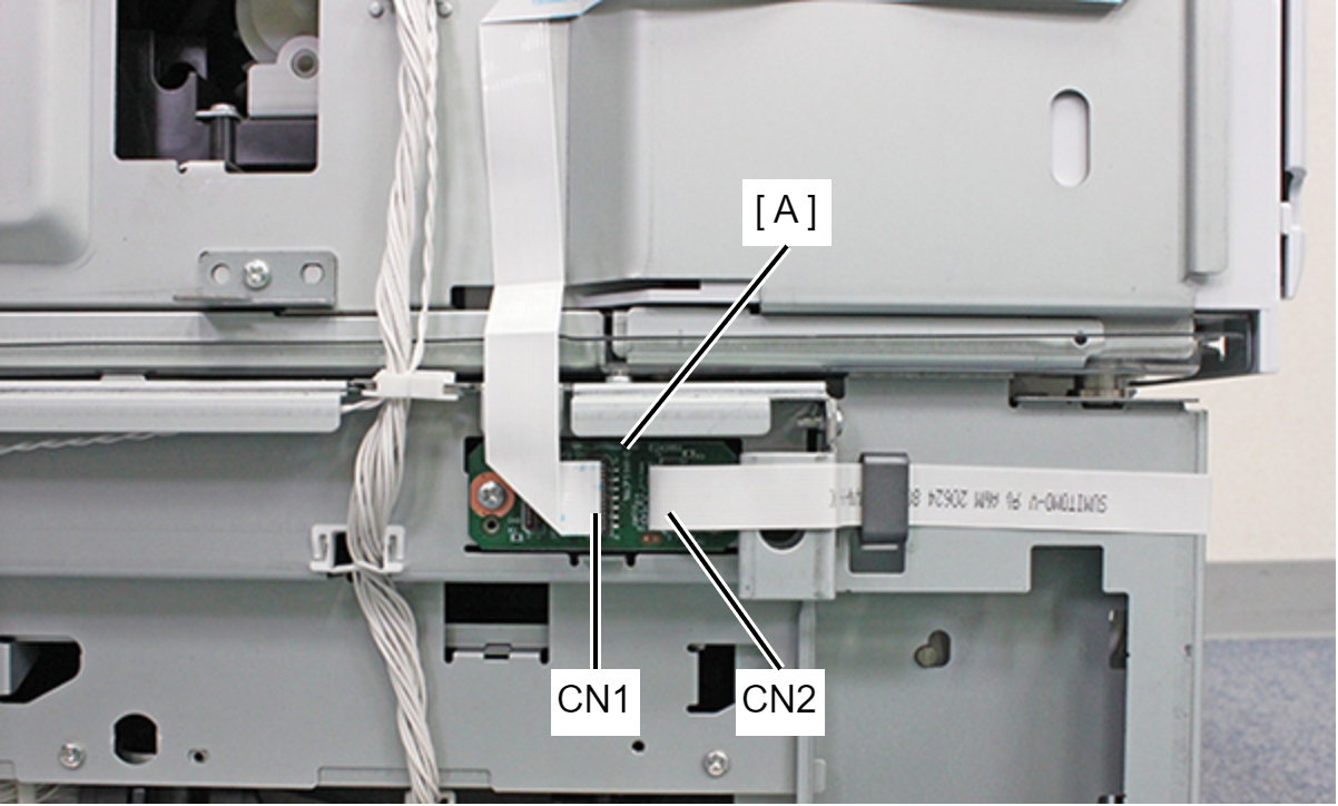
- Remove the CRCM FFC from the connectors (CN1, CN2) of the CSIC Relay Board (A).
- Remove the two screws, and remove the CSIC Relay Board (A).
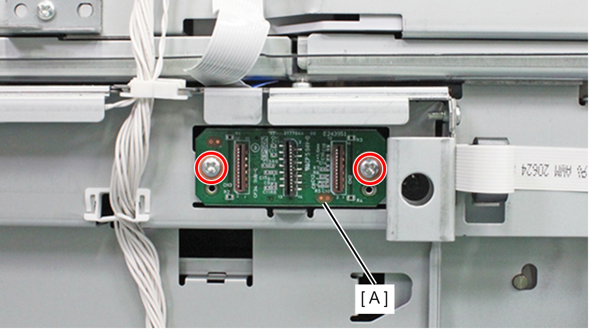
- : C.B.S-TITE-SCREW-3x8-F.ZN-3C